First presented at GPD 2019
Previously build - only based on general experience, now often sophisticated structural analysis is necessary to design a façade – but the structural design is often forgotten due to a lack of knowledge (structural and architectural design). At present we see damages to old facades but also to new constructions. These problems are increasing, up to collapsing façade elements.
This concerns of course also high rising buildings. First typically problems with facades are presented (due to analysis, regulations, design and execution). Aspects of inspection of hidden parts (brackets or gluing on the back) becomes more and more important. A code for monitoring is presented. The monitoring of glass-facades is investigated in an actual research work, first results are presented.
1 Introduction
There are a large number of facade variants with regard to material, design and fastening. Aluminium, Glass, plastics are used in everincreasing sizes of the elements. Single facades, double skin facades, element-facades are common meanwhile. Different kind of fixing – linear, in points, glued with special silicone or hidden on the back of the element – are used.
Glass as a transparent building material allows natural lighting of rooms. This means less costs for lighting energy as well as positive effects to people. The actual façade constructions are getting more and more complex, which leads sometimes to problems during the lifetime of the building. The aspects of monitoring (defects from the beginning or later occurring defects) and subsequent renovation will become more important in the future.
2 Regulations for Inspection
After a significant number of tragic building collapses in Europe at the start of 2006, a new guideline has been introduced in Germany. With the guideline VDI 6200, Structural safety of buildings – Regular inspections, a guideline for inspections of buildings was introduced.
The guideline VDI 6200 contains assessment and evaluation criteria and practical instructions for the regular inspection of the structural safety as well as recommendations for the maintenance of buildings of all kinds, with the exception of traffic structures. Building constructions are classified according to the possible consequences in the event of global or partial failure and their structural design.
However, only few know, that the guideline VDI 6200 must be applied also for facades. According guideline VDI 6200, facades are classified in consequences class CC2, same class as e.g. high-rise buildings or public buildings. CC2 means medium consequences: Damage to life and health for many persons and serious environmental damage. Furthermore, robustness classes RC1 – RC4 are described in the guideline. The Consequence classes are basis of Eurocode 1.

Depending on the Consequences class, intervals for periodic inspections are given as orientation values, se Table 1. This means that every 2 to 3 years it is recommended to do a surveillance by the owner or authorized representative for obvious defects or damages and the documentation thereof. Every 4 to 5 years an inspection by an expert shall be made and every 12 to 15 years a thorough examination by a special expert.
This includes parts of the structure, which are difficult to access. It may be necessary to take material samples to determine the remaining strengths and rigidities. Furthermore, any found defects or damages must be assessed in terms of their relevance for the structural safety of the building. Looking to common façade constructions, especially the point “examination of parts of the structure, which are difficult to access” causes problems. E.g. the examination of the fixing points of an element façade means often the complete dismantling of the façade.
Intervals for periodic inspections according guideline VDI 6200
3 Often faults and actual methods of examination and monitoring
3.1. Glass
In case of Glass facades, it is more or less simple to check glass-thickness with special measurement equipment.
In cases, where the mandatory “stamp” on the glass (with type of glass) cannot be found, it is also possible to check the type of glass (float glass / fully tempered glass / heat strengthened glass) during inspection with a special measurement equipment with the help of the so-called “Scattered Light Polariscope”.
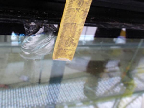
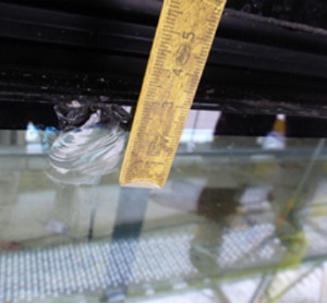
It is very hard to determine hidden damages in gluing ore hidden problems in the constraint areas, e.g. In the area of point fixings. Shelling defects are often hidden behind the clamping profiles (Figure 1). A partially dismantling often is necessary.
3.2. Structural Analysis
A widespread problem is a missing or incorrect structural analysis of glass and façade system. As for all structural components of a building, also for a façade, a structural analysis is necessary.
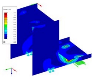
This may be often very complex and sophisticated. E.g. the Finite-Element analysis of the glass pane must cover all areas with stress peaks, e.g. the area of the bore in point-fixed glass panes. Facade-elements keep getting bigger and bigger and more and more transparent and filigree, the filigree mounting constructions are often on the “borderline”. In many events of damage of a facade, mistakes in the structural analysis are one of several reasons.
3.3. Screws
Drilling screws and self-tapping screws are great products to fix façade-elements. But ere also a structural design is necessary.
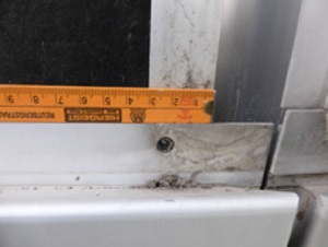
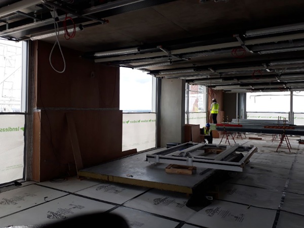
The most times hidden screws are sometimes forgotten (Figure 3), of the wrong type, with to small distance to the edges and do not fulfil the principle of “anchor point” and “expansion point”.
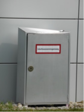
An examination means often the dismantling of the elements. Figure 4 shows the damaged box for fire-fighting water after impact of a façade element fixed with wrong screws.
3.4. Glass support
For the glass support rules concerning arrangement and design are existing. Here e.g. the size of the glass support and the distance from the edges are given. The glass support has to support minimum the whole thickness of the glass pane. Reality, unfortunately, shows the situation quite different (Figure 5).
3.5. Longitudinal expansion
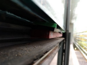
The thermal length expansion of a façade has to be considered in design. One solution is to design the connection to the substructure with fix-points and moving points. In actual practice the moving points often do not exist, are seized or flush with the end-stop.
3.6. Leakage
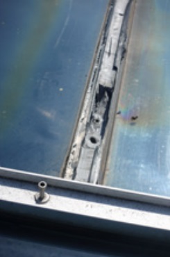
A major problem is leaking facades, especially in the areas of attics or flat sloping roofs. Here it is often the case that the channels under the cover strips are filled with silicone (Figure 6), which is counterproductive. The moisture cannot run off or dry off, with the result that standing water shreds the edge seal, penetrates into the cavity between the panes or even into the rooms below.
3.7. Impact
In case of an anti-drop device, beside the structural analysis of glass the proof of impact is necessary. Usually the glass thickness is specified according tables with experience values or by calculation. A third method is testing in laboratory or direct on the building site.
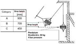
The standard testing method is the so called pendelum impact test, see Figure 7.
It is of course possible to do the test with an existing construction during inspection – with the risk of glass breakage.
4 Research project: Development of a Mobile Device for the Evaluation of the Current in Situ Stress Condition in Glass
Together with TU Ilmenau, RWTH Aachen and Verrotec GmbH Mainz, the consulting engineers office of the author is working at present on a research project. This project is funded by the German Federal Ministry of Economics and Energy (ZF4075115AG6) within the framework of the Central Innovation Program “Mittelstand” (ZIM) and deals with the development of a mobile device for the the evaluation of the current in situ stress condition in glass. Mechanically fixed and glued constructions will be determined.
A concept and functional model for the application of a mobile device for measuring qualitative flat stresses in glass components based on photoelasticity including application software is to be developed. (Schaaf 2018).
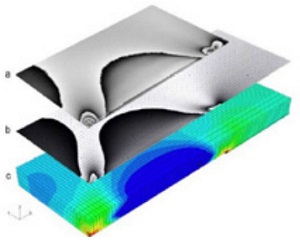
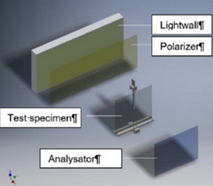
Photoelasticity is based on the visualization of the birefringence of optically isotropic or polarized light in transparent materials like glass with the aid of a circular polariscope. Unloaded glass is not birefringent, but loaded glass shows the property of birefringence due to the stress state in the glass.
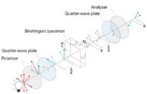
The polarized load vector splits into two perpendicular components when passing the loaded glass element (Figure 8). The directions of this vectors are the same of the principle stresses σ1 and σ2. The so called “main equation of photoelasticity” is shown in eqn (1) (Schaaf 2018, Hildebrand 2010)

C: photoelastic constant, σ1 and σ2: principle stress, λ: wavelength, δ: phase shift, D: thickness
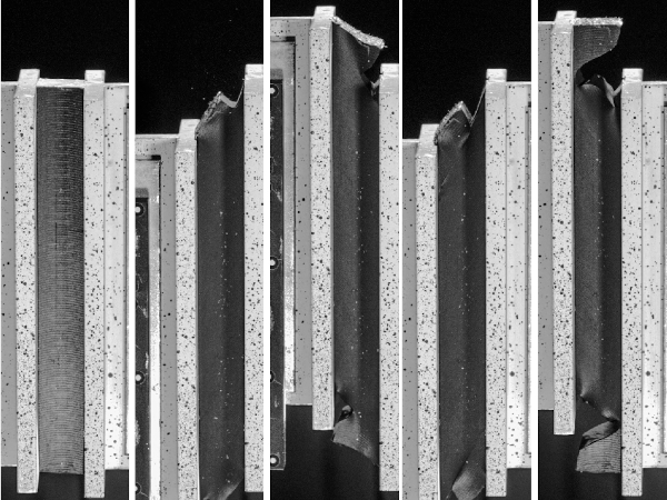
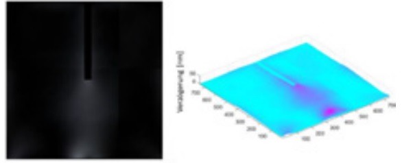
In the Context of the research project, several experimental setups are being investigated. One of them with a bonding is shown in Figure 10. Within the scope of the investigations, both homogeneous bonds and faulty bonds were examined.
The glass is loaded with 2000N, the higher the load, the brighter the areas around the adhesive (Figure 11).
With the method of stress optics, the state of stress in the glass of bonded joints can be examined. Further investigations will follow.
5 Refurbishment of facades
Refurbishment of facades is often caused by energetic aspects (in former times more or less monolithic layers, now triple IGU’s) or architectural aspects (design). To safeguard the well-being of the user and providing a worst CO2-balance by providing any cooling or air conditioning systems, nowadays double skin facades are often a main point of refurbishment, especially for high rise buildings.
Meanwhile there are a number of variations of types. The main characteristic of a double skin façade are two layers: The outer layer has the function as weather protection. The outer layer is not openable and in most times made of monolithic glass.
The inner layer has the function as insulation element, so the glass type is most times insulation glass. The gap between inner and outer layer is often ventilated, there are little openings in the outer façade to reach sufficient ventilation.
Often it is possible to open the inner layer, so it is possible for the user to regulate the climatic surroundings inside the building individually. In the gap between the layers an outside sun protection can be installed which is protected against weather and wind influence.
The strengthening of a facade may be necessary caused by:
• Problems with the ultimate limit state caused by mistakes in design
• Mistakes in execution
• Problems with ultimate limit state caused by energetic renovation with thicker, heavier IGU’s
Problem solvers are:
• Strengthening of metal construction
• Using of special glass products (e.g. stiff interlayers) to reduce the weight of glass
• Complete new façade according actual state of art
6 Conclusions
The actual façade constructions are getting more and more complex. Beside a proper structural design, the inspection and monitoring of the structural safety of the façade after several years is very important. New measurement methods based on photoelasticity may help to find hidden problems.
Refurbishment of facades may be necessary due to damage to the façade or architectural or energetic upgrading. This means sophisticated construction in existing building.
References
(1) VDI Richtlinie 6200, Structural safety of buildings – Regular inspections, 2010.
(2) Siebert B., Maniatis I. A new Façade Concept for an Existing Office building. Challenging Glass 2 Delft 2010.
(3) Siebert B. Modern Facades made of Glass. IABSE Chicago 2008.
(4) Siebert B. Modern Facades of tall building. GPD Tampere 2009.
(5) Siebert B. Refurbishment of facades. GlassCon Global 2018 Chicago
(6) DIN 18008-1: 2010-12: Glas im Bauwesen – Bemessungs- und Konstruktionsregeln – Teil 1: Begriffe und allgemeine Grundlagen.
(7) DIN 18008-2: 2010-12: Glas im Bauwesen – Bemessungs- und Konstruktionsregeln – Teil 2: Linienförmig gelagerte Verglasungen.
(8) DIN 18008-2: 2011-04: Glas im Bauwesen - Bemessungs- und Konstruktionsregeln - Teil 2: Linienförmig gelagerte Verglasungen, Berichtigung zu DIN 18008-2: 2010-12.
(9) DIN 18008-3: 2013-07:Glas im Bauwesen – Bemessungs- und Konstruktionsregeln – Teil 3: Punktförmig gelagerte Verglasungen.
(10) DIN 18008-4: 2013-07:Glas im Bauwesen – Bemessungs- und Konstruktionsregeln – Teil 4: Zusatzanforderungen an absturzsichernde Verglasungen.
(11) DIN 18008-5: 2013-07:Glas im Bauwesen – Bemessungs- und Konstruktionsregeln – Teil 5: Zusatzanforderungen an begehbare Verglasungen.
(12) SIEBERT B., HERRMANN T., „Energetische Sanierung Hypo Hochhaus – Gebogene 3-fach Isolierverglasung der neuen Doppelfassade“ , Glasbau 2014, Ernst und Sohn Verlag Berlin, 2014.
(13) Schaaf, B., Abeln, B., Richter, C., Feldmann, M., Glaser, M., Hildebrand, J., Bergmann, J.-P. Development of a Mobile Device for the Evaluation of the Current in Situ Stress Condition in Glass. Challenging Glass Delft, Netherland 2018.
(14) Deuschle, H.M., Wittel, F.K., Kröplin, B.-H.: Simulation von Spannungsoptik im Rahmen der FEM, 17. Deutschsprachige ABAQUS Benutzerkonferenz, Nürnberg (2005)
(15) Schaaf, B., Di Biase, P.,Feldmann, M., Schuler, C., Dix, S. Full-surface and non-destructive quality control and evaluation by using photoelastic methods, Glass Performance Days 2017, Proceedings, Tampere, Finland, (2017)


