Source: Glass Structures & Engineering
Authors: Maximilian Laurs & Markus Feldmann
DOI: https://doi.org/10.1007/s40940-024-00289-6
Abstract
Traditionally, curved façade geometries can be achieved by the means of hot bending glass or tessellation of the underlying geometry into plane parts, or even combinations of aforementioned. While the first method is not cost, nor energy efficient, for it relies on a heating process and requires bending moulds for every geometry, the second requires a vast amount of opaque substructure, opposing the aim of translucent façade structures. Contrary to these methods, the cold bending of glass omits those detrimental side effects of modern façade design. So, a promising technique was developed by elastically applying the curvature at ambient temperature. Nevertheless, the widespread use is still opposed by surmounted imponderables, like advanced calculation models utilizing FEAs and missing experience in the application of this method. This paper gives an extensive overview of the state of the art, like realized structures, deformation criteria and cold bending associated stress development, while also prompting a new analytical approach for the calculation of stresses in cold bent glasses. Moreover, a time-dependent buckling phenomenon on laminated glasses is discussed. In conclusion, aspects of the upcoming informative annex of the prEN 19100 (Eurocode 10 to be) on cold bending are discussed.
1 Introduction to cold bending of glass
The practice of the bending of glass components into their desired shape without the use of thermal processes (re-softening of glass during bending by own weight or force) has now been used and further investigated for more than twenty years. During this period, the cold bending of glass has been used in a multitude of façade or roof projects, each with their own varying demand on the geometry and therefore the cold bending method itself and the glass component.
The process family of general cold bending can therein be differentiated into two genera, namely lamination bending and permanent cold bending. The former is characterised by the fact that the initially elastically applied deformation is maintained by a subsequently produced shear bond between two or more glass panes. Because of the time-dependent stiffness of the shear interlayer, this procedure is connected to a so-called spring-back effect. Therefore, the façade substructure needs to accommodate for the geometry of the glass pane, with creep and relaxation effects being accounted for. This effect was the subject of extensive studies in Galuppi and Royer-Carfagni (2015). The time dependent behaviour of the glass pane is herein only of importance during the production stage, but not during the built-in state.
This is the decisive difference to the latter process, the permanent cold bending, which is the main subject of this article, wherein time-dependent features of this procedure are highlighted for the first time. It is characterized in such that the glass is bent in a given substructure and time-dependent behaviour can result in changes of deformation, stress state and resulting forces on the substructure. The method can be categorized by the following characteristics:
- Curvature of aspired geometrysingle curved vs. double curved
- Application of geometrybent into frame vs. bent with frame
- Glass componentsmonolithic vs. laminated vs. IGU
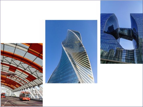
From single curved laminated glasses in roofs (Vakar 2012, Fildhuth 2014) without requirements on thermal performance, over single curved IGUs in facades (Eekhout 2010), also fulfilling energy efficiency requirements, the requirements for cold-bent elements have steadily increased over time. Subsequently, more complex geometries with curvatures in more than one direction were developed. Prominent examples are the Turning Torso in Malmö (Voller 2004) or the Evolution Tower in Moscow (Nikandrov 2016), see Fig. 1. Both utilised the hypar form realized by a glass pane, which has one corner of its initial flat geometry moved out of the plane containing the remaining three corners. The most recent and prominent example might be the Opus in Dubai, facilitating both, hot and cold bending techniques, in his complex façade geometry (Koltay 2016). In the case of the most complex facades, the mechanical design of cold bent glass structures also has to go hand in hand with considerations of panelization, developability and optimization, as shown in Gavriil (2020).
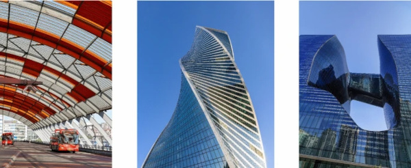
The work of Gavrill also marks one of the latest findings of extensive research activity conducted parallel to the built examples. Starting from Staaks (2003), van Heerwijnen et al. (2004) and Vakar & Gaal (2004), who investigated point supported glass panels and, for the first time, discovered a deformation induced stability issue of the regularity of the panes’ geometry development, which they then approximated with a lattice model. Over Datsiou (2017) and Galuppi et al. (2018), extending these findings on numerical investigations, including linearly supported geometries. Outstanding research has therein been done by Galuppi et al. (2014) stating, that the linear Kirchhoff–Love plate theory (Kirchhoff (1850)) is not sufficient to describe the observed behaviour, but a formulation of higher order needs to be applied—choosing the second order von-Karman plate theory. In order to calculate stresses and deformations therein, the prescribed deformation figure needs to adequately reflect the in-situ deformations.
Galuppi chose the formulation of a hypar (w = cxy), whereby the straightness of the edges is implicitly required. This approach proved unfeasible for deformations of higher magnitude. Nevertheless, an analogous model, comprised of the superposition of two cylinders being bent into the desired hypar shape, which was able to predict the required bending forces sufficiently, but could not predict the buckling point, was developed. This approach was then picked up by Nehring (2019) who proposed in his dissertation the use of this function, or its derivations respectively, to calculate the membrane stresses in the glass pane. His analytical explanations then concluded, that a formulation of higher order was inevitable to realise the numerically calculated stress distributions. Despite a violation of the geometric boundary conditions, it was then still possible to achieve good agreement of numerical and analytical stress distributions. Nevertheless, a derivation of the buckling point via a variation of the systems potential was not possible, but experimental determinations of the buckling point were provided.
Today, the most recent research focuses on the transfer of the above-mentioned insights onto the typical glass components, with laminated glass and insulating glazing units (IGUs), or combinations thereof, being the most prominent ones. To be mentioned are the works of Muja et al. (2021)—numerical approach—and Santi & Royer-Carfagni (2024)—analytical approach—on single curved laminated glass. Where Santi uses fractional approaches and a description of the interlayer time-dependent viscoelastic behaviour via power laws, while validating their analytical approach on a numerical model enabling Prony-series, in order to consider the time-dependent material behaviour. IGUs were thoroughly investigated by Beer (2015) and Pölzl (2016), both emphasizing the stresses occurring in the edge seal following the bending process. Thereby focussing on the load capacity of the edge seal, but struggling with singularities in the vicinity of the panes’ corners. Therefore, already then, hand calculation methods have been promoted. Sitte et al. (2021) provided such method, for small deflections of structural edge seals.
Moreover, this component of the IGU shows strong time-dependent behaviour as well and its structural integrity is crucial to the IGUs performance over its lifetime. This has already been acknowledged by edge seal producers, e.g. Sika AG (2024) giving simplified advice on the use of IGUs in cold bent glass applications. The coupling of the glass panes via the edge seal also has to be considered during calculation. As known from the usual calculation of IGUs, the stiffness of each comprising glass pane decides the load sharing of the two panes. A change of the cavity volume due to the deformation and a resulting gas pressure change could also be possible and needs to be addressed, see Zhang et al. (2021), van Driel et al. (2022) and Demontis et al. (2022), Scherer et al. (2021) . Since it has been shown that the buckling behaviour of cold bent glass depends on the thickness, the contemplations of laminated glass and IGUs have been woven together. For the effective thickness of a laminated glass depends on the viscoelastic behaviour of the interlayer, and is therefore time-dependent as well, the load distribution of a laminated IGU under external loading and the utilisation of the edge seal becomes also time-dependent.
Summarising, in order to maximize the potential use of cold bent structures, these various mentioned issues need to be addressed. This article illustrates these subjects using experimental and numerical investigations and closes with a proposal for further analytical investigations, as well as an overview of the most recent normative developments regarding the cold bending of glass.
2 Different effects on cold bent glass structures
Cold bent glass components underly a multitude of different effects, resulting from both external loads (like wind, snow, temperature) and inherent loads (bending process itself, change of systems’ stiffness). These effects and their corresponding affects are furthermore influenced by time- and temperature-dependent parameters. These have a direct influence on system characteristics that are crucial to an efficient and durable design of said components. Components are herein defined as the assembly of monolithic or laminated glass products alone, or in combination with spacers and edge seals in IGUs. The effects of the loading on the substructure are omitted.
The most prominent effects result from the bending process itself. This state is achieved by means of imposing an elastic deformation via a movable frame structure with articulated joints, retaining the glass component in a preinstalled frame structure or bend both, the frame and the frame structure. In the beginning, in order to understand the underlying mechanisms, the bending behaviour of monolithic glass panes was investigated. Starting from a master’s thesis by Staaks (2003), with a focus on point supported panes, more and more insights on cold bending were accumulated over the last years.
The process of cold bending a point supported glass pane is shown in Fig. 2. It also shows the relevant deformation states and coordinate systems referred to in this article. It is important to recognise that the different loading conditions (one corner displaced by dZ, two opposing corners displaced by dZ/2 each and two opposing corners displaced by dZ/4 and the remaining displaced by −dZ/4) are equivalent. They can be transformed into each other via appropriate coordination transformation. Therein it is crucial, if the reaction forces at the boundary conditions allow force components in the plane of the glass. If in-plane forces are introduced into the pane, the buckling behaviour is significantly distorted. Apart from statically determined boundary conditions in the initial position, the pane should be free of possible constraining forces.

During cold bending, with regard to the stresses, bending as well as shear and membrane stresses are introduced into the initially flat and stress-free component. This leads to a complex superposition of all those stresses, whose proportionality strongly depends on the degree of cold bending. For small curvatures of the geometry (alternatively small deflections of one or two corners, or small deflection angles of the edges, which can all be used equivalently and be converted into each other) the main stress component remains the in-plane shear stress τxy. With rising deflection, the share of bending stresses σbend grows, exceeding the shear stresses. For a square plate this is exemplarily shown in Fig. 3. The abscissa is therein normalized by the panel thickness, for Staaks (2003) derived a linear influence of the pane thickness on the critical corner deflection dZcrit.
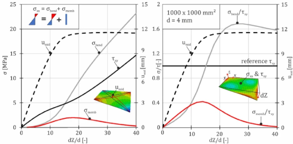
On the left side, the absolute development of the shear stress τxy and the cross-sectional stress σxx in the middle of the plate, which is equal to σyy, and its components, as well as the mid-deflection umid are shown. It is seen, that especially for deflection with dZ<d, the most prominent stress is the shear stress. For higher deformations, this does not hold true. At dZ/d≈15 the bending stresses σbend surpass the shear stresses. At this point, the rate of the deflection change starts to slow down, which is shown in an inflection point in the derivation of the umid-graph. This inflection point marks the moment of buckling.
The developed membrane stresses σmemb reach their maximum a little bit later, but the maximum of the ratio of membrane stresses to shear stresses σmemb/τxy coincides with the onset of buckling. This is shown on the right side of Fig. 3. It is also shown that the ratio of bending stresses σbend/τxy reaches a maximum for the highest investigated orders of deflection (dZ/d>25) and the membrane stresses become negligible in this domain.
2.1 Numerical investigations
In order to characterize cold bent glass applications, it proved vital to have a distinct knowledge of the achievable deformation states, for these highly influence not only the visual appearance and therefore quality of the facade, but also the load bearing behaviour, stress distribution and effects on components of the glass assembly. In Feldmann & Laurs (2024) it was shown that the direction of the initial imperfection of a glass pane relative to the corner deflection influences the achieved buckling mode and the starting point of the buckling phenomenon. Continuing, due to the dependence of the buckling behaviour on the glass thickness, the influence of a time-dependent effective thickness of the laminated glass pane and its influence on the buckling behaviour was studied. This was already done for intentionally in plane loaded beam-like glass components in Galuppi & Carfaghni (2014) or Langosch & Feldmann (2012), where the time-dependent buckling resistance of laminated glass components was studied. Therein, the authors found that different critical buckling loads exist depending on the time-variable effective thickness of in-plane loaded laminated glass elements.
Contrary to these earlier studies, the presented calculations of cold bent glasses exhibit no explicit in-plane loading due to external normal forces. The stability phenomenon is provoked due to membrane stresses resulting from high levels of out-of-plane deformation. Because the magnitude of those stresses depends on the thickness of the glass pane for monolithic glasses, it is close at hand that laminated glasses with a time-dependent effective stiffness show a time-dependent change in their buckling resistance as well.
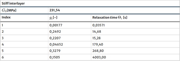
In order to quantify this influence of the time-dependent shear coupling of two glass panes, viscoelastic calculations have been conducted with the FEA program ABAQUS. While the modelling of the cold bending behaviour itself stayed the same as in Feldmann & Laurs (2024)—geometrically non-linear calculation of glass panes with Young’s modulus of E=70.000MPa and Poisson’s ratio of ν=0.23 composed of C3D20R elements – the time-dependent behaviour of the interlayer was additionally modelled on the basis of manufacturer’s information coming from Kuraray (2024). Table 1 was derived from the times, Young’s moduli and shear moduli given in the manufactures data, via a fitting of a Prony series to the given function. The Prony series had the general form shown in Formula 1 and consisted of six Prony elements:

where g(t) is the time dependent factor for the instantaneous shear modulus G0, Θi are the relaxation times, and gi the fitted time-dependent moduli in dimensionless form (divided by the instantaneous modulus) (ABAQUS 2024).
Table 1 Prony parameters derived from manufacturer’s data and used for described investigations - Full size table
These values were found to give good fits to experimental data of cold bent laminated glass plates. Following these experiments, the effect on a larger timescale was investigated numerically.
In the calculations, the pane is bent into its desired shape in a full viscoelastic calculation over a time period of 600s. This was achieved by using a “General—Visco” step in ABAQUS, which is used to calculate a transient response in an analysis with time-dependent material behaviour, accounting for the load history and the damping of the underlying generalized Maxwell model of the Prony series. After the bending process a second transient step is calculated, where the deformation of the supported corners of the plate remains unchanged and the stresses and deformations are calculated over the time period of a month. This is done, because of the time-dependent stiffness of the glass plate. For it is known that thicker plates buckle at higher corner deflections, the decay of the effective thickness over time can become significant.
The findings of the numerical calculations are illustrated for a symmetric point supported laminated glass pane. Figure 4 shows the well-known buckling phenomenon, already described in e.g. Galuppi et al. (2014), but for a laminated glass pane and its onset due to time-dependency of the interlayer’s stiffness. In this example, a square plate (1mx1m) of two 4mm glass plates, joined by a 1.52mm interlayer was bent, by moving two opposing corners 40mm each out of their initial plane.
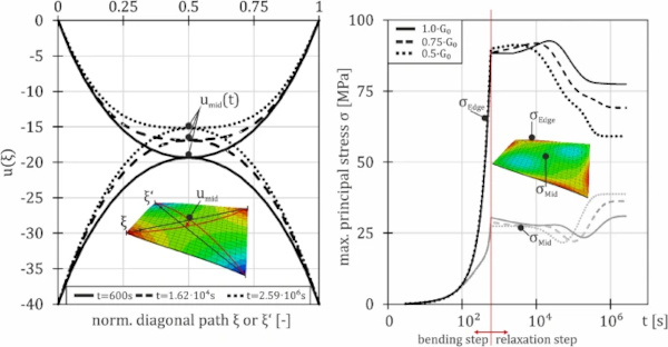
On the left side of Fig. 4, the deformation of the diagonals is shown over their normalized length ξ. One can see, that for the state at t=600s, both diagonal deformations are qualitatively the same. This indicates that the plate has not buckled yet. The deformations of two discrete later timepoints are also shown. It is seen, that the mid-deflection of the plate changes, what leads to a broadening of the graph of one diagonal, while the other one is narrowed—the plate has buckled.
This effect results from the decay of the effective stiffness over time. During the short time of bending, the effective plate thickness might be close to a perfect shear coupling, which would correspond to an effective thickness of roughly dini=8mm which leads, for a deflection of dZ=80mm, to no buckling phenomenon. Then, during the second step the effective thickness, deff(t) becomes smaller, finally surpassing a value that corresponds to a dZcrit smaller than dZ=80mm and therefore leading to a delayed buckling phenomenon.
This also effects the stresses of the plate. On the right side of Fig. 4 the maximum principal stresses of the upper side are shown for two discrete spots, the midpoint of the plate and a point on an edge close to a corner, respectively. The stresses at the middle point σMid are significantly lower, than the stresses at the edge σEdge. Obviously, it is seen that the stresses decay corresponding to the plate’s stiffness decay, as it is to be expected in a deformation-controlled test setup, like the cold bending application.
The graph also displays the influence of different initial interlayer stiffnesses. Via the variation of the initial shear Modulus G0 (the elastic shear modulus) with the factors 1.0, 0.75 and 0.5, the decaying behaviour – respectively the relaxation times, or the viscous properties – of the Prony series was not influenced, but the resulting plate stiffness itself.
As expected, for stiffer interlayers the stress magnitudes are higher. But surprisingly, the stress maximum at these points is reached after the bending process itself (after approx. tmax=104s). This results from the change of the deformation figure into the buckled shape. At the beginning of the relaxation, the pane has not buckled yet. Both diagonal deformations are equivalent. Up to times of around t=10⁴s the increase of stresses due to the change into the buckled mode outweighs the stress reduction resulting from the relaxation in the interlayer. Afterwards the stress decays and settles at a lower level. The difference of the midpoint stresses and the edge stresses is more significant for the stiffer interlayers.
2.2 Semi-analytical approach
For the calculation of cold bent glasses in the investigated deformation states the linear plate theory according to Kirchhoff (1850) loses its validity. Because this formulation of the force equilibrium neglects the rise of membrane stresses it is only valid for small deflection magnitudes in the range of the plates’ thickness. For thin plates under moderate deformations the von-Karman equations can be applied. These couple the deformation of the plate according to Kirchhoff w(x,y) with an Airy stress function of the in-plane stresses ϕ(x,y). The result is the following formulation:

where

And also

This can also be described to define the 2-dimensional Laplace-operator Δ as:

And the plate stiffness D as

while in the special case of the process of cold bending the external normal force per unit area r equals zero.
To solve this equation, a suitable deformation function is to be chosen. After a validation process of a numerical model on experimental data, the following function composed of a set of transcendental functions was chosen.

The parameters a,b,p and q of this function are to be chosen according to the boundary conditions of the system. w0 is a scaling parameter, representing the magnitude of the corner deflection.
One key feature of this formulation is that the boundary condition of straight edges is no longer inherently prescribed, contrary to approaches used in the younger literature. Especially, for point support glasses this proved to be vital for the exact calculation of stress distributions.
After differentiation of Formula (7) and insertion into Formula (4) one obtains an expression for the double Laplace derivative of ϕ as a sum of transcendental functions. For the individual parts of the sum one can find so-called harmonic functions, which are by definition twice continuously differentiable functions. With the help of these, one can raise the level of ΔΔϕ to ϕ. A simple example of one step, where C is a constant that needs to be evaluated later, is given below. The procedure of linear composition of basic transcendental functions has to be exercised for

By deriving ϕ twice from x, one obtains the function for σyy in the mid-plane of the pane. Respectively, σxx is obtained by deriving ϕ twice from y, and τxy from two derivations of ϕ, once from x and once from y.
The factors a,b,p and q can then be determined via the respective boundary conditions of the problem at hand. They can also be fitted onto the result of a numerical experiment, to validate the assumed deformation function. This was done via a Python program utilizing the function “scipy.optimize.curve_fit()”. This function takes the function from Eq. (6) fitting it to a given set of data, in this case the numerical results on every node in the mid-plane of the glass pane, and minimizes the error using a non-linear least squares algorithm, starting from an initial guess. The minimization of the error is performed by the use of a so-called Levenberg–Marquardt algorithm (see ScyPy (2024)).
The result of the optimization can be seen in Fig. 5. The complete normalized deformation figure of plate with aspect ratio a×b=1000×1000mm² and a thickness of d=4mm and a corner deflection of dZ=40mm is shown on the right side. On the left side the discrete fit of the function along the diagonal and along one edge (for x=1,0) is shown.
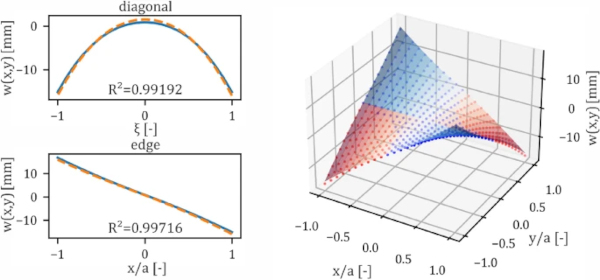
To check the goodness-of-fit of the optimized model, the deformation of the analytical model along significant paths is compared to the numerical model. Therefore, the coefficient of determination R² is used, providing a measure of how well the numerical outcomes are replicated by the analytical model. It is calculated with the following formula.

where wi(x,y) is the discrete deformation value at the point i with the coordinates xi and yi from the numerical calculation and wfit,i(xi,yi) is the deformation at the point i calculated with the fitted model. Moreover, w¯ is the arithmetic mean of the deformation values of the numerical model along the investigated paths. The investigated paths are:
- Along the diagonals (w(x=y) and w(x=−y))
- Along the free edges (w(a/2;y) and w(x;a/2))
The quality of the fit is found to be very good, which leads to R2∼1 (see Fig. 5).
The development of the parameters a,b,p and q has been subject to the ongoing research. The deformation constraint at the corners of a normalized element with half-edge length of 1 leads to a simplification of the formula, revealing an expression of a in dependency of q. Therefore,
![]()
yields,

The factor p has been found to be in close proximity off π and was chosen this way in an attempt to narrow down the possible optimization results. With 2 parameters left (q&b) a relation of the parameters to the corner displacement could be found. Figure 6 shows the result of the carried-out optimizations. Every marker therein stands for a deformation state to which the derived formula was fitted, all with coefficients of determination close to 1 for the mentioned paths.
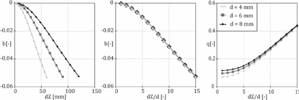
It can be seen, that the magnitude of parameter b rises with higher cold bending amplitude. Following a non-linear behaviour, it could be linearized after deformation magnitudes larger than 5-times the plates thickness. In the middle of Fig. 6 it becomes obvious, that this hold true for all three investigated thicknesses. Also, the parameter q seems to follow a linear behaviour from approximately the same deformation magnitudes than the parameter b. Nevertheless, here, a thickness influence is obvious that could not be sufficiently explained yet.
The liability limit of the semi-analytical function is still the buckling limit dZcrit. This would be reached at dZ/d=16.3 following Staaks (2003). After the onset of buckling, the geometry loses one symmetry plane and evolves in a way the presented formula cannot describe sufficiently.
Nevertheless, the formula will be helpful, when trying to determine the exact buckling point with energy methods. Moreover, it should be applicable for laminated glasses, considering an adequate effective thickness.
These findings will be checked against further variation of the thickness and aspect ratio in the future.
2.3 Normative approach
The extensive research on the cold bending of glass has already led to a recognition of CEN committees. During the preparation of the upcoming Eurocode 10 “EN 19100—Design of Structural Glass” the committee CEN/TC 250/SC 11 decided to incorporate an informative annex on this subject. While not giving explicit calculation rules for cold bending, this annex represents the innovative character of normative work. In giving an “alert-list-like” overview of subjects to be considered when using cold bent glass, the annex will foster the acceptance of such technique and will therein promote the ongoing research and ultimately the use of this method.
To give an overview of the annex’s topics, Fig. 7 summarizes the considered technical aspects. The scope of the annex only mentions elastically cold bent glass. A transfer on laminated glasses, where the bending is achieved with the lamination process, could therefore be possible. One can easily recognize the typical structure of a Eurocode document. The annex is organized according to the main Limit States of the Eurocode suite, namely “Ultimate Limit State” (ULS) and “Serviceability Limit State” (SLS). Moreover, the newly introduced Limit States of prEN 19100 “Fracture Limit State” (FLS) and “Post-Fracture Limit State” (PFLS) are considered.
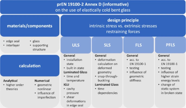
This accounts for the influence of the elastic stresses in cold bent applications, that have an effect on the fracture pattern of glasses. As Pourmoghaddam et al. (2019) addressed in his thesis, the fracture pattern of glass depends on the strain energy present during the breakage. Primarily observed on thermally tempered glasses with varying degrees of pre-stress, this phenomenon was also observed on cold bent glasses by Driel et al. (2022) or Laurs et al. (2020), where the high strain energy values result from the cold bending process and lead to influenced fracture patterns. The failure of single plies in combination with this phenomenon can influence the post-breakage stiffness remarkably and lead to time dependent stress peaks, that should be considered in early design stages. The tests to verify the breakage and post-breakage behaviour of cold bent glass should comply to the tests referred to in prEN 19100 in the end. Finally, guidance on feasible calculation methods is given and points of interest, as the stress on the edge seals of IGUs, are highlighted.
Nevertheless, since the annex is only informative, the member countries will not be obliged to introduce the annex in their respective national publication of the Eurocode 10. The annex could still be altered, or even left out completely.
Finally, it is to be noted, and to be promoted, that the current state of the Eurocode 10 is the state of a pre-standard. It will therefore be sent to Enquiry by September of 2024, to give the European CEN member countries again the opportunity to comment on the latest version. After the collation and incorporation of the comments, the standard will then be voted on and in case of positive outcome be published as a full-fledged Eurocode by 2027.
3 Summary and outlook
Conclusively, it can be subsumed that the research on cold bent glass is still vibrant and the development of a sustainable way to achieve complex façade geometries is still ongoing.
A deeper understanding of the mechanisms responsible for the behaviour of the glass plate during the cold bending process was mediated by showing the different stress contribution over the process’s duration.
For laminated glasses it was shown that the final deformed state of the cold bent glass depends on the viscoelastic properties of the interlayer. Depending on its stiffness, a delayed buckling effect might be observed. The connotated stress distribution might lead to unsafe assessments, when only the limit states (full shear coupling or no shear coupling) are assessed. The shown research on laminated glasses highlights a problem that is rarely discussed, but should be part of every cold bending design process.
Finally, a new analytical approach for the deformation figure of point supported glasses was proposed and evaluated. It was found to have good agreement with numerical models that were validated on experimental results in earlier research.
The upcoming work will be to evaluate the stresses of the newly proposed deformation function and then pinpoint the free values concretely to boundary conditions.








Comments
The paper effectively addresses these challenges by providing a comprehensive overview of the current state of the art, including existing applications, deformation criteria, and stress development in cold-bent glass. Furthermore, the introduction of a new analytical approach for stress calculation is a valuable contribution. The discussion of time-dependent buckling in laminated glass adds another layer of crucial understanding to the long-term behavior of these structures.
Watercooled Intel Core Series Servers