Article Information
- Digital Object Identifier (DOI): 10.47982/cgc.9. 610
- Published by Challenging Glass, on behalf of the author(s), at Stichting OpenAccess.
- Published as part of the peer-reviewed Challenging Glass Conference Proceedings, Volume 9, June 2024, 10.47982/cgc.9
- Editors: Christian Louter, Freek Bos & Jan Belis
- This work is licensed under a Creative Commons Attribution 4.0 International (CC BY 4.0) license.
- Copyright © 2024 with the author(s)
Authors:
- Peter Lenk - Arup
- Peter van de Rotten - Octatube
- Ed Forwood - Forwood Facades

Abstract
In this paper, we will discuss a challenging, iconic, heritage, refurbishment project – Channel 4’s headquarters building located in London, England. The building was originally designed by Richard Rogers and Partners in collaboration with Arup, RFR and was executed in 1994 by Eiffel under a sub-contract package with Permasteelisa. We will methodically outline the procedures that were followed to assess and restore this aging, iconic cable net façade where, in an almost unprecedented way, the face glass is used structurally to support the dead load of the panels below to create a chain of suspended glass panes. After approximately 25 years of service Arup was called back to provide advice to the client following a glass breakage incident. This triggered a detailed condition survey which concluded that a project refurbishment was overdue. Arup then provided further studies to inform strategic options as to how to best refurbish the façade. This advice led to the appointment of Octatube to provide Pre-Construction Services Agreement (PCSA) support to assist the façade appraisal and to carry out design, material testing, calculation and to provide critical construction advice, and then lead to Ocatatube’s appointment to fully refurbish the iconic façade.
1. Introduction
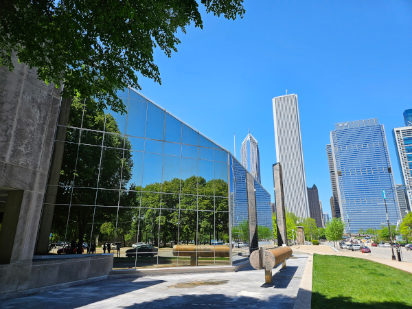
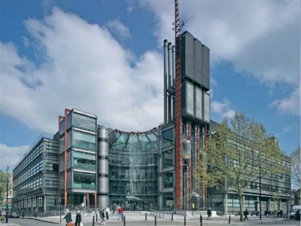
The Channel 4 headquarters building, an iconic, grade 2 listed and exemplar of the Hi-Tech movement, located in central London is now 30 years old. A key feature of this building is its entrance atrium with its pre-tensioned cable net structure and glazed façade which has recently undergone a major refurbishment. The refurbishment work was triggered by the discovery of significant wear and tear in some parts of the cable net and in the glazing and the glazing fixings. These discoveries led Arup to conclude that some key assumptions of the original design had been compromised and to conclude that a refurbishment cycle was necessary. To inform an initial project appraisal (with the help of the original specialist contractor’s designer Eiffage) an abseil survey was carried out (with support from Permasteelisa). This was followed by a more detailed geometric and drone-generated photographic record (with support from Texo) and a tension state survey of the cable net structure (with support from Base). The involvement of the specialist façade contractor Octatube was then introduced, early in the design phase to help assess the survey results and provide detailed advice on the technical and sequential complexities of the refurbishment. Octatube then continued to carry out more detailed design and finally delivered the necessary refurbishment.
The glass curtain to the front atrium of the Channel 4 headquarters building is bespoke, sophisticated, and unique. It was considered ground-breaking at the time of its design and construction in the early 1990s. The design approach set out to use the face glass as a chain or net of hung elements, an approach that was not widely adopted by subsequent projects which typically adopted additional dead load rods in lieu of using the glass itself as a tension load path. It is reminiscent of the “La Villete” project in Paris as documented in the seminal technical book Rice, P. Dutton, H. Structural Glass (1995), a book which also includes a short section on the Channel Four headquarters building itself.
This project was well documented in Arup’s and the client’s archive, as well as featured as a case study in other publications such as Addis, B. The Art of the Structural Engineer (1994) and as documented in the Richard Rogers and Partners publication Sudjic, D. Channel 4 Headquarters London (1996).
The Channel 4 headquarters building in London was designed by Richard Rogers and Partners and opened in 1994. The concept for the Structural glass façade was developed by Arup and the detail design was further developed by RFR and Eiffel. The subcontractor responsible for the manufacture and installation of the wider building façade package was the Permasteelisa group who in turn subcontracted Eiffel for the atrium façade and canopy.
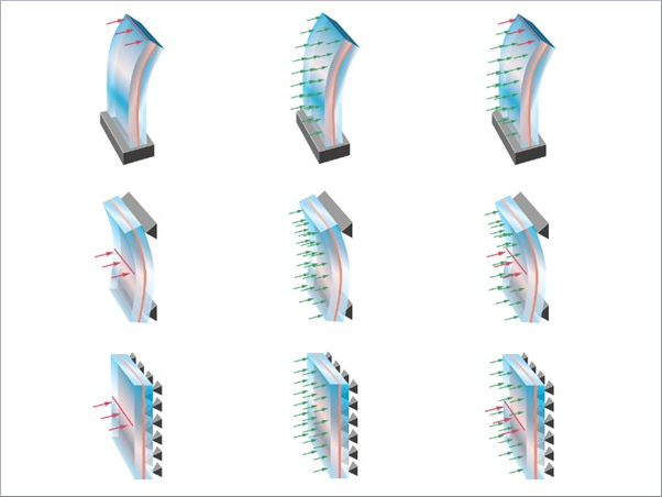
The main glazed entrance facade consists principally of an inclined glass roof and a vertical façade with flat and curved sections. In the original design the main vertical section used fully toughened curved glass panels. The majority of these are point-fixed and use monolithic glass. Laminated glass in the vertical section was only provided at ground level. The glass screen is suspended as a chain from an array of steel cantilever beams at roof level and typically laterally restrained by a two-way spanning pre-tensioned, tensile steel cable net.
The main section of the entrance screen is curved in a quarter circle with 12mm thick monolithic toughened glass above ground floor level and 2x8mm laminated glass panels at ground level. The glass build-up to the flat returns is similarly arranged. The roof panels were also laminated with a total thickness of 24mm.
The joints between glass panels were typically sealed with a low-modulus black silicone supplied by Dow Corning, which provided the weather tightness of the atrium. Exceptions to this were the vertical joints at the corners between the curved section of the screen and the adjacent straight sections. These corners are unsupported by the inner cable net, and here silicone is required to enable the glass itself and silicone to provide together a robust load path for any applied wind loading.
The glass curtain has several unique design features of which the most notable are:
- It uses monolithic toughened curved glass (structural glass walls constructed in recent years have more typically used laminated glass which provides greater post-breakage redundancy),
- The glass is suspended as a chain of glass panels with each panel being hung progressively from the panel above (structural glass walls constructed after this project typically included an independent dead load rod to carry the glass self-weight),
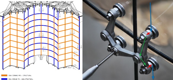
- The glass wall uses structural silicone in key locations as part of the structural load path, the silicone selection is tuned to the structural or non-structural function of panel-to-panel joints,
- The fixings used to suspend the glass were a new, innovative technology developed by RFR and tested specifically for this project,
- At the top of the wall a series of spring elements were designed to soften the vertical load path and ease, cushion or provide a smooth transition to any necessary load redistribution in the case of the breakage of any single unit. The intent was that any change in the required glass dead load path due to the breakage of any single unit would not be abrupt and thereby cause progressive failure.
During Arup’s initial review and during key industry buy-in interviews (not only with Octatube but also with other potential partners who were under consideration to provide Pre-construction services agreement) it became clear that all parties agreed that the use of monolithic toughened glass would not be recommended for the refurbishment. This reluctance was due to a desire to provide enhanced post-breakage resilience in keeping with changing attitudes and best practices in the design of glass structures. At the same time in order to minimise the architectural impact of moving to a double-glazed solution (with improved thermal properties), in order to minimise any additional glass load, to reduce the potential visual distortions of double glazing when compared to single glazing and mitigate the technical complexities/risks of curved double glazing (e.g. climatic loading) it was agreed to carry out the refurbishment with single glazing.
The structural system of the Channel 4 atrium consists of four main elements:
- An external steel framing structure located above the roof of the Channel 4 headquarters,
- A tensile cable net located internally within the atrium,
- A curtain of glazing hung from the external steel framing structure and restrained laterally by the internal cable net (or by glass elements acting as a diaphragm/beam),
- A suspended canopy hung from the corners of the atrium roof and tied/braced down to the main structure below.
The glass panels on the vertical sections of the atrium are designed so that they are hung from the roof with the weight of any glass panel being transferred to the glass panels above it, through the spider bolt connections with tensile stresses in the glass increasing to a maximum at the top of the wall. This was a key item taken into consideration when retrofit solutions were compared and developed. The original design was developed to allow the structural system to be able to adjust and smoothly re-distribute the glass dead load path in the case of any single or double panel failure. The original designers set out an assumption in their basis of design that the glass curtain should remain stable should any two panels break. As noted above the original design incorporated stiffness-specified spring elements at the top of the wall which soften any otherwise abrupt load path changes in the event of glass breakage and thereby reduce any peak stresses in and around the critical point fixings.
Wind loads are generally transferred into the cable net, through stainless steel articulated struts set perpendicular to the glass panels. The original designers sought to prevent the full curved glass surface acting as a shell or diaphragm and attract load by detailing some movement allowance in the spider detailing and by providing soft silicone in the vertical joints between panels.
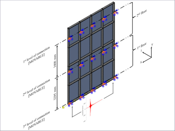
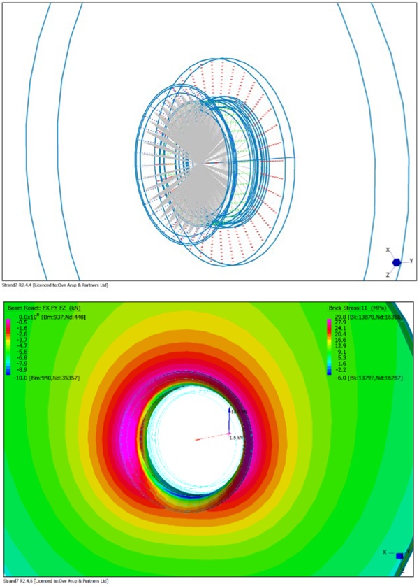
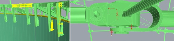
A contemporary detailed analysis model of the original glass connection was created for the purpose of understanding the local behaviour and stress distributions and informing wear and tear analysis to understand the likely causes of the wear and tear identified in the inspections. Volumetric elements were considered for the glass and the fitting while interfaces were modelled with one dimensional contact elements. A precompression of the countersunk part against glass of 5kN was considered in the model. A gravity induced, in -plane force of 10 kN and a wind driven out of plane force of 1.5kN were also considered.
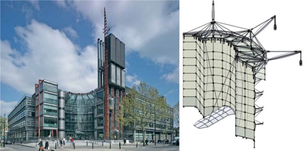
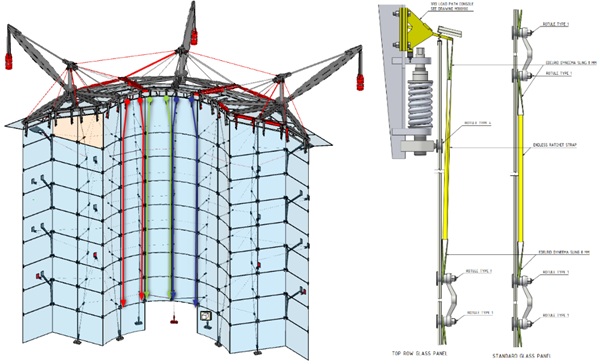
The external roof structure has three primary ‘crane’ tie-backs as described on Figure 2, from which a series of radial or fanning tie-supported beams are supported. These in turn support secondary framing elements, the glass roof, the canopy, and the cable net below.
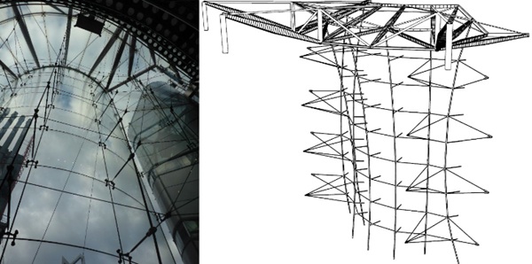
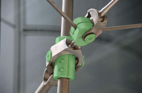
The tensile cable net itself consists of seven main vertical catenary cables with varying drape and pre-tension state. These are prestressed against 8 horizontal cables. The cable net structure, being prestressed applies significant loads at their terminations and is reliant on the integrity of the key connections between the opposing draped cables, an issue that was reviewed critically to address health and safety risks of working in and around a stressed and aged cable net structure. The cable net system also includes a number of local ‘quad’ tie back groups connecting the outer vertical cable pairs to the main structure. The arrangement also includes a number of ‘special conditions’ such as at the interfaces between the curved and flat sections and the corners between adjacent flat surfaces. The structural integrity of the cable net relies both upon the geometric configuration of the cable net and the pre-tension state of the cables. This pairing of reliance informed the proposed structural and geometric surveys and added complexity to the construction sequence and health and safety analysis of working in and around a prestressed structure.
The canopy consists of steel and glass elements and is hung from the roof structure. The canopy appears to float above the entrance and is hung from four cables springing from the roof corners and held down by four tie back cables which brace it down to main structure below. The canopy itself includes a central spine, longitudinal compression tubes (resolving components of force from the supporting cables) and sculptural ‘arms’ that support the glazing above. The canopy glazing is curved and laminated and fixed with point supports.
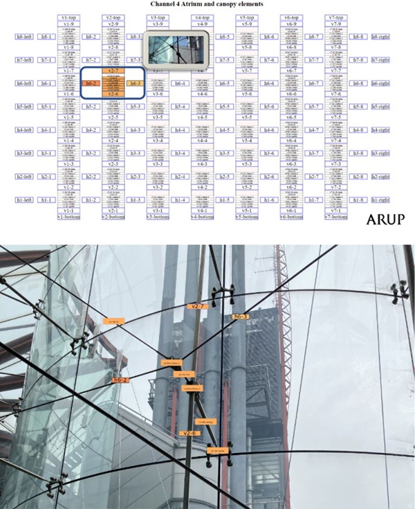
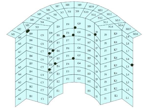
To enable detailed communication and the meticulous association of survey results to individual components a project specific naming convention and component characterisation based on taxonomy principles was established. An interactive project dashboard was then developed by Arup and populated with the photographic survey database provided by Texo with additional project information such as original drawings linked to it so as to organise and manage the large project dataset and allow all parties instant access to key information. The component naming was fully embraced by the contractor in the construction stage, and within the BIM modelling during the disassembly and retrofit. The team considered that this approach greatly assisted in mitigating risks during the refurbishment works.
2. Condition assessment and relevant surveys
To inform the ongoing review a detailed geometric and detailed photographic record of the current condition of the façade as well as the tension state of the support structure and materiality were generated. One of the main outputs from the Texo DSI survey was a detailed photographic record of the atrium which Arup processed into a digital dashboard to allow interested parties rapid access to 8-point views of each and every cable net clamping node such that its condition and state of wear and tear could be rapidly assessed in first instance visually to inform further intrusive investigations. The Texo work also provided point cloud information and a contemporary BIM model. The Revit model presents a clean content structure. All of the elements in the model were modelled as families. Each of these families embeds identity data which enabled Octatube to sort and output schedules of the different elements directly from the Revit model. The glass curtain wall was modelled as a curtain wall element with information embedded to identify each of the panels.
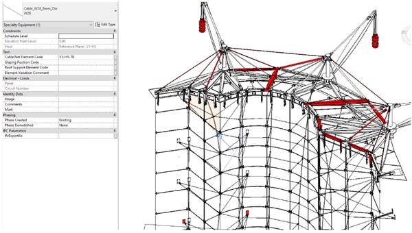
The Revit model presents a clean organization of views and schedules. A view has been created to show and highlight each of the component’s category of the façade. In general, the geometrical resolution and detail of steel connection was good. Imperfections between clamps components, pins and bolts was captured. However, grub screws at the pin caps were omitted. These grub screws in steel pins are important as they prevent the pins from disengaging. This is an important element to add given that misalignments of grub screws could be a sign of movement in the fittings. The Revit model produced provides significant information and assisted the specialist Contractor significantly in the future development of the project. A formal handover of the BIM model to the specialist Contractor was scheduled to allow them to further develop it and integrate their requirements into their final construction documentation.
The image depositary consisted of site visit photography carried out by Permasteelisa (via the initial Abseil studies) Arup, Eiffage and Texo. It included the survey done of the individual survey fixings, mapped in accordance with the project-specific naming convention. The photo survey revealed a number of key wear and tear features whose implications were discussed in detail between Arup, Octatube and the rest of the project team. General comments included:
- Shelling of the glass,
- Surface corrosion at some locations,
- Potential movement in clamps,
- Loosening and loss of some fittings,
- Scratches and other defects,
- Differences in Ground floor (Level 1) to the other panels
- Some glass delamination in laminated glass.
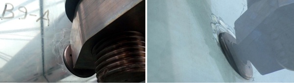
From the original Permasteelisa abseil survey, 10 panels were identified with shelling. After this initial investigation an additional 8 glass panels with and 10 steel fixings in total were identified as compromised.
All shelling occurred around the countersunk hole detail at the point connections including the uppermost fixing.
In multiple locations on the ground floor and within the glazed canopy delamination could be seen in the laminated glass panels. Most of the observed delamination was observed along the edges of the glass panels and in the case of the atrium façade was not generally believed to have a detrimental effect on the structural performance of the glass.
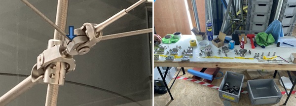
An additional challenge noticed during the detailed cable net inspection was the alignment of clamps, forks, pins and bolts which needed particular attention during the disassembly as the exact condition was not fully known prior to de-tensioning. Only a small fraction of cable net components were replaced with new like-for-like fixings due to their wear and tear and concerns relating to their current precision. Where concerns were attributed to the wear and tear of cable net clamp settings precautionary and ingenious safety over-clamps were installed to ensure that the cable net could not experience a sudden release of energy by a connection losing its interlocked state.
3. Holistic review and common challenges
Due to the lightweight nature of the structure any implications of increased glass weight were considered in detail. The table below summarises the review undertaken. In principle three options were considered for the refurbishment of the atrium glazing as previously discussed in (Lenk, P. 2023):
Table 1: Pros and cons for basic glass replacement options.
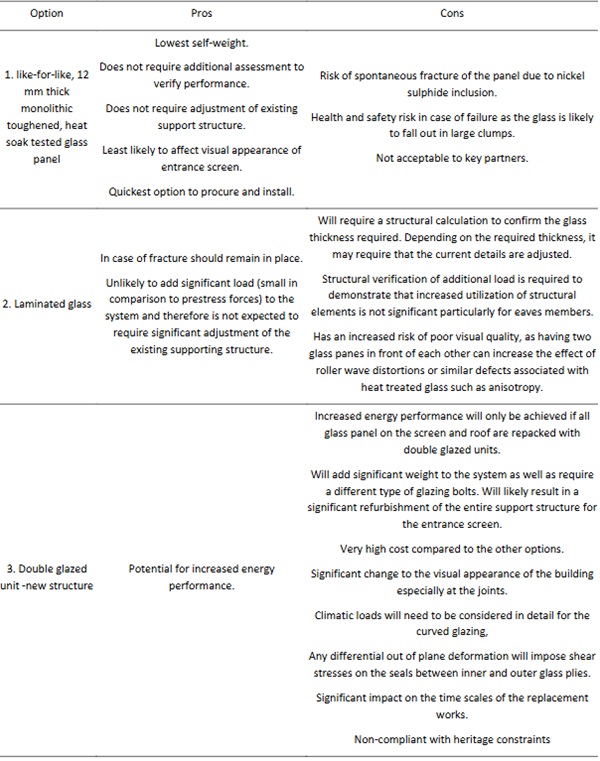
The initial assumption for the remediation of the atrium structure was that the monolithic toughened glazing to the vertical surfaces of the atrium should be dismantled and replaced with laminated toughened or heat-strengthened glass and that the stress state of the cable net be adjusted to bring it back in line with the original designer’s assumptions with adjustment as necessary to account for an increase in the glass dead load applied to the structure.
Given that the initial design had flush point fixings the initial preference was that the remediated option should also use a flush point fixing. However, given that the wear and tear analysis suggested that the original flush point fixings had increased the rate of wear and tear around the fixings and given the general non-availability of flush point fixings the team rejected a flush point fixing in a double laminate option. To fully explore options of providing a flush aesthetic an option with a triple laminate with the outer ply detailed to be flush with a standard point fixing was considered though this was then rejected due in part to its additional embodied carbon but also due to the extra weight, cost, and greater risk of ply-cumulative visual distortions.
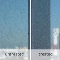
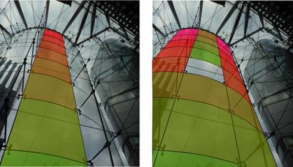
In addition to the above-mentioned findings, the team was also requested to consider overheating, and an excessive glare challenge as reported by the Channel 4 employees working at the building reception. While single glazing offers fewer opportunities for glare and selective filtering of the sun’s energy coating options were considered and a coating was selected and applied.
4. Remediation, Redesign, and Construction
The refurbishment could be seen as a conservation project of the facade, with the goal to improve the robustness of the façade while preserving the appearance as conceived by the original designers.
Rice, P., and Dutton H. (1995) described their methods and design philosophy and explained a number of the difficulties and obstacles encountered. With nine case studies they demonstrated possible applications of the new methods of working with glass with very different design and technical constraints. It describes a period where many details were validated by a series of tests (designed by testing), which led to the minimalism and dematerialization of the details. It was clear that detailed first principles analysis were carried out and debated by the best structural engineers of the time.
Although a lot of the original information was still available from the archives, which provided background on the structural concepts, essential information on the materials and performance testing was missing.
4.1. Filling the knowledge gaps
The first goal was to understand the structural behavior of the façade, crown & cable net in detail, filling in the knowledge gaps with historical research, material investigation, extensive FEM analyses and testing. Many extensive design meetings with Arup and the client, gave the Octatube design team deeper insights into the structural behavior. Step by step, the pieces of the puzzle came together.
During geometrical surveys of the cable net deviations up to 50 mm from the expected position were observed. The prestress survey of the cables also showed a different distribution to that found in the archives. In a FEM model this balance between force and shape (form finding) was studied in detail. After sensitivity analyses a new boundary set of balanced prestress forces was determined. A delicate balance between cable prestress and form finding was completed.
In the next step, the team developed a more robust design for the façade respecting current standards and contemporary health and safety perspectives. The façade has a sophisticated structural interaction of glass panels and stainless-steel parts. Different elements of the façade create structural loops, removing or changing one element could potentially lead to an unstable structure disturbing the delicate interplay. The large quantity of hinges in the system contributes to this.
The reuse of elements, where possible, was requested to pursue a circular economy approach, reduce virgin material extraction, and reduce the climate change impact of the project. Preserving as much of the original geometry, proportion, size and feel of elements and connections due to the recent upgrade to grade II listing was essential. This in combination with the specific shape of the façade led to the decision to retain the façade cable net structure of the original façade installation. However, to increase the post-breakage behavior of the panel and façade the 12 mm single-glazed fully tempered panels were replaced by laminated panels 8.6 mm (fully tempered, SGP). Options to integrate a new dead load path for the glass curtain via dead load rods or cables were considered but rejected due to detailing complexities at the head of the wall, due to the aesthetic degradation that it was thought this would cause to the heritage character of the façade and due to the success of robustness testing.
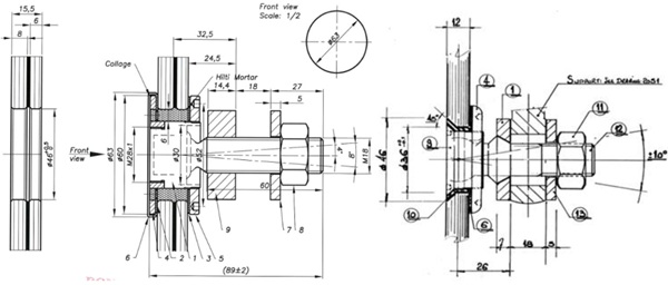
To avoid peak stresses in the glass the countersunk design was abandoned and mortar injection between rotula and glass to activate both plies was adopted. This solution has been extensively studied and tested as described later in this paper.
4.2. Dis-assembly
In the cable net several elements and fixings did not appear fully engaged. The 12 mm fully tempered glass also showed damage around the point fixings. Therefore, a detailed workflow was developed for the dis-assembly of the glass and the controlled de-stressing of the cable net.
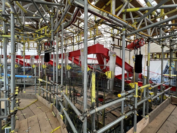
Due to the shape of the façade and the limited space in and around the building, as well as primary structure load-bearing limitations, a complex scaffolding was erected to reach all locations to both sides of the facade. The scaffolding gave temporary horizontal support to the façade and a comfortable working area, shielded from external conditions. To increase safety on site during dis assembly of the glass and destressing the cable net a 3rd load path was created for the glass self-weight, from the steel crown at the top. This 3rd load path was conceived to provide an alternative vertical load in the case of accidental breakage, at a moment when all structural silicone had already been removed. The authors would recommend any team attempting a similar refurbishment to not underestimate the design and installation challenges of erecting a scaffold in a project of this nature and would wish to acknowledge the skill and care of the scaffold team involved in this project.
This additional load path was also used for the installation of the new façade as a part of the temporary works to provide a safety measure during the construction.
Prior to the façade disassembly safety over-clamps were also installed in some locations to provide a secondary connection detail where the surveyed fit of the nodes appeared at risk of loosening to such an extent that there was potentially risk of attachment of key connections.
5. Robustness and redundancy concepts and testing
As stated previously in this paper the glass panels were designed to be suspended from each other transferring the dead load to the roof beams via spring details. The cable structure provides out of plane support only. This differs in concept, from many similar looking point support glass facades. The façade now consists of twelve columns of nine laminated (8.6 mm) glass panels that hang from the roof structure. The top row is hung from the roof structure via spring details. Subsequently, each glass panel is mechanically connected to the panel above by rotulas and two-arm spiders (duos).
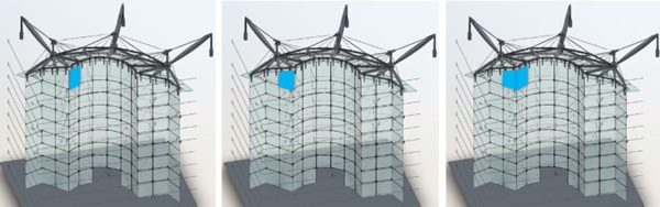
In the façade, the top pane of each row of glass is connected to the roof by two springs. These springs are prestressed, up to the self-weight of the façade that the spring is loaded with. In this way, the springs are vertically fixed points until the load is higher than the self-weight.
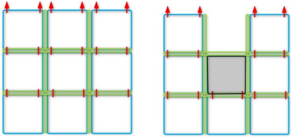
As a consequence, in the hypothetical case of a breakage of glass, the dead load is smoothly and dynamically redistributed over other glass columns, reducing peak stresses during a redistribution event and so reducing the risk of any further or progressive breakage. The rotulas have a hinge, a stainless-steel ball, in the neutral axis of the glass of the glass. Therefore, no bending moment occurs in the glass.
To get a better understanding of the potential redistribution structural FEM calculations were made with “broken” panels. In these calculations the “broken” panels were given no residual capacity for the vertical load path, for this glass chain only the structural sealant (DC993) is active and transfers load to the adjacent glass columns, as a 2nd load path.
To substantiate the structural calculations the concepts of the first and second load paths have been tested in destructive tests.
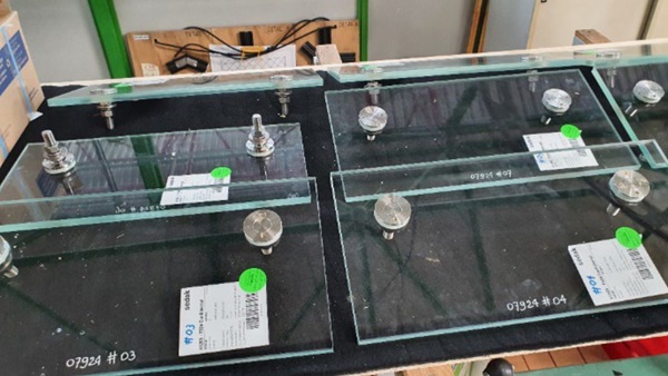
5.1. Primary load path test
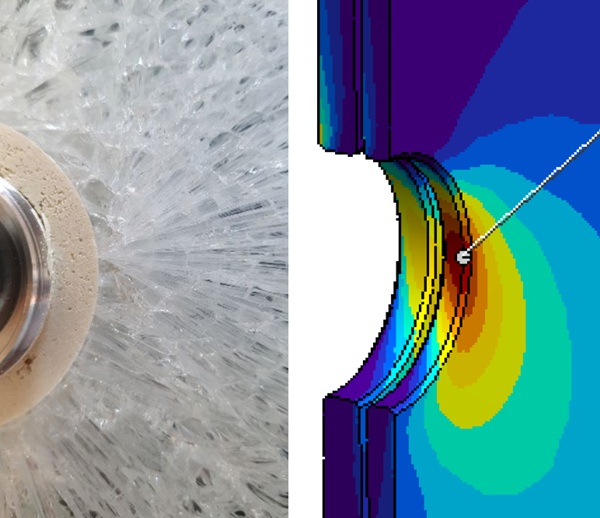
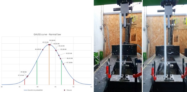
The custom designed point fixing, with the rotula captured with mortar in the glass, was tested. The rotula is subject to high in (glass) plane loads due to the suspension of the façade panels as a chain. According to the results of the tests it can be stated that the special designed rotula with mortar injection is strong enough for this project. The 6 mm glass sheet (inner sheet) broke first followed almost immediately by the 8mm sheet.
The glass initial breakage can be attributed to the point of the highest stress in the calculations as seen in the screenshot of the FEM model showing the location of the highest stress. There were no changes in the appearance of the Hilti resin and no damage observed.
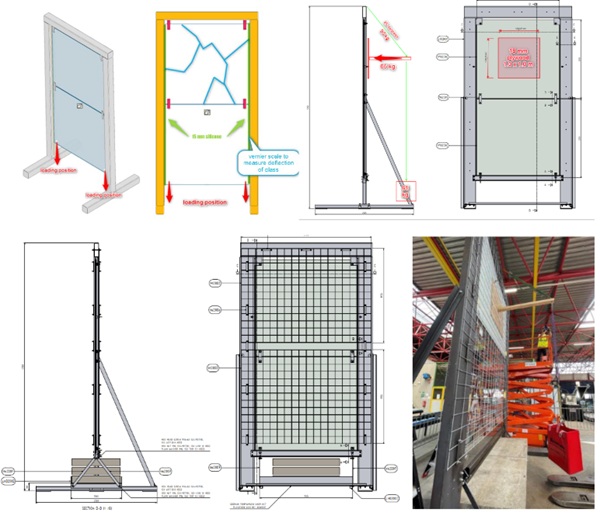
5.2. Secondary load path test
For the 2nd load path, a full-scale test was carried out. With this test, the post breakage behavior of the glass panel and 2nd load path was assessed. The tested sample kept the broken glass in place and allowed us to conclude that robust post-breakage performance should be provided in the event of accidental glass breakage. With the outcome of this test the recommendation for the sequence of replacing the glass panels was further elaborated with the different possible scenarios; different glass panes, time required and necessary steps to replace and or secure the broken glass.
Testing of the broken glass is imperative to prove the safety of the glass unit as whole in the event of an accidental occurrence, as there is no reliable way to calculate the effects caused by the breakage as described in the testing procedure.
With structural calculations a sensitivity analysis has been done in case of breakage of one or two panels. The load distribution is used to determine the loads for this test. The second load path includes the mobilization of DC 993 silicone, to redistribute the dead loads establishing a post breakage load path. This test assessed a glass package with 2 plies: 8.6 mm (fully tempered, SGP).
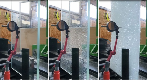
In the test the broken glass panel was connected to the frame by the duos at the top and the vertical joints of the structural silicone DC993. After breakage of the top panel the primary load path which is stiffer is no longer vertically active, the structural silicone adjacent to the glass panel then supports the glass panel, leading to additional vertical deflections. The additional loading in the test was applied to mimic the possible shock effect due to additional vertical deflection of the glass column, suspended below the broken glass panel.
The fours steps of the test:
Step 01 – No breakage
- load on duo 13.2 kN, full glass column (factored)
- Deflection after loading :1.2 mm, after 24 hours: 1.6 mm
Step 02 - 8 mm broken
- load on duo 9.5 kN (unfactored)
- Deflection before breaking 1.2 mm, direct after breaking :1.4 mm, after 24 hours: 1.4 mm
Step 03 - both sheets broken
- load on duo 9.5 kN (unfactored)
- Deflection before breaking 1.4 mm, direct after breaking: 3.2 mm, after 24 hours: 3.9 mm
Step 04 – both sheets broken – only dead load and 20 % of the wind load, 5 minutes.
All the panes were broken, and a horizontal load was applied on the broken glass. The broken glass remained in place and didn’t fall out.
The panel slightly deformed during the breaking of the plies. The panel further deformed when the horizontal load was applied. The glass didn’t break off around the point fixing. Even though in the test there was allowed for more deformation than is to be expected in practice, the silicone was able to carry the load. The second load path through the silicone was activated and functioned fully.
The glass and silicone system successfully passed the full-scale post breakage behavior test.
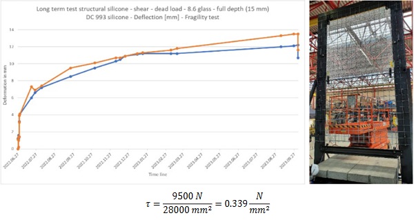
Subsequent to this test 9.5 kN load was kept in place for a long-term test outside of the project specification to gather hard to obtain information about post failure behavior of structural glass systems. The permanent stress in the silicone was 0.34 N/mm2 and initial vertical deformation of 4mm. For comparison the shear stress resistance value for silicone DC993 are available for short (5 sec, 0.11 N/mm2) or long term loading (50 year, 0.011 N/mm2). After 15 months, silicone creeped ~ 12 mm and the load came to rest on the floor, see deflection in figure below, there was no rupture or damage of the silicone observed.
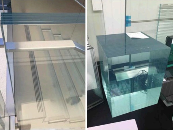
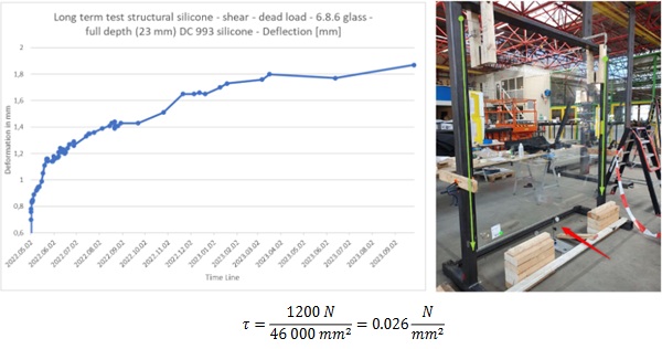
The maximum expected load on the structural silicone in the secondary load path is lower than that tested. The structural silicone is only loaded by the adjacent glass panel. Since there is no stiffness data available, for the structural silicone DC993, for longer time periods, another test was performed in the factory of Octatube. The deformation of the façade using this 2nd load path was verified. A three layered single glass (6.8.6 mm HS.FT.FT + SGP interlayer) of dimensions 2100 mm x 2000 mm was siliconed to the vertical edges in a steel frame. With a bite of 15 mm, covering the full glass depth 23 mm. The test results can be considered equivalent to the two plies façade glass, since the glass has a lower weight, but it also has less adhesion surface available.
The glass deflected 0.7 mm immediately after the test started. According to FE Analysis, the expected deflection was 0.6 mm. A long term deformation of up to 2 mm was noted after 15 months. For both tests a similar deflection profile over time was observed.
6. Conclusion
Building materials incorporated into façade systems can experience various degrees of mechanical degradation due to aging and wear and tear during their service life. Building owners and their agents should ensure that facades are regularly monitored and maintained so as to prolong their life. The engineer lead prolongation of facade systems will both reduce the cumulative embodied carbon footprint of façade installations and the capital cost expenditure over the lifetime of a project while at the same time ensure the safe and functional provision of service by a façade installation.
In particular, prestressed cable net façade systems and high-tech architecture require a detailed structural understanding and expertise to ensure that the facade is maintained in accordance with the assumptions of the original designer. It is important that the maintenance team are conversant with the original designer’s assumptions.
Refurbishment projects require even greater levels of collaboration than new-build projects with planning and cost allowances made for unforeseen events or unexpected findings. Meticulous surveys and appropriate risk planning prior to carrying out any work can reduce uncertainties, reduce the likelihood of unexpected events, improve health and safety, and generally reduce risk.
Structural testing remains a key part of detailed façade design for bespoke and unusual façade systems and the agreement of test sequence and pass/failure criteria prior to testing is essential to determine adequate safety expectations and confirm the engineers’ assumptions. Tension systems have an enormous amount of stored energy within them and thorough attention to health and safety considerations when working in and around them is essential. Scaffolding for safe working is a key ingredient to success. It is recommended that any designer carrying out new-build projects carefully consider refurbishment prior to an initial build to facilitate the future operations to the façade, to improve circularity and reduce the embodied carbon impacts of disassembly or refurbishment.
Acknowledgements
The success of any project requires great collaboration between many parties. The authors would in particular wish to acknowledge the contributions of the client, Wheelers, Epiphany, Arup Fire, Arup access and maintenance, Arup project management, Arup Architecture, RSHP Architects, Eiffel, Permasteelisa, Texo DSI, Base, and the local residents ’association.
References
Rice, P., Dutton, H.: Structural Glass, Taylor & Francis, 2nd edition, London, UK (1995)
Addis, B.: The Art of the Structural Engineer, ellipsis London Ltd; First Edition, London, UK (1994)
IStructE, : Structural Use of Glass in Buildings, First Edition, Institution of Structural Engineers, London, UK, (1999)
Sudjic,D.: Richard Rogers Partnership, Channel 4 Headquarters, Blueprint Media, London, UK (1996)
Lenk, P.: Glass in buildings – Renovation, Rehabilitation or Restoration? Proceedings of Glass Performance Days, Tampere Finland (2023)