
Article Information
- Digital Object Identifier (DOI): 10.47982/cgc.9.570
- Published by Challenging Glass, on behalf of the author(s), at Stichting OpenAccess.
- Published as part of the peer-reviewed Challenging Glass Conference Proceedings, Volume 9, June 2024, 10.47982/cgc.9
- Editors: Christian Louter, Freek Bos & Jan Belis
- This work is licensed under a Creative Commons Attribution 4.0 International (CC BY 4.0) license.
- Copyright © 2024 with the author(s)
Authors:
- Barbara Siebert - Dr. Siebert and Partner Consulting Engineers PartGmbB
- Geralt Siebert - University of the Bundeswehr Munich

Abstract
Photovoltaics in façades are currently enjoying great popularity, also as a way of contributing to renewable energy production. There are various subsidy programmes to promote the installation of photovoltaics. Two "worlds" meet here, the world of electricity and the world of construction. In casephotovoltaic modules are CE-labelled, the basis for this is not the European Construction Products Regulation but a low-voltage directive. Taking a closer look at the set-up of these modules, one very often finds unregulated construction products: Thin glass, no PVB as an interlayer but other materials, glued constructions - in some cases also point-glued in the form of backrails. With photovoltaic cells a laminated safety glass turns to simple laminated glass. There are also more and more applications that not only act as cladding, but are also installed as fall protection or "overhead". This paper begins with an overview of the different types of modules and their applications. It discusses building regulations including the necessary structural analysis and testing verifications. Another important aspect is the anchoring to the building. Until now most applications are standard applications with framed panels on roofs or installations on fields. More and more attractive applications from the architectural point of view are built or are under construction. Finally, some projects are presented.
1.Introduction
The integration of photovoltaic (PV) elements into the building envelope not only contributes to environmentally friendly energy generation and thus to the reduction of CO2 emissions, but also offers new design possibilities from an architectural point of view. Another advantage is that the PV elements in roofs or façades can take over the basic functions of conventional façade elements, such as sun protection, sound insulation or thermal insulation.
Progress is constantly being made in the development of PV elements, particularly in terms of improving efficiency and reducing manufacturing costs and energy consumption during production.
In the meantime, PV elements are also becoming increasingly popular in architecture and must therefore also meet the requirements for building and facades.
Due to the increasing efficiency of the modules, the arrangement of PV modules also makes sense in installation situations and orientations that are not “optimal”: On north-facing façades, on glass roofs, in the parapet area of mullion-transom façades. In the case of glass roofs, the sometimes desired shading effect is also a positive factor.
2. Building legislation and background information
PV modules are also subject to requirements imposed by building authorities.
In Europe, there are only very few regulations on the use of photovoltaics as a building product.
The regulations in Germany initially state that the following modules can be used without verification of usability with regard to the essential characteristic "mechanical strength and stability":
- PV modules with mechanically held top glass cover surfaces and a maximum single module area of up to 2.0 m² when used in the roof area with an inclination angle ≤ 75°,
- PV modules without glass cover surfaces when used in the roof area,
- PV modules with mechanically held glass cover surfaces and a maximum individual module surface area of up to 2.0 m² when used in building-independent solar energy systems in publicly inaccessible areas.
In future, the limit will be raised from 2m² to 3m². However, these simplifications do not apply to most applications in the façade and building envelope.
If the above simplifications do not apply, verification of application is required, e.g. according to the design standards for glass or aluminum. In the case of unregulated constructions (e.g. bonded constructions), a so-called project-related or general building permit is required in Germany.
German building law (MVVTB) classifies PV modules as technical building equipment that have a CE marking, but not according to the Construction Products Regulation, but exclusively according to the EU Low Voltage Directive (2014/35/EU) as electrical equipment.
CE marking is based on the electrotechnical standard DIN EN IEC 61730-1 and -2, which does not allow PV modules to be assessed in terms of mechanical strength, stability and fire protection in accordance with the established safety and verification concepts of the construction industry.
Accordingly, the CE marking does not guarantee that the basic requirements of the Construction Products Regulation (including mechanical strength and stability, fire protection, but also safety of use and accessibility, sound insulation and energy saving, health, environmental protection and resource conservation) are fulfilled when installing PV modules in buildings.
Thus, the CE marking of the PV modules does not specify essential product characteristics as a construction product, such as strength and fracture behaviour or classification of fire behaviour, and a separate verification of usability is required in general.
A good insight into the building regulations can be found in the: „Allianz Bauwerksintegrierte Photovoltaik BIPV: Technische Baubestimmungen für PV-Module als Bauprodukte und zur Verwendung in Bauarten, Bauordnungsrechtliche Vorgaben zu Produkt- und Anwendungsregeln“ (BIPV 2023). The requirements for fire protection, mechanical strength and stability are assigned to the respective applications and the required verification is listed.
3. PV-Modules
3.1. Module types
First of all, a classification of modules is made:
Thin layer:
- amorphous, non-crystalline or other semiconductor materials such as copper indium gallium diselenide (CIGS) and cadmium telluride (CdTe) and also organic solar cells made from hydrocarbon compounds
- Very thin, possible for flexible modules
- Efficiency lower than that of crystalline modules
Monocrystalline / polycrystalline:
- Efficiency better than thin-film modules
Photovoltaics can be translucent, coloured, metal-look or patterned. The first pilot projects with transparent PV windows already exist. The market is an extremely fast-developing field.
3.2. Glass and laminate
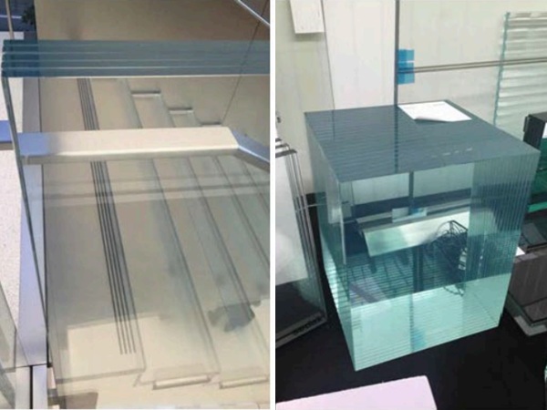
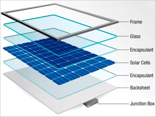
The glass panes used are usually very thin, sometimes plastic is used as a cover pane or a single layer with photovoltaics vapor-deposited on the back. In most cases, thin laminated glass panes are used. The intermediate layer in which the photovoltaics are embedded is made of PVB films, EVA films or now also silicones. Due to the special glass setup, it is not classified as laminated safety glass but only laminated glass. This can be a difficult point in the planning and approvement process.
Due to the very thin glass, often only 2 or 3 mm, it often is not possible to classify it as toughened safety glass or heat-strengthened safety glass, it is often something in between. Appropriate tests are required to determine the bending tensile strength.
3.3. Bearing
The (supposedly) simple modules are mounted linear on 4 sides in an aluminum frame. The installation depth is often very small here, and the glass often is glued in additionally. As soon as a load-bearing bonding is used, the verification becomes more complicated, as it is an unregulated construction. The adhesive used is often not known or changing, so that verification in accordance with ETAG 002 (previously) or EAD 090010-00-0404 (currently) is hardly possible.
There are systems with special punctual façade clamps which are suitable for rear-ventilated façades or systems with bonded backrails and a completely flush appearance. The latter are the most complex to design.
4. Testing
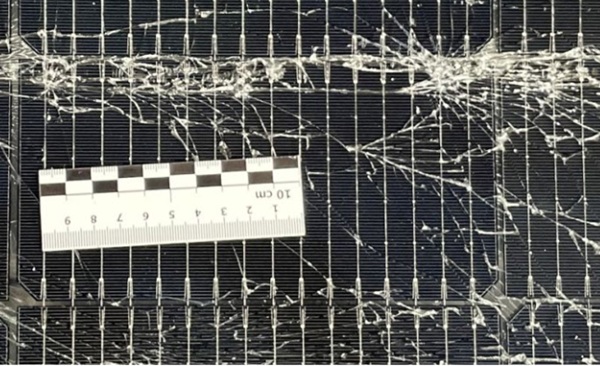
In addition to the usual tests for glass structures, such as impact resistance or residual load resistance, further tests are required.
- Proof of building material class B2 according to DIN 4102-1 or class E according to DIN EN 13501-1
- Four-point bending test for determination of glass strength
- Identification of the intermediate material, DIN EN ISO 527 (tensile strength, elongation at break)
- Material and process characterization, degree of curing/gel content according to DIN EN 62788-1 -6
- Resistance, DIN EN ISO 12543-4:2022-03, DIN EN ISO 12543-2:2022-03
- Soft impact in opened condition, comparative test based on DIN EN 12600
- Adhesion, peel test based on DIN EN ISO 8510-2
- Residual load-bearing capacity according to DIN 18008-1, 2020
5. Analysis
5.1. Framed Modules
Framed Modules are very simple to calculate, but some points make it more difficult:
- Large deflections because of thin glass
- Frame is often glued together with the glass
5.2. Systems with backrails: ETAG 002 (previously) or EAD 090010-00-0404 (currently)
The ETAG 002 (previously) or EAD 090010-00-0404 (currently) are one of the few normative regulations for structural bonding in the façade industry. The following boundary conditions apply to an application:
- Anodized aluminium or stainless steel as bonding partner for the glass
- 4-sided or 2-sided linear bonding
- Adhesive joint width between 6mm and 20mm
- Adhesive joint thickness at least 4mm
- Maximum deflection of substructure is L/300
- Maximum deflection in the middle of the pane is b/100
- Assignment of types I to IV (in Germany only I and II)
- Global method factor 6.0
- Local effects / multidimensional stress states not taken into account
This excludes the most common applications, especially those with backrails.
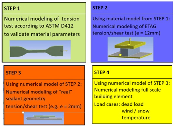
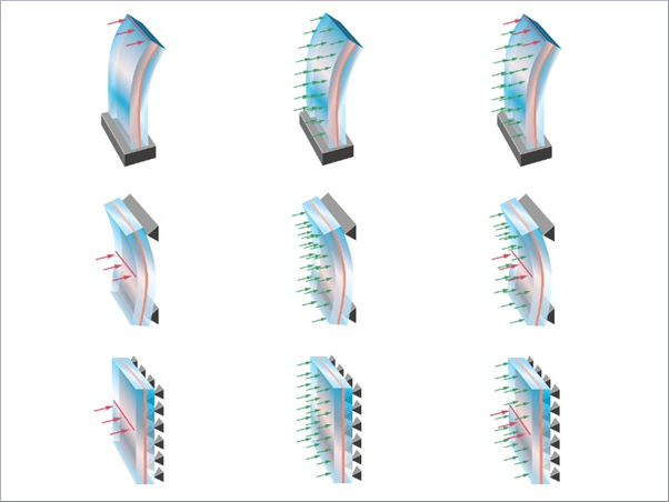
5.3. Systems with backrails: “true stress” Method
By using „true stress“ (FE analysis) instead of „engineering stress“ for identifying a „true“ safety factor and local stress peaks allows to transfer ETAG 002 design rules to
1. alternative sealant dimensions (thickness)
and/or
2.variable locations / layout of bonding (not 4 sided)
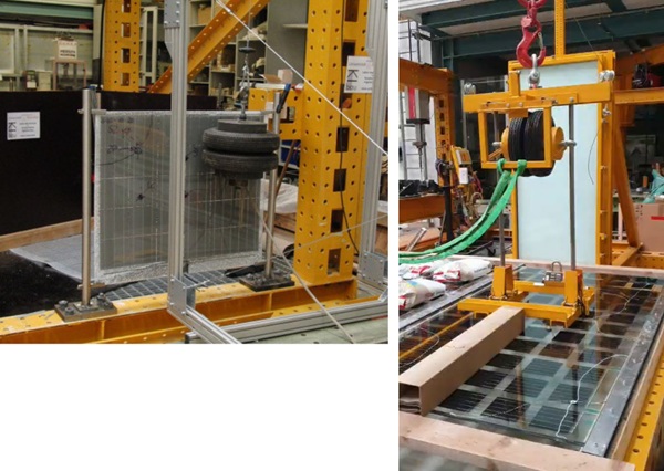
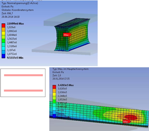
For FEA a step by step verification and validation based on experimental data was developed, see the following figures.
5.4. Anchoring to the building
In order to be able to offer PV systems cheaply, the substructure and its connections often are designed to minimum cost. Unregulated fasteners, rivets or clamp connections are used often, which makes the effort for mathematical verifications more difficult.
6. Examples
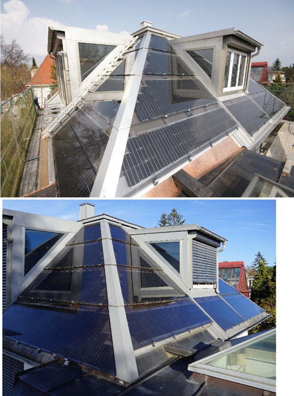
6.1. Solar roof private House in Munich
This example was already presented in challenging Glass 3 (Siebert B. 2012).
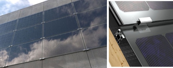
For the rehabilitation of a private House in Munich a new system for the roof was developed. Instead of roof ties and additional solar panels, the solar panels were fixed direct to the wooden substructure with special clamps. A leak-proof covering behind the PV-elements is not necessary. The solar panels are situated overlapped like the tiles of a classical roof. Advantage is the ventilation of the system with a better efficiency, the reducing of costs because of only one layer of covering and a very fast installation because of large scale elements. The roof was installed end of 2011.
After 12 years of long-term experience, an initial positive conclusion can be drawn: Due to the use of glass-glass modules, all modules are intact, the efficiency is unchanged and the insulation shows no signs of degradation.
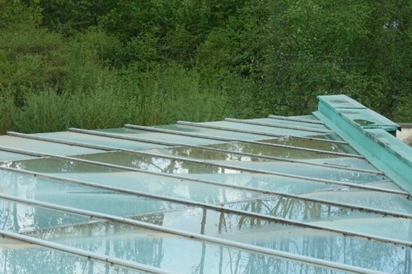
6.2. Overhead glazing foyer of an ecological education center
The second example deals with a glass roof as a mullion-transom construction, which has the usual challenges of glass roofs: Insufficient slope, defects in the inner sealing level and corresponding damage to the glazing and timber construction due to water penetration.
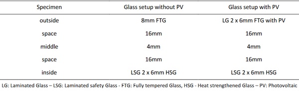
The refurbishment concept provides for a new glass roof with the integration of photovoltaics. Part of the multi-pane insulating glazing will be fitted with photovoltaics. The structural analysis and proof of usability is relatively simple, as instead of the usual outer monolithic toughened safety glass pane, a laminated safety glass made of toughened safety glass with embedded photovoltaic cells is installed.
Table 1: Glass setup with and without PV.
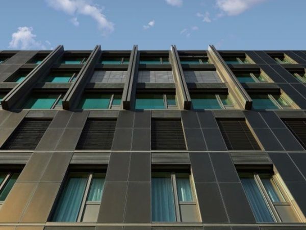
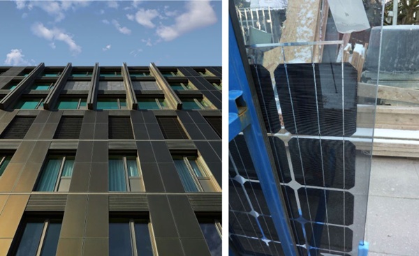
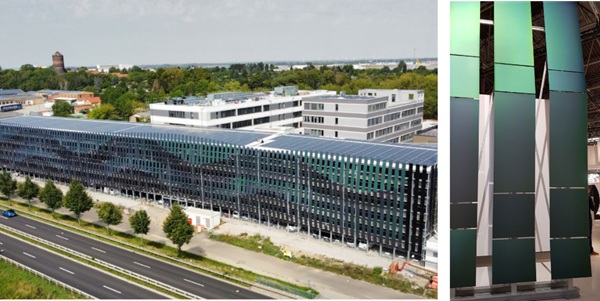
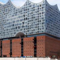
6.3. Facade of a parking garage at Airport Leipzig
Frameless PV modules were planned for the south façade of the DHL parking garage at Leipzig-Halle Airport. For reasons of fire protection, appropriate cross-sections are required for ventilation, i.e. the modules are mounted with large vertical gaps. They are also mounted at different inclinations in order to achieve the architecturally desired wave appearance. Although the planned system has a general type approval, it does not cover all shortened modules. A project-specific type approval therefore had to be obtained on the basis of an expert opinion.
7. Conclusion
Photovoltaic systems in the building envelope are very often underestimated from a building legislation and structural engineering perspective. Supposedly simple standard products are often more difficult to verify than customized constructions.
Verification of usability is required for almost all applications. Photovoltaic systems also require all planning phases and the involvement of façade planners, structural engineers, solar planners and electrical specialists.
References
BIPV 2023: Allianz Bauwerksintegrierte Photovoltaik BIPV: Technische Baubestimmungen für PV-Module als Bauprodukte und zur Verwendung in Bauarten, Bauordnungsrechtliche Vorgaben zu Produkt- und Anwendungsregeln. January 2023
Maniatis, I.: Innovatives Bauen mit PV-Elementen, OTTI 2009
Maniatis, I., Siebert, G.: Systems for fixing of solar panels, GPD Glass Performance days, 2009 Tampere
Siebert, B.: Building integrated Photovotalics, Challenging Glass 3, 2012 Delft
https://pauli.de
https://avancis.de
DIN 18008-1:2020-05: Glas im Bauwesen – Bemessungs- und Konstruktionsregeln – Teil 1: Begriffe und allgemeine Grundlagen
DIN 18008-2:2020-05: Glas im Bauwesen – Bemessungs- und Konstruktionsregeln – Teil 2: Linienförmig gelagerte Verglasungen
DIN 18008-3:2013-07: Glas im Bauwesen – Bemessungs- und Konstruktionsregeln – Teil 3: Punktförmig gelagerte Verglasungen
DIN 18008-4:2010-12: Glas im Bauwesen – Bemessungs- und Konstruktionsregeln – Teil 4: Zusatzanforderungen an absturzsichernde Verglasungen
DIN 18008-5:2013-07: Glas im Bauwesen – Bemessungs- und Konstruktionsregeln – Teil 5: Zusatzanforderungen an begehbare Verglasungen
DIN 18008-6:2018-02: Glas im Bauwesen – Bemessungs- und Konstruktionsregeln – Teil 6: Zusatzanforderungen an zu Instandhaltungsmaßnahmen betretbare Verglasungen und an durchsturzsichere Verglasungen
CEN/TS 19100-1 2021 (E): Entwurfsfassung Eurocode Glas


Comments
Really cool how solar panels are being used in building walls now! Not only do they help with energy, but they also look great and serve a purpose. Can’t wait to see more of this in the future! Autoglass