Challenging Glass 6
Conference on Architectural and Structural Applications of Glass
Louter, Bos, Belis, Veer, Nijsse (Eds.), Delft University of Technology, May 2018.
Copyright © with the authors. All rights reserved.
ISBN 978-94-6366-044-0, https://doi.org/10.7480/cgc.6.2127
Authors:
Terry McDonnell - Klein & Hoffman
Connor Bruns - Simpson Gumpertz & Heger
Oliver Lahr - Roschmann Group
Patrice Couret - Roschmann Group
The owner of a 1970s, 24-story commercial office tower in Ottawa, Canada sought to rejuvenate their main lobby with a new glass entry wall. The wall’s purpose is to provide a notable, grand entryway for the re-development of a commercial podium on a main thoroughfare. The final design featured a 12 m tall by 35 m long curving glass fin wall. The height of the wall is broken up into two sections. The first is a 9 m tall section between the ground floor and a third-floor terrace that provides the main building with a new front entrance, including a double-height space. The second is a cantilevered 3 m tall balustrade that creates a new third floor terrace.
The glass fins between the ground floor and third floor terrace are continuous, triple-laminated panels free of splices. The curved panels have a 30 m curvature radius and feature a ceramic frit to prevent bird strikes and promote environmental sensitivity. In addition, the panels are insulated glass units (IGUs) with a low-emissivity coating (low-e) to meet the City of Ottawa’s energy standards and the expected interior comfort of top tier retail and office space within the city. Furthermore, the glass panels are supported at discrete points, so the team used a composite resin as the laminate for the interior and exterior lites to maintain the cold bent curvature radius.
1.Introduction
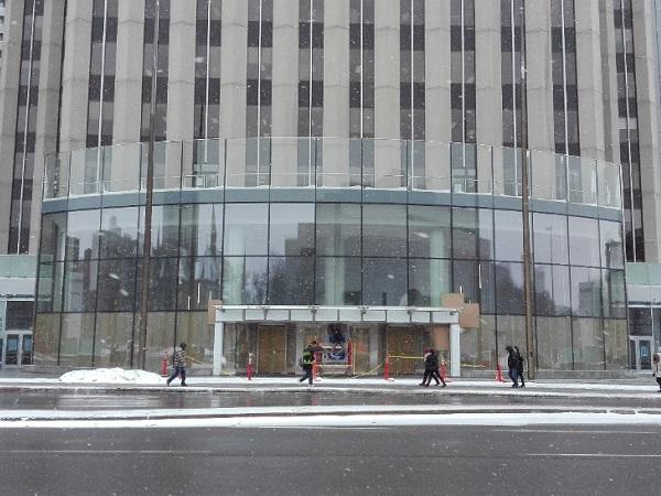
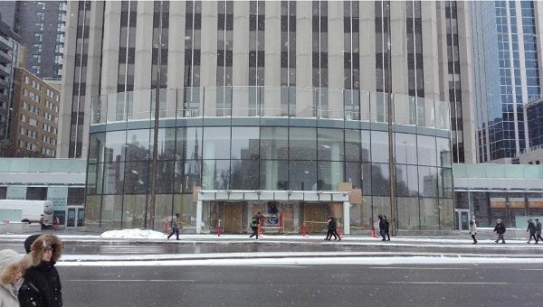
“Going ahead of the Curve” is what the advertisement states outside of newly remodeled, Class A office building at 160 Elgin Street in Ottawa, Canada. The building is a 26-floor office building near major government, retail, and museum attractions that includes a two-story retail podium and an underground parking level. Recently, the Ownerdecided to completely remodel the retail podium and include a new grand entryway to announce the upgraded space inside in conjunction with Ottawa 2017, a celebration of Canada’s 150th year as a nation. The Architect envisioned a transparent entryway that would be a “one of a kind transparent jewel” for the City of Ottawa. The idea conceived was a completely transparent curved entry that would extend from building corner to corner and extend beyond the height of the two-story podium (Figure 1). This would make the interior and exterior indistinguishable from each other, so much more so with a curving glass surface that would not break up the optical clarity at joints like a segmented entryway would.
The glass wall design team includes the Architect (Petroff Partnership Architects) and the glass engineer (Simpson Gumpertz & Heger). The construction team includes the general contractor (EllisDon), the specialty glass contractor (Roschmann Group), and specialty engineer (RJC). The specialty glass contractor engaged Schollglas as the glass manufacturer and fabricator for the exterior glass panels. Simpson Gumpertz & Heger (SGH) and Roschmann had extensive collaboration to achieve the goals set out by the building Owner (H&R REIT) and the Architect.
![Fig. 1 The 160 Elgin Glass Wall Design Rendering[1]](/sites/default/files/inline-images/Fig1_182.jpg)
2.Project Background
The glass entryway measures approximately 35 m in chord length and 12 m tall, and includes an exterior curvature radius of 30 m (Figure 2). The initial concept included glass fins every 2340 mm that would support the glass panels off the ground and resist the wind loads between the ground floor plaza level and third floor roof terrace. The design developed to include a nearly 3 m tall curved glass screen wall above the third floor that would allow for public roof top access for the primary tenant on the third floor. The curving glass panel wall would need to fly by the third-floorslab so that it appeared as one single curving design feature both above and below the third floor.

Initial design concepts contemplated four levels of approximately 2740 mm by 2340 mm curving insulated glass unit (IGU) panels. As the design progressed, the glass panels had to achieve more than a curving geometry to meet the project goals. The desire for the base of the glass wall to intersect the plaza level (where building guests could walk up to it on both the interior and exterior) drove the need for laminated glass on both sides of the IGU panels for safety. After multiple discussions with the project mechanical engineer, it became clear that the IGU required both an Argon-filled airspace and a low emissivity (low-e) coating to meet the energy code within the city of Ottawa.
Finally, late in the design, the building Owner requested design options to prevent bird strikes, in order to show a positive ecological benefit within the project. SGH and Petroff incorporated a silkscreen-applied ceramic frit into the curving IGU panel design. The often-competing design demands on the wall, which now included high-quality curved glass, high transparency, energy efficient IGU, laminated safety glass on each side of the IGU, a low-e coating, and a ceramic frit, made the design, fabrication, and construction of this one-of-a-kind grand entry wall a unique challenge.
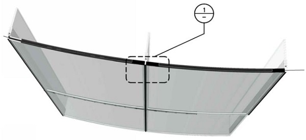
The structural backup system for the curved glass panels is gravity-loaded glass fins. The fins are laminated glass beam-columns that are supported for gravity loads at the ground floor and supported for lateral loads at the third floor. The third-floor pin connection incorporates a vertical slotted hole that allows movement. The fins support the gravity load of two rows of curved IGU panels. Each panel in its final configuration weighs approximately 550 kilograms. In addition, the fins have to resist the wind load normal to the curving surface of the IGU panels. The combined gravity and wind loads required three lites of 12 mm laminated glass that are 400 mm deep. The laminate material for the fins is Saflex® DG 41 structural interlayer. Figure 3 shows an isometric design detail of the curved glass IGU panels and glass fin.
3.Design Challenges
The glass wall design evolved from an early concept to highly detailed installation drawings. The design team and Owner studied various glass configurations and connection types throughout the duration of the project. Below, we describe in detail more notable design challenges associated with meeting the architectural vision and providing a high-performing wall.
3.1.Hidden Connections
The deign team spent most of their time early in the project on the glass panel to glass fin connection. At first, the Architect desired a conventional point-supported connection. SGH explored the compatibility of this connection type to curved glass and found limits on spacer reliability around a point support. Spacer manufacturers expressed concern about the lack of water infiltration testing on point-supported seals for curved glass through-wall fasteners. The design and construction team developed an alternative connection that reduced the concerns associated with traditional point supports by hiding the connections from view, and from the exterior elements. We accomplished this by burying the connections inside the vertical and horizontal wall panel joints.
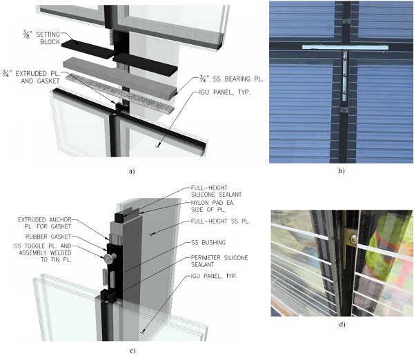
The gravity connections evolved into stiffened ‘wing plates’. The wing plates started out 20 mm thick horizontal plate. The purpose of the wing plate is to flare out from the stainless steel glass fin capture plate and create a shelf for the upper panels of curved glass to sit on. This stainless-steel plate is installed inside the intersection of a sealant joint between four panels (Figure 4a). The wings would be a bearing support for each end of two adjacent panels. Figure 4a shows an exploded axonometric of the wing plate during the design phase. During the installation drawing phase, the team refined the wing plate further by adding a 12 mm vertical stiffener, thereby reducing the wing platethickness from 20 mm to 12 mm. The vertical stiffener is embedded within the vertical joint below the wing plate.The specialty contractor fabricated the “tee” shape using built-up stainless steel pieces, and then screwed the assembly into the glass fin capture plate (Figure 4b).
A series of toggled connections buried inside the vertical joints transfer the lateral wind loads to the glass fins. These stainless-steel toggles engage the sides of every IGU at stainless-steel bushings that were inserted in the sides of the panel during the fabrication of the IGU silicone seal. Roschmann suggested the Raico Therm+ S-I system during the shop drawing development process. This system provides a thermal break and allows the vertical sealant joint to be slightly narrower than the original SGH design due to the use of a rectangular toggle. The stainless steel toggles are spaced no more than 400 mm apart along the glass fin.
As shown in the series of diagrams and pictures below, the wing plate bearing connection and lateral toggle connectionare both securely buried within the sealant joints between the curved glass panels and ‘disappear from view’ once the wall is complete
3.2.Curved Glass Fabrication
When creating curved glass there are multiple fabrication techniques available for the design and construction team to pursue. Each option has benefits and risks that must be thoroughly explored prior to coming to a decision. Below is a list of the fabrication techniques explored during the design phase of the 160 Elgin curved glass wall. Please note that the authors use the terms bending and curving interchangeably as synonyms.
a) Hot Bending and Annealing – A mold is created with the inside surface of the mold representing the final condition of the exterior face of the glass panel. After heating the glass panel up to 600 °C (1,100 F), gravity will “sag” the plasticized glass into the desired form defined by the mold. After “sagging,” the glass panel is cooled down slowly to anneal it. An annealed curved glass panel has similar strength and optical qualities to annealed flat glass. The benefits attributed to this process include smaller curve radii, and compound-curved geometries such as those on car windshields. The limits attributed to this process include the quality of the mold, and requirements for thicker annealed only glass panels to achieve the desired result.
b) Hot bending in the tempering furnace (Also called online bending) - Heat treated glass is curved as part of the heat strengthening process very similar to a flat, heat-treated glass panel. The process gives glass the mechanical and thermal strength and known fragmentation behavior of heat treated or fully tempered glass. The benefits attributed to this process are similar to the Hot Bending and Annealing process, and include heat treated glass. The limits attributed to this process include only cylindrical shaped panels and increased risk for optical distortion.
c) Cold bending over rigid framework - This type of cold bending involves use of a shear-flexible PVB interlayer to bond the panes of glass together so that the resultant laminated lites are more flexible for long term loading and may be bent into a shape over a form. Laminating (autoclaving) after cold bending the glass is possible. However, the curve must be mechanically maintained on the panel throughout the remainder of fabrication and at its final condition, usually along the opposing curved edges of the glass panel. If at any point in its lifetime the glass panel is relieved from its curved shape, then the monolithic glass will straighten, or a laminate will un-wind and straighten as well. This process is limited to heat treated glass because the glass must resist permanentresidual stresses due to the cold bending process.
d) Pre bending during lamination - This process involves bending the individual panes of a glass laminate prior to laminating and subsequently laminating those lites into a new permanently curved geometry. The finished laminated pane retains its bent shape after laminating (autoclaving) without the need for a supporting framework to help the glass retain its shape. This can only be accomplished with very stiff laminates such as an ionoplast or a resin based laminate. The unique advantage of pre-bending laminated glass is primarily its better optical quality due to fewer distortions and reflections. The minimum curvature radius is about 1500 times the thickness of the glass (e.g., 10mm: curvature radius 15m). Similar to the cold bending over rigid framework option, this process is limited to heat treated glass (heat strengthened or fully tempered) because of the larger stresses initially induced within the glass bending process.
For this project, the design and construction team determined that the pre-bending during lamination option is the most appropriate procedure. The laminate we used is a resin called GEWE-composite® and is installed by pouring itbetween panes and cures, instead of requiring another pass through the autoclave. The laminate and bending process could be performed at the glass manufacturing plant immediately after heat treatment.
3.3.Interaction with the Base Building
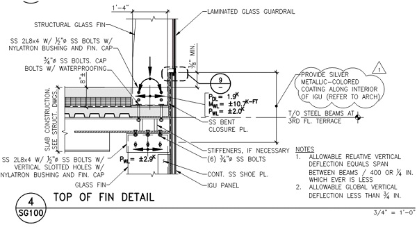
The new glass entryway spans between the existing supported plaza level (ground floor) and the new third floor terrace. The existing plaza level structure is a conventionally reinforced concrete beam and slab system over a basement andretrofitted with drilled piles to support the glass fins. The new extended third floor terrace structure comprises tapered structural steel beams that cantilever radially from the existing third floor framing to support the new terrace spaceand to brace the tops of the glass fins. The detailing of the top-of-fin connection and the expansion joint between the IGU wall panels and glass balustrade panels accommodates the combination of superimposed dead loads, live loads, and snow loads that may occur at the ground floor and third floor terrace, as well as the glass thermal loads. The design drawings specified vertical slotted holes in the glass fin connection as well as a 38mm wide expansion joint to accommodate the anticipated building movement (Figures 5a and 5b).
When defining the required movement in the connection at the third floor, the design team also considered the third-floor terrace construction sequence and incremental superimposed dead loading from the structural slab, topping slab, glass balustrade system, and stone pavers. Early construction coordination meetings included discussions regarding the critical sequencing, resulting in the implementation of a monitoring program to measure the base building structure deflections during the construction sequence.
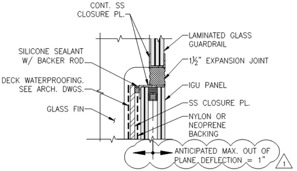
4.Manufacturing and Construction Challenges
The manufacturing and construction process posed additional challenges to maintain the specified project tolerances, verify the wall performance, and adapt to the combination of existing building conditions and variability in tolerances between high-end structural glass and conventional construction.
4.1.Fabrication of the IGU Panels
The fabrication process of the complete IGU panels was truly a delicate and well-planned feat for the project. The entire process was performed by Schollglas in Germany. As discussed above not only were the panels required to be curved and an IGU, but laminations on both sides of the IGU were required to meet safety glass requirements at the base of the wall, a low-e coating was required to meet the local energy codes, and a frit pattern that prevented bird strikes was required by the building Owner for their commitment to ecological stewardship. The final glass panel make-up is shown below, and a step by step approach to the panel fabrication is discussed below;
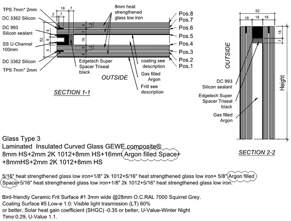
a) The glass was first manufactured and fully tempered.
b) The low-e coating (ClimaGuard 1.0 T by Guardian Glass, USA) was then applied to the appropriate flat lite on what would eventually be position #5.
c) The enamel based frit was also applied to the appropriate flat lite on what would eventually be position #1 using a silk screen process to provide a horizontal stripe pattern and color match to RAL 7000, Squirrel Grey.
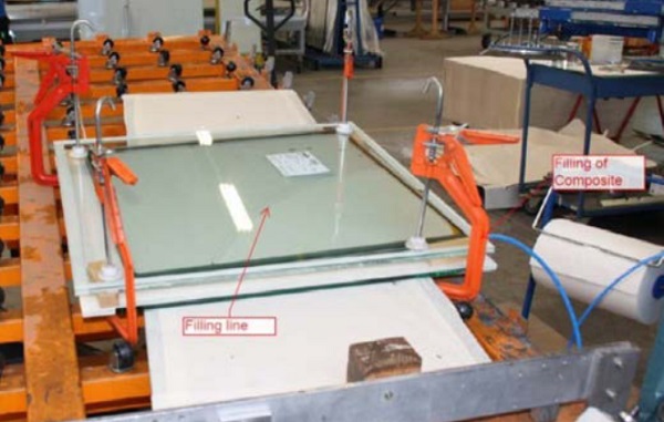
d) The individual glass lites were then laminated to create the interior and exterior glass sets that comprise each IGU panel. The laminations are performed by laying the glass panes flat and filling the GEWE resin in between the panes using a pumping mechanism. Once filled, the panes are clamped together and moved to a pre-curved jig. (Figure 7)
e) When the panels are brought over to the jig, they are clamped into a formed mold of the required project curvature. The resin then cures in the curved geometry. (Figure 8)
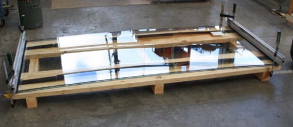
f) The laminating and curving process is completed for both the interior and exterior sets of the IGU
g) The both the interior and exterior laminates lites were assembled into the IGU complete with Argon fill, Edgetech Super Spacer Triseal, and stainless-steel bushings embedded within the secondary seal that is setback for the toggle connections.
4.2.Mockups
To ensure the achievement of waterproofing, structural performance, and aesthetic quality, the Architect, SGH, and Roschmann went through a progressive series of mockups for the Owner’s benefit. In the first phase of mockups a one-foot square panel assembly (straight) was made. In addition, samples of the toggle connection, wing plate, stainless steel shoe, and bottom of glass fin pin connection were all made available to the Architect and Owner for review and comment. After incorporating these initial comments, a three foot by three-foot curved glass IGU, complete with low-e coating, was fabricated and shipped to the project site. Once again, the Owner and Architect reviewed the mock-up and made comments and suggestions on the aesthetics. They also used this piece to formulate the frit pattern.
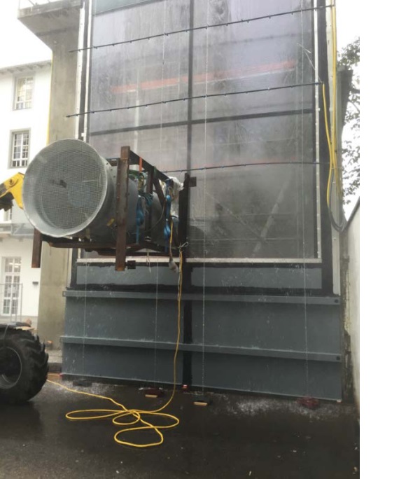
Finally, a full-size mockup of two vertical bays of the curved glass IGU and fin wall configuration was constructed at a testing lab in Austria.
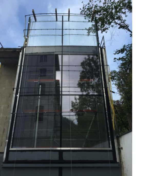
The full-size mockup was constructed on the front of a pressurized air chamber with spray racks at multiple elevations in front (exterior) of the wall. The following is the testing program that the full-size mockup was put through:
a) Preload at 50% of inward design pressure.
b) Static Pressure Air Penetration Resistance (ASTM E283)
c) Static Pressure Water Penetration Resistance (ASTM E331)
d) Dynamic Water Infiltration Test (AAMA 501.1 or EN 13050)
e) Structural Wind /Water test (ASTM E330 using NAFS/CAN/CSA A440 supplement)
f) Repeat b & 3c
g) Interstory Drift Test (AAMA 501.4 using 10 cycles)
h) Repeat b, c, & d.
In addition to the water and structural performance testing, the Owner and Architect surveyed the mockup for general aesthetic quality and visual imperfections. The mockup panel curve met the high expectations of the design team, with one slight modification required to the tangent ends, which tended to flatten. The Owner and Architect also inspected the mockup for deficiencies from the specified tolerances. The Architect found the crispness of the optical properties of the glass to be satisfactory. However, the horizontal frit lines did not line up from panel to panel in the mockup, and this would be successfully corrected in the final wall design.
4.3.Field Tolerances and Existing Conditions
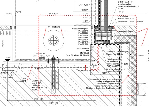
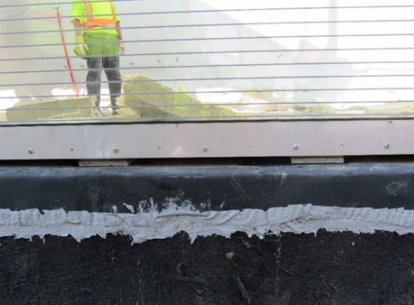
Pre-installation site surveys identified a 40mm plan offset in the anticipated wall location, in addition to variability in the concrete curb elevation. The specialty glass contractor coordinated the existing conditions with their installer (F&L Contracting and Consulting) to update the glass installation drawings to include the as-built elevation, measured tolerances, and required field adjustments. Installation drawings specified galvanized steel shims for installation at the glass panel sill and jambs. These were modified locally in the field according to field conditions. The site surveys and coordination efforts resulted in a successful installation with minimal delays due to unforeseen conditions.
5.Conclusion
The 160 East Elgin curving glass fin wall was initially inspired to develop a modern one-of-a-kind grand entryway that would match the high-end retail upgrade taking place on the interior of the building. In the evening, the entryway glows like a clear jewelry box providing an extra element of comfort and security to passersby on the sidewalk in front of the building. The ease at which the multi-layered glass panels and fins came together during fabrication was extra-ordinary, and can be attributed to the dedication of the design and construction team working together to make every detail meet its precise design purpose. In order to design, manufacture, test, and build such a highly accurate and transparent façade, the team utilized design codes from three different countries (Canada, Eurocode, and United States). The design and the construction team showed that such responsible engineering and coordination can be performed to a high level of accuracy and beauty, and completed this transparent project ‘ahead of the curve’.
Acknowledgements
Erik Farrington of Simpson Gumpertz & Heger for his contribution of reviewing this paper.
TriPyramid Structures Inc. for their help during the design phase of this project.
References
[1] Rendering courtesy of Petroff Partnership Architects.
ASTM E283: Standard Test Method for Determining Rate of Air Leakage Through Exterior Windows, Curtain Walls, and Doors Under Specified Pressure Differences Across the Specimen.
ASTM E331: Standard Test Method for Water Penetration of Exterior Windows, Skylights, Doors, and Curtain Walls by Uniform Static Air Pressure Difference.
AAMA 501.1: Water Penetration Test of Façade and Window / Door Systems Under Dynamic Pressure.
EN 13050: Curtain Walling - Watertightness - Laboratory test under dynamic condition of air pressure and water spray. NAFS/CAN/CSA A440: Windows.


