First presented at GPD 2017
Abstract
Currently in Spain the buiding’s restoration is world of rehabilitation of office buildings is at boiling point. Many of these restorations are made to adapt the building to legislation and to implement improvements in energy efficiency, but also to give them a new exterior image. This new image intends to be present and with a technological design without great design performances.
In this new image, use of structural glass is a perfect idea because it involves a minimal intervention with little visual impact, and current and technological elements. This is the case of the new hall Torre Europa in Madrid that shows as a free dihedral glass composed of mullions 10 m high on which a horizontal beam glass stabilizes the assembly is arranged, and which transmits the loads the main building structure.
The enclosure is made with laminated glass full height and 3 m wide which are stabilized by metal inserts to the mullions themselves, having revolving doors of access 5.50 m high. At the top as closing a skylight glass composed of 12 m long x 1.50 m wide is available. The project is owned by INFINORSA, and was conducted by the British architects RTKL with the Spanish study LKS. The facade has been consulting by ENAR and the project has been awarded for construction Bellapart.
Introduction
In Madrid North´s area, there is an area called AZCA, created in the 70’s of last century, where the financial center of the city is located. In this area, many of Madrid’s office buildings have been built since then. Nowadays, other bussines areas have been built, but this area is still the most valued and emblematic for this type of office, where are among other buildings like the Picasso Tower of Yamsaki and the BBVA Tower of Sáinz de Oiza.
The existing buildings in this area date from the same period between the 70s and 80s of the last century, and therefore these buildings need to carry out an update, in terms of benefits, regulations and image. This is the case of the Torre Europa Building.
Torre Europa is an emblematic building of this area of Madrid, located at the corner of the AZCA complex right in front of the Santiago Bernabeu stadium, with the facade in thePaseo de la Castellana. The building is a tower of 121 m of height built by the architect Miguel Oriol and Ybarra between years 1975 and 1985, property at present of the company Infinorsa.
The property has decided to make a complete rehabilitation of the building, including interior works, changing the air conditioning systems and eliminating the interior fancoils so that the glass is liberated from floor to ceiling, and also on the outside to give the building a new image more technological and current, according to the new times. For this reason, Infinorsa has counted with the team of English architects RTKL, along with the collaboration of the Spanish study LKS.
General description of the refurbishment
The current building has a spiral-shaped plant with a central core in which are the vertical communication and the general services, leaving the rest of the plant without other elements. The structural system proposed also contributes to this idea, since it has no intermediate pillars inside the office, the structural elements being centered in the central core and in the perimeter, outside the building. The pillars are prefabricated elements of Steel reinforced concrete. The pillars award a very characteristic image to the building in Madrid.
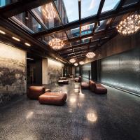
In the lower part an Access hall is situated tangent to the building, as an element added to the own building. This vestibule consists of a fully glazed element with vaulted elements and glass roof, made with an aluminum curtain wall system over steel structure. The exterior glasses are very darks with very little transparency, giving the building an old image that is inconsistent with the new Actual trends. The facade proposal made by the architecture study, RTKL, focuses on two main actions:
- Access update. The absolute remodeling of the acces hall is proposed, incorporating in addition an upper canopy of metallic structure that will be situated in the outside perimeter of the building.
- Pillar cladding. It is planned to update the building’s image by placing a textured stainless steel exterior over the prefabricated concrete pillars and the emergency staircase of the building.
In this article we will focus on the upgrade of the entrance hall of the building.
Description of the design
The refurbishment of Hall access involves the complete demolition of existing access for the construction of a new lobby with greater transparency and a more current and technological aspect. To get this new image, the architect choose a solution in structural glass, without other structure.
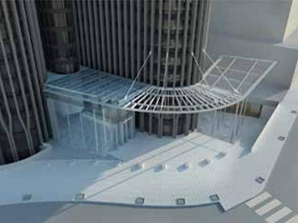
The access is made under a canopy of metallic structure that unifies the lower area of the main facade of the building, this canopy is supported in an area supported by pillars on the ground floor, while in another area there are hanged on the building to free the bottom zone from pillars.
The entrance hall is situated in the area closest to the building and it is attached to it to allow its enclosure as shows figure 1. The hall is closed at the top by a skylight that is supported on the metal structure of the canopy, and on its vertical facades by structural glass enclosures supported on the ground floor slab, independently.

The access is located in the north façade of the hall with two revolving doors of great dimensions that are included in the own facade.
At the bottom of the east facade, to the area of Paseo de la Castellana, there will be a sheet of water inside and outside the building that will allow the reflection of the building itself and the facade itself, dematerializing the support of the same.
In the transition with the existing building, and between the vertical facades and the upper skylight, ventilation louvres are introduced in case of fire to guarantee the evacuation of smoke from the hall because it is an escape way.
This zone of louvres is set back from the rest of the façades, so that the facades will be more exposed to the exterior, simulating a perfect glass cube, vertical facades and horizontal enclosure. The vertical glass is 10 m high below the upper roof of the canopy, which rises 1.50 m above, leaving in the middle the zone of louvres. The façade will have a dimension of approximately 11.00 m wide by 10.00 m high, divided into 3,00 m wide glass with corner glass of approximately 1.20 m.
The revolving access doors are integrated into the exterior facades, ie in the area of the glass cube, with a height of 5.50 m and a diameter of 3.00 m, with two side doors that will allow the evacuation of the building.
Structural Behaviour
The proposed structural beahuvior for access aims to separate the movements of the building and the canopy from the movements of the ground floor and access, to avoid possible differential movements between the two elements. In this way, the vertical enclosure of the access must be self-supporting and stable, transmitting the reactions to the ground floor and punctually to the building but without assuming the movements of it.
The upper part of the vestibule, that is to say the cover and the zone of louvres will depend structurally of the canopy, and therefore of the building, whereas the zone of the facades will depend on the slab of ground floor, taking in The strip of louvres the necessary expansion joint between both systems.
Roof Area
The roof area must support both wind stresses that collects the façade of the main building and throws towards the bottom and snow loads and maintenance overloads.
The roof is supported on a framework of lacquered steel beams, as a continuation of the outer canopy. The framework is composed of two main longitudinal beams parallel to the main facade of the building, on which transverse beams are arranged every 3,00 m approximately. The main beams are supported on pillars on the ground floor of the building and on the first floor slabs of the Tower itself.
A structure of glass beams is located at the top of each piece of steel beams on the upper part of the beams is provided every 1.50 m, which always is supported on the longitudinal beams, whether or not they coincide with the steel cross beams of the main structure. These beams have a span between supports variable of approximately 7.00 m, and with variable cantiléver from 1.50 to 2.00 m in length, with a maximum dimension of beams of 12.00 m on its side longer.
The beams have trapezoidal shape to give slope to the skylight and allow the water to be evacuated, so that the lower part is horizontal coincident with the main metal structure of the canopy and the top have the necessary inclination.
The anchors will allow the expansion and movement of the beams, without constraints, avoiding the vertical displacement in both pressure and suction, and will have elements of stiffening to avoid the movements perpendicular to the beam itself to achieve the general bracing of the skylight.
Over the glass beams will be placed the glasses of horizontal roof, which will be double glazing that will work supported on the previous ones.
The skylight extends outwards, outside the vertical walls, with a canopy over the access area. In this area the structural solution is the same as in the interior zone, but a cantilevered glass will be provided from the last perpendicular beam, being continuous with the previous glass.
From the metal structure of the upper part of the canopy a light steel structure is lifted to support the area of exutorios, which also hangs from the upper part.
Lower Cube area
The area of the cube must support wind loads in the vertical walls, in addition to the horizontal live loads.
In this area structural glass is used, all the facades and the horizontal trim element will be made of glass without any other type of main structure.
The lower part consists of a trihedron composed of the two vertical facades, with the upper horizontal element, which is supported directly on the lower floor of the ground floor. The vertical walls have vertical stiffening glass fins that also support the horizontal stresses of glass located in the joints between glasses every 3.00 m.
Both vertical faces and glass fins are embedded in the lower part, while in the upper part they are stabilized together by a horizontal “L” shaped beam that joins and stiffens both square facades, forming the self-supporting trihedron. All the set that stabilized to the main building by two points in the corner of the trihedron, that transfer the efforts to the main building.
The horizontal beam is attached to both the vertical glass fins and the vertical glass, and in the corner between both facades. At the two ends of the cube a larger dimension glass fin is arranged as a closure of the assembly that reaches the inside part of the louvres. This beam has a steel element in its interior that gives it vertical inertia to avoid the vertical deformation of the horizontal element, as well as to achieve the transfer of shear in the area of attachment and in case of breakage of any of the sections.
These points of fixing to the building are made up with a cantilevered beam to support the horizontal stresses, with a pillar supporting the weight of the beam itself, and which helps to support the vertical enclosure of louvres side walls.
In the area of the doors, in addition to the supporting structure of glass are added stainless steel frames to support the upper windows and the transmission of stress through the doors’ holes.
Calculation Made
The calculation justification for the different elements is done from different scenarios:
- Overall operating model
- Timely model of the elements separately
- Detail model of fastening elements.
In these scenarios it is necessary to take into account the hypothesis of the breakage of some of the elements to avoid the collapse of the structure, to take into account these criteria in the constructive solution to be developed.
The overall model is made by a bar system, verifying that both tensions and compressions are below the admissible values of the glass (according to pr UNE EN 16612), and the overall deformations of the assembly are checked to check the structural viability. The calculation of the main elements is done by a program of finite elements specialized in glass to be able to guarantee the union between the different materials.
The detail models are also made with a finite element program to guarantee the minimum dimensions of the elements to be realized. This third part will be developed later by the contractor hired to carry out the work, in this case Bellapart, which will also provide possible solutions to the problems encountered.
Proposed construction solution Superior Zone. Skylight
The area of the upper skylight is solved with laminated glass beams 10.10.10 mm with a stainless steel plate glued on its upper part on which a standard skylight head with its EPDM rubbers is arranged which will guarantee the operation and the sealing of the system.
A double continuous glazing throughout its length is made up of an outer tempered glass of 10 mm with greater resistance to withstand hail or falling elements and an inner laminated safety glass 6 + 6 mm fall, all of them are low iron to avoid the green color of the glasses. The fixing of the glasses is done by means of a stainless steel outer cover. The evacuation of water is done towards the area of the building, where a continuous gutter is arranged which coordinates with the drainage of the building itself.
In the lower part of the skylight there is a strip of louvres that Works in case of fire. These louvres have an approximately 1,50 m in height, coinciding with the actual cutting of the roof. The louvres will be of pivoting glass slats and will have motorization hidden in the vertical uprights of fixation. The louvres will be laminated glass 5 + 5 mm without elements between joints between louvres to guarantee a greater transparency of the enclosure.
Bottom area. Glass Cube
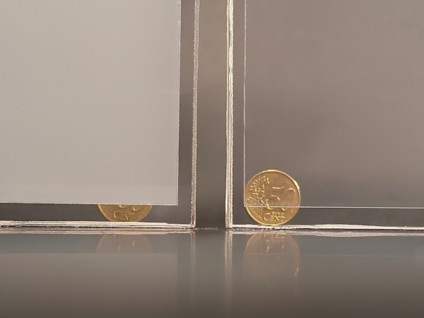
The vertical glass is made with 12 + 12 + 12 mm monolithic laminated glass laminated with SGP to provide the assembly with greater stiffness and greater post-break safety. These glasses are embedded in the lower part with stainless steel anchors, which must also be compatible with the waterproofing trim and bottom water sheet.

The inner glass fins will also be embedded in their lower part on anchors of galvanized steel with three-dimensional regulation as shows figure 2. The fixing between the glass fins and the anchors is made by stainless steel screws with inner bush. To guarantee the position of the holes, a resin with characteristics of strength and hardness higher than the glass itself will be used.
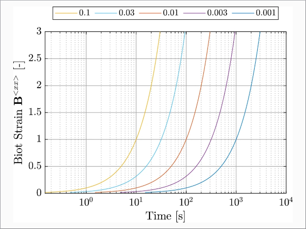
The connection between the inner vertical glass vertical and the vertical glass is done by Titanium elements laminated with the glass itself thanks to the use of the SGP. The connection is made by inner clips that are introduced through the joint between glasses as shows the figure 3.

In the corner glasses also a connection between the glass of the enclosure and the lateral glass fin with screwed fasteners is made, in addition to using structural silicone glue strings.

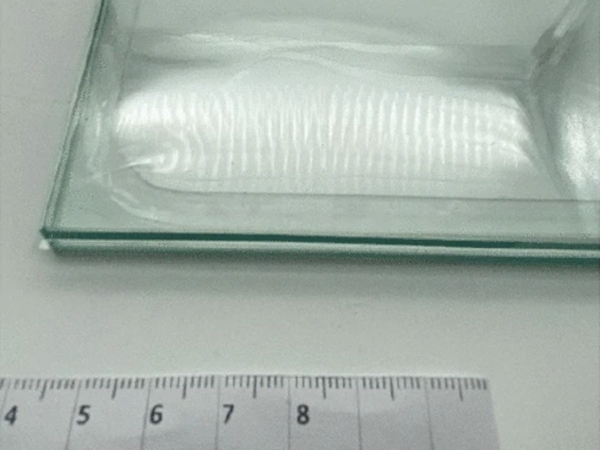
The upper joint of the glass fins with the horizontal top glass beam is also made with titanium inserts on both sides and then with countersunk screws, all without external elements to guarantee the watertightness of the assembly in the horizontal part as shows figure 4.
The upper horizontal element will have a horizontal continuity profile of stainless steel that is screwed to the different glasses to achieve the transfer of the efforts between them, as well as stabilizing element with the own building. This element will be able to support the tensions created by this beam in case of breakage of some section of the beam, as well as connecting element for the replacement of glasses separately. On the other hand, this element serves as flexible connection between the lower part of the hub and the top cover.
In the access area, the doors of the building are arranged, which will also be fixed on the inner structural glass fins, supported on the stainless steel frames in the same way, through the joints between glass and elements.
Solution to build. Problems of refurbishment
For the execution of the project has been contracted the company facade Bellapart, which has begun the development of its own construction project as an evolution of the architectural project delivered. The project carried out by Bellapart respects the design and structural criteria set out in the submitted project, but makes a series of changes to improve its implementation and to adapt to its philosophy of work.
Additionally, in the beginning of the work, since it is a refurbishment, it has been discovered that there are elements in the building that do not correspond to the elements expected in the architectural project, such as that the ground floor slab does not have the Resistance required and the execution of reinforcements is necessary
For all this, a series of changes have been made in the project, approved by all parties for its correct execution.
Conclusions
As main conclusions after the realization of the project of rehabilitation with structural glass we can obtain the following conclusions:
- Structural glass can be an important design element in the rehabilitation, since it throws a novel and technological image, according to the required changes of image.
- The transparency and low presence of structural glass elements as a restoration enclosure, lead to an easy coexistence between them and existing buildings.
- Rehabilitation works have a high degree of uncertainty that can change the criteria at the beginning of the work.
Acknowledgements
INFINORSA. Owner
RTKL & LKS. Architect Office
BOVIS. Project Manager
BELLAPART. Contractor


