This paper was first presented at GPD 2023.
Link to the full GPD 2023 conference book: https://www.gpd.fi/GPD2023_proceedings_book/

Author: Dirk Schulte
Abstract
Existing commercial buildings in modern metros are deemed to change faces with increased transparency if they want to welcome public well-being and turn into quality enhanced environments. The CME Center in Chicago was one of those places built in the 1980s with dark lobbies and mazelike retail spaces lacking access to daylight while creating uninspiring experiences to tenants and visitors. The new glassy podium enclosure opens the space with super transparent 24 foot tall and curvy façade lines, moving outward to flow around the building, providing serpentine circulation between lobby and adjacent streets. The all-glass enclosure floods the lobby with natural light, minimizing materials, engineered with a sophisticated modular geometry.
Oversized temper-bent, laminated glass was used to overcome the challenge of dematerializing the podium wall. Minimizing optical distortions on temper-bent glass surfaces was managed by implementing a custom quality control process during glass fabrication by measuring surface flatness towards tolerance-based benchmark programs setting new standards for practical quality control of temper-bent glass. Shipping and installation of jumbo glass panels followed a sophisticated procedure of efficiently reusing elements and equipment contributing to reduce the carbon footprint of the renovation process. A guideline for successfully retrofitting existing buildings with engineered glass.
Introduction
Before introducing the case study of the CME Center lobby façade renovation, the thesis of using glass as a material in modern architecture to emphasize on value, comfort and inhabitant quality shall be combined with the basics of design and function of the architecture. While considering commercially used buildings, a transparent glass storefront can attract people in several ways:
- Visual Appeal: A well-designed glass storefront can be visually appealing, drawing the attention of the passersby. The use of clean lines, striking colors, and interesting architectural features can create an eye-catching display that entices people to take a closer look while feeling comfortable and invited to enter the building.
- Window Displays: A glass storefront can serve as a canvas for creative and engaging window displays. Retailers can use their storefront windows to showcase their products, highlight sales or promotions, and tell a story through visual merchandising.
- Natural Light: The use of glass in a storefront allows natural light to filter into the space, creating an inviting and welcoming atmosphere. This can be especially attractive in urban areas where natural light may be limited.
- Transparency: A glass storefront can convey a sense of transparency and openness, making potential customers feel more comfortable and confident in their decision to enter the building.
- Branding: A well-designed glass storefront can also serve as a branding tool, allowing businesses to display their logos on or through and other branding elements in a prominent and visible way.
Overall, a transparent glass storefront can be an effective way to attract people to a business by creating an inviting and visually appealing space; especially, if the lobby space of the building shall further be accessible to the public for creative collaboration and use to showcase the products or services offered.
The Project: The Chicago Mercantile Exchange (CME) Center is a Class-A office complex that is made up of two 40- story towers which are connected by a 10- story center structure, occupying a full city block around Wacker Drive between Madison and Monroe Streets in Chicago, Illinois, USA. The complex was completed in 1987. Fujikawa Johnson Architects designed the buildings, which are the 87th tallest in Chicago and one of the City’s most prestigious office buildings nowadays. "The Merc" is also known by its address, 10 & 30 South Wacker, Chicago, IL, being prominently nestled in Chicago’s prime business district.
In 2016, Tishman Speyer Properties, as the building owner, appointed Chicago based architectural firm Krueck Sexton Partners to develop an architectural concept to redevelop the building lobby space transforming the building’s podium into a warm and welcoming environment attractive to the surrounding public.
Architectural Design
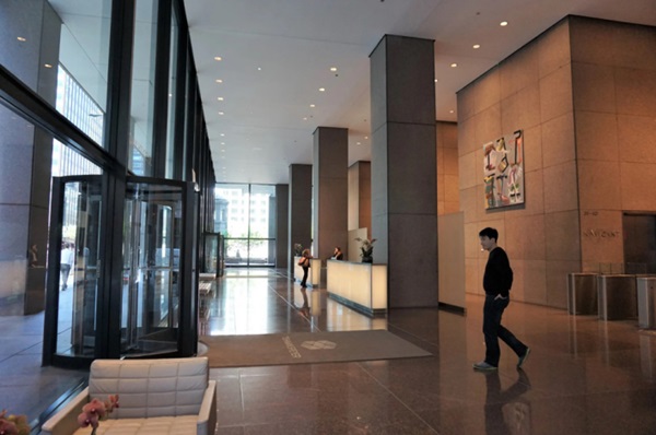
Before: Over the course of every workday, around 10,000 people enter and exit the CME Center in Chicago. For years, this experience entailed using one of 18 separate entrances leading into a dark ground floor area with shaded corners and pathways within the grand lobby of the buildings. The elevators' route was studded with planters, bike racks, slopes, ramps, and turnstiles. Reaching certain destinations required leaving and re-entering the premises.
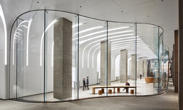
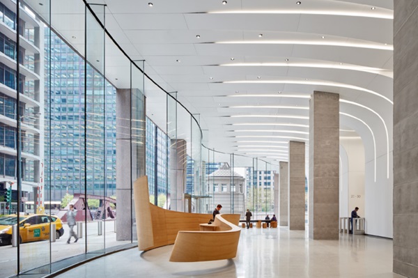
Intension: Unraveling the knot of unpleasant pathways with insufficient lighting depended on developing a new internal geometry. Studying the movement of people in, out, and through the center facilitated creating an intuitive, graceful experience. The new façade line should open up the lobby by establishing a curving move outward and inward to flow around the building cores, providing serpentine circulation between the buildings and a geometry that encourages a greater connection to the street. While using an allglass façade design, a sophisticated system of modular implemented geometries should be hidden behind simple and minimal materials developed and composed in an engineering feat.
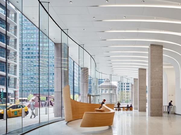
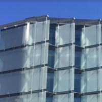
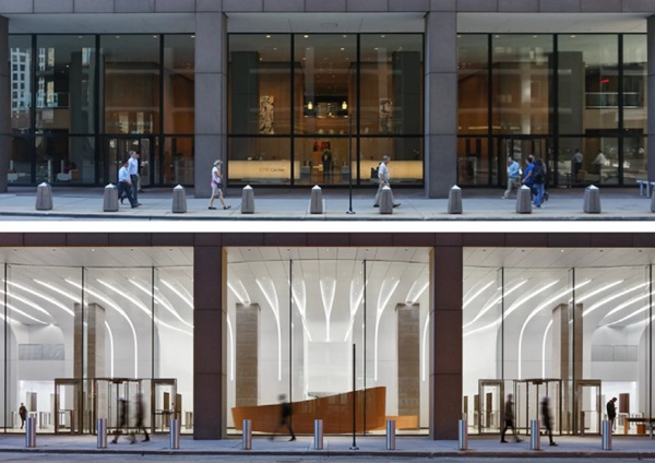
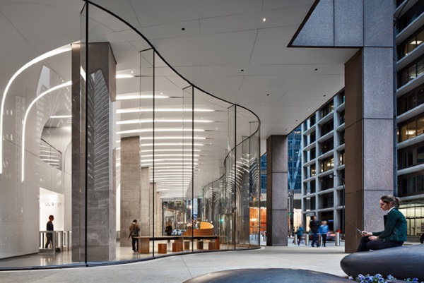
After: Walls made of glass to let the life in! The redeveloped CME Center lobby is defined by a striking, wavelike 24’ tall glass façade. The glass encircles the building, brightening entryways and street-level retail, and bringing in the sights of the city.
Design Assist & Material Selection
A Design Assist was awarded to turn the architectural vision into a constructable reality, considering aesthetics, budget, schedule, technical feasibility, expected quality and material selection. Right from the beginning of this process, it was important to set the criteria for establishing a consistent and target orientated, efficient workflow. The below outlines criteria chosen by the architectural design team:
- Material Selection: analyze the properties of different types of glass to determine which one is most suitable for this particular application. Factors such as strength, transparency, thermal properties, optical qualities and chemical resistance were considered for the selection process.
- Design and Modeling: modeling techniques have been used to create detailed interface designs of glass components and surrounding structure. This included specifying dimensions, tolerances, and surface finishes, ensuring that the final product meets the required specifications.
- Fabrication Techniques: Development, selection and optimization of the fabrication processes for glass, including raw glass selection, laminating, and bending.
- Quality Control: Establishment of a custom quality control procedure and inspection technique based on pre-approved benchmark glass to verify the integrity and performance of the fabricated project glass product. This involved testing for strength, transparency, optical properties, and adherence to specified tolerances primarily being developed for each curvature.
- Manufacturing Equipment: Contribution of the glass fabricator to the design and development processes while providing input from the fabrication floor, ensuring that the available equipment improves productivity, and enhances the overall fabrication process.
- Process Optimization: Analyzing and benchmarking the design with the fabrication processes to improve efficiency, reduce costs, and enhance the quality of fabricated glass products.
- Research and Development: Exploration of glass fabrication techniques, materials, and detail applications to push the boundaries of glass fabrication to close the gap between architectural intention and practical reality.
The Design Assist process included various rounds of engineering and material presentation. Initially, various types of lowiron glass substrates were presented and compared to ensure a selection of optical quality matching with the owner’s budget and the project teams supply chain. Furthermore, the award of the glass fabricator was an integral part of the Design Assist process and had to be pulled into an early project stage to allow for extensive design modifications in harmony with the available fabrication techniques.
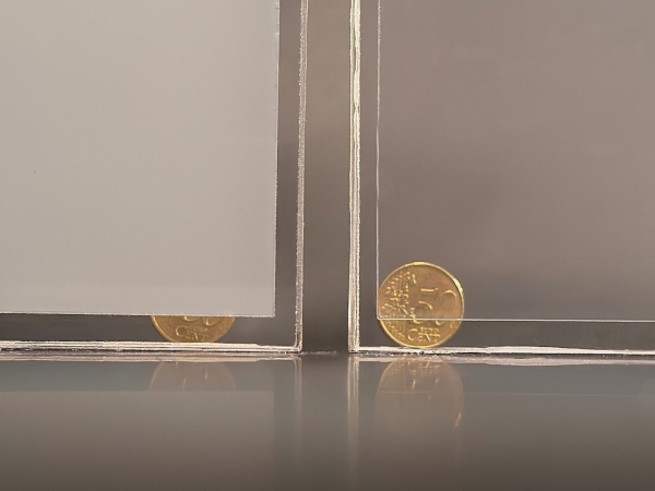
As thermal performance of the façade was a minor factor in this project, the design lead towards improving the transparency with a laminated glass composed of 2 x 3/8 inch (10.00mm) thick low-iron glass layers, laminated with a 1 x 1/16 inch (1.52mm) thick SentryGlas® interlayer. Supporting fins behind each vertical butt joint were formulated with 3 x 5/8 inch (15.00mm) thick low-iron glass and 2 x 1/16 inch (1.52mm) thick SentryGlas® interlayers.
Engineering follows Fabrication follows Engineering
The glass fabrication process and its technical capability was a crucial aspect of engineering the lobby façade, particularly under consideration of the full height between the floor and lobby ceiling, wavy line of the glass walls floor plan and incorporation of multiple entrance doors. The process of glass fabrication involves shaping, cutting, forming/bending, tempering, and finishing the glass product to meet the specific design and function, but also performance related requirements at the same time. The project engineering team played a significant role in developing and implementing various fabrication and control techniques in close coordination with the glass fabricator and his ability to modify the fabrication parameters for the glass during bending, tempering and laminating the oversized panels.
A key element solely determined by engineering was the technique of how Bending of the Glass was processed. While Hot-Bending was preferred by the architectural design team for the purpose of limiting optical distortions on exterior glass surfaces caused by surface imperfections such as production process introduced roller waves, several engineering driven criteria lead to a controlled TemperBending process. A few characters of both techniques are briefly summarized as below.
Hot-Bending (slumping) of architectural glass uses prefabricated molds, allowing the glass to adopt desired shapes under heat up to temperatures of 580–600 degrees C. Bending of the glass solely appears based on gravity. Advantages are (almost) limitless shapes such as 2D and 3D shapes within large and tight radii accompanied by minimal surface imperfections. Disadvantages are cost and energy extensive fabrication processes as well as glass being limited to annealed mechanical strength as tempering is not possible. Temper-Bending (online) of architectural glass uses industrial online operated furnaces to heat the glass up to its softening point, curving the glass with a mechanical operable mold to obtain the required shape and then quickly cool down the glass allowing its surface to trap a high compressive strength at the curved surface. Advantages of this technique are highstrength levels of heat-strengthened or fullytempered glass, an economical fabrication process and the ability to bend highperformance low-e coatings. Disadvantages are limited shapes and radii plus tempering introduced surface imperfections such as roller waves and local bows.
For the project, and after carefully analyzing the pros and cons of each fabrication process technology, the final decision was made towards using Temper-Bending over HotBending for reasons outlined as follows:
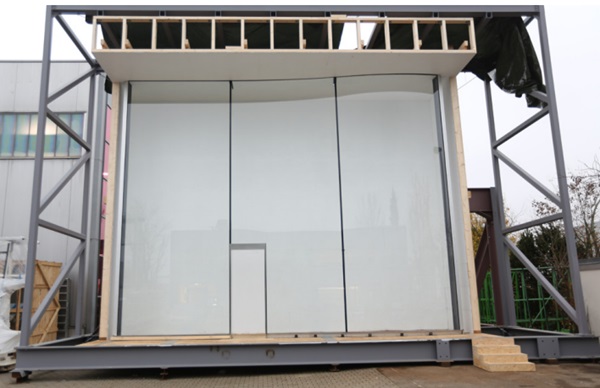
- Use of heat-strengthened glass in lieu of annealed glass to minimize the glass thickness for cost purposes; 24ft tall glass units are 4- sided supported, while being restrained within U-channels at top and bottom, long side edges are structurally bonded to supporting laminated glass fin edges located at the interior which allowed for an effective bonding surface limited to ½ inch (12.00mm), only.
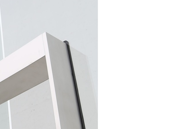
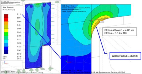
- Use of fully-tempered glass for full-size units incorporating entry doors. Those units were fabricated with a rectangular notch cut-out to accommodate the door frames, resulting into L- shape units with a 270- degree glass corner relaxed by a minimal radius to control the stresses introduced by fabrication, handling and design loads. This unit would have to be split into two units, if being made by HotBending, which was undesirable by the architectural design team.
The above process involved a close collaboration between the architect, owner, engineers and the glass fabricator striving to improve the efficiency, performance, and aesthetics of final glass product, enabling its use for this individual project application.
Quality Control Process
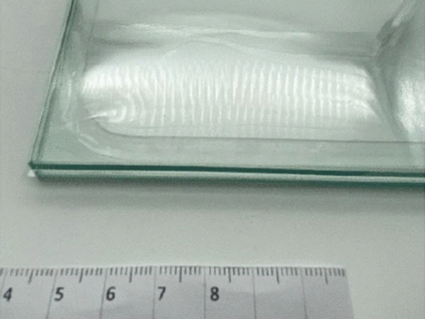
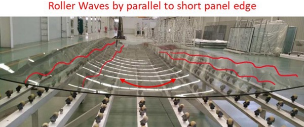
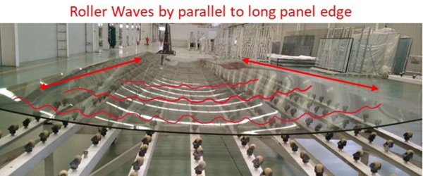
While general quality control procedures and measures were implemented into the material fabrication and execution process, special care had to be focused on the glass. Curved Temper-Bent glass, such like flat fully-tempered or heat-strengthened glass, moves on rollers through the online tempering chamber and cooling quench. Those rollers leave waves & local bows on the glass surface, typically running by parallel to the panels short edge (latitudinal). Temper Bent Glass in particular battles with another direction of waves by parallel to the long edge as the curving quench includes wheels in longitudinal orientation. Those local bows had to be considered, controlled & measured under a custom developed control program including limited tolerances agreed and approved by all parties. Predominant quality control measures were set as follows:
- Local and overall bows incl. edge dips
- Roller waves along short (latitudinal) and long (longitudinal) panel edges
- Curvature consistency and latitudinal radius tolerance
- Laminated edge offsets
- Uneven anisotropy clouds appearance by expressive rainbow or pattern coloring
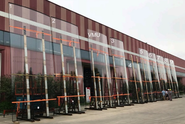
First, the team had to agree on a maximum level of acceptable tolerances. By having a transparent material such as glass being bent into various shapes with different angels of reflection, no code standard could be used to benchmark acceptable qualities. Therefore, the team agreed to fabricating full-size benchmark units based on varying machine parameter adjustments. Then benchmark units were inspected, and test measurements were taken in order to set a standard for the project production.
Another level of complication was introduced as no practical tools were available to measure the longitudinal waves over varying radii. Neither electronic scanning equipment was developed and available in the market to survey those imperfections nor standard tools such as roller-waver measuring gauges were able to measure waves along a convex and concave curved surface. For that reason, single measurements had to be taken by increments following a screen grid laid over each panel while having the unit being setup into an upright position on a rack and outside of the fabrication plant. The result of measures taken was then computed into a data base and analyzed based upon dimensional dependencies along the measuring lines on the glass surface.
The described complex process of roller wave evaluation & maintaining curvature consistency on Temper-Bent glass panels in latitudinal and longitudinal direction required multiple inspections within a tight fabrication schedule based on project individual quality control and assurance standards broken down into a commonly agreed process as: 1- Criteria Setup, 2- Measurement, 3- Analysis and 4- Approval/Release.
Construction Process
Shipping: Shipping of the 24 foot long, oversize and curved glass units was a complex process due to the fragility, shape and dimensions of the units. Considerations included an early development of various logistic concepts including, but not limited to:
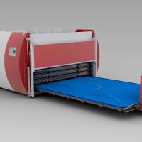
- Packaging and Crating: Proper packaging was crucial to protect the glass during transit. Each glass piece has been securely crated with suitable protective materials. Reinforced wooden crates have been used to provide additional protection and structural support. Crates were designed to accommodate the size and weight of the glass, with appropriate bracing to prevent movement.
- Freight Carrier Selection: A freight carrier experienced in handling delicate, and oversize glass has been selected early in the process. Expertise in handling glass is a key to avoid costly damages.
- Documentation and Labeling: To ensure a sequential installation of glass on the job site, properly labelled packages have been introduced. As it was difficult to open boxes on site due to space restrictions, an efficient installation process starts with crating the glass in the dedicated sequence.
- Handling and Off-Loading: Special care was taken when on-loading and off-loading the oversize crates and glass units off the crates.
- Tracking and Monitoring: One key element within the logistic chain was a custom tracking and monitoring process implemented between the glass fabricator and project management team. This allowed for continuously staying informed about location and estimated arrival times, enabling to coordinate with the Site Management team and to ensure proper arrangements for unloading in time.
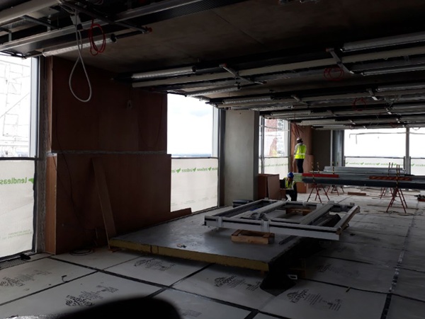
Installation: As for the installation of the 24-foot-tall glass units, the project team was facing a common challenge typical for a retrofit renovation of lobby or storefront facades. The Lobby is setback from the exterior façade line, which creates great complication when it comes to the handling and installation of the large size units on site. Two options have been investigated and compared towards time, cost and risk:
- Installation with a Mobile Crane: setup from street or plaza level, particularly during off-hour times to avoid disturbance of the public traffic in and around the building, which kept being fully occupied during the renovation. Advantages are that the mobile crane may handle multiple glass units during one shift as being setup in a particular location cutting down time during arrival of the glass to site. Disadvantages are the costly rent for large mobile crane equipment, custom glass suction cups with counter-weight, and operating engineers hired for off-hour work as well as potential fees for lane closures and police watch.
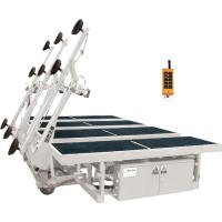
- Installation with a Building Integrated Monorail System (BIMS): installing glass using a monorail system can be an efficient and safe method, especially for large or heavy glass panels. As a general rule of thumb for installing glass with a monorail, the engineering effort becomes extensive as a custom system must be designed and permitted for the individual project. This requires an equipment provider and Professional Engineer (P.E.) to verify the custom solution to code and standard. Another disadvantage may be the longer lead time and duration on-site required to manipulate the glass units to their dedicated location as the drive becomes longer every time a glass is set and installed. On the other hand, a monorail method offers more flexibility and can be utilized and operated where space is limited within a built environment and throughout all hours of the day, consequently saving cost if being designed with under consideration of an optimized installation sequence.
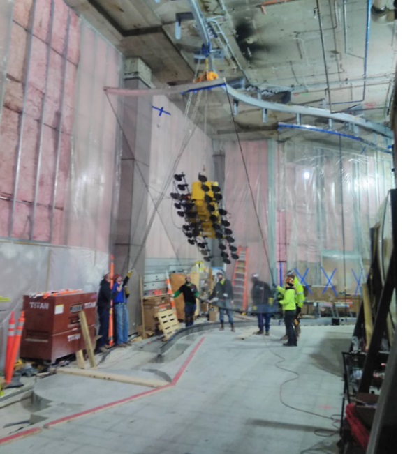
As the soffit above the lobby space at the CME Center was undergoing a massive renovation process too, and through a collaborative approach of coordination between the Field Management team and the owner, the installation method for the oversize glass has been developed under a utilizing monorail system (BIMS) fixed and installed into the interior ceiling to manipulate the glass from a secured loading (pick-) location to its dedicated location of installation. The monorail system was designed to be utilized for installation, potential replacement and cleaning purposes throughout the construction phase as well as retains embedded in the ceiling for future use, making it a permanent addition to the buildings facility operation.
Conclusion & Guideline
Modern technologies in fabricating architectural glass open a wide spectrum of applications for retrofitting existing real estate within the built environment of a dense metro. Based upon this case study which reflects the process of design, engineering, fabrication, and execution of the new all-glass lobby storefront for the prestigious CME Center in Chicago, a close collaboration between all parties incl. glass fabricator and façade contractor was identified as key to success.
A guideline scheme is to establish a clearly communicated and commonly agreed process, starting with the implementation of a target driven Design Assist goals within an early stage of the project. Criteria are to be set and to be followed by parallel to allow room for optimization of design in compliance with the expectation of owners and architects. This allows to evaluate options under different criteria, proceeding with purpose driven selections of materials and design interfaces.
While following an engineering focused glass selection process, a new method of controlling optical surface quality of Temper-Bent glass was developed, conducted, and successfully established to assure that project glass fabrication meets the standards accepted by the owner and architectural design team. This quality control method includes measuring and analyzing longitudinal roller waves on 2- dimensional Temper-Bent glass units within varying curvature radii.
The CME Center’s new lobby façade has been completed in 2020. The architectural design vision for the lobby was to build brighter spaces that encourage collaboration with coworkers and clients, being an open invitation to the public at the same time: to find your favorite place and take your rest, in comfort.
References
[1] Wikipedia, https://en.wikipedia.org/wiki/Chicago_Mercantile_Exchange_Center
[2] Krueck Sexton Partners, https://ks.partners/projects/cme-center-chicago-mercantile-exchange/
[3] Tishman Speyer; CME Center; https://www.cmecenter.com/lobby/
[4] Roschmann Group, project documentation
[5] Photos Hall & Merrick