Authors: Julian Hänig & Bernhard Weller
Source: Glass Structures & Engineering | https://doi.org/10.1007/s40940-021-00153-x
Abstract
Composites are being increasingly used for industrial applications and combine the advantageous properties of two or more constituents. The urge to reduce material to a minimum and the trend towards lightweight glass structures require further developments in high performance and fully transparent composite structures for the building industry. Novel innovative glass–plastic-composite panels combining a lightweight polymer polymethylmethacrylate (PMMA) interlayer core and cover layers of thin glass are currently under development. The panels exhibit high structural load-bearing performance, are durable and fully transparent with a low self-weight.
These properties make the composite panels suitable for slender and lightweight glass constructions and reveal new design possibilities for the building industry. However, the material properties of the modified PMMA polymer interlayer core for precise design considerations are lacking. Furthermore, the material behaviour of thermoplastic polymers changes over time, ages due to environmental influences and is temperature-dependent. This significantly affects the composite load-bearing behaviour and defines the limits of application for the composite panels in the building industry.
In order to facilitate during the development process and to build a design basis for the composite panels, material model parameters and simulation methods are required. Hence, an extensive test programme was conducted to investigate the material properties of the PMMA interlayer core by means of dynamic mechanical thermal analysis as well as uniaxial tensile and creep tests. The dataset and subsequent implementation into finite element software allowed for realistic simulations of the glass–plastic-composite panels and an extension of experimental results. Numerical simulations were performed with the commercial finite element programme ANSYS Workbench 19.3.
Additionally, four-point bending tests were performed on composite test specimens with a different build-up and conventional glass panels to validate the material model and finite element simulations. These investigations and adopted material properties formed the basis for a numerical parametric study to evaluate the influence of stiffness, the load-bearing and lightweight performance in different build-ups. All the results are evaluated in detail and discussed in comparison with conventional monolithic and laminated glass panels. The dataset and material model parameters can be applied to further developments and design of lightweight glass–plastic-composite panels for structural applications in the building industry.
Introduction

Composites combine the benefits of two or more materials and exhibit improved mechanical properties over conventional materials. In different industries, such as automotive and aerospace, lightweight, strong, stiff and durable composite materials are frequently used and developing at a high rate. Similarly, the glass industry is searching for novel lightweight glass composites with high structural performance to realise slender structures with maximum transparency (Nehring and Siebert 2018; Neugebauer et al. 2018; Ribeiro Silveira et al. 2018; Weimar and López 2018).
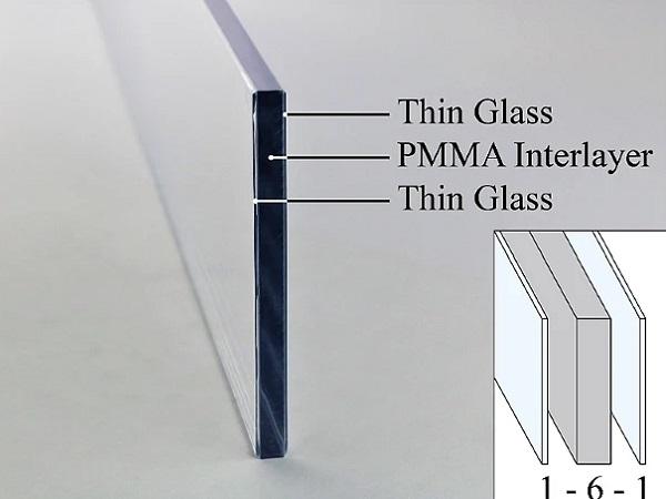
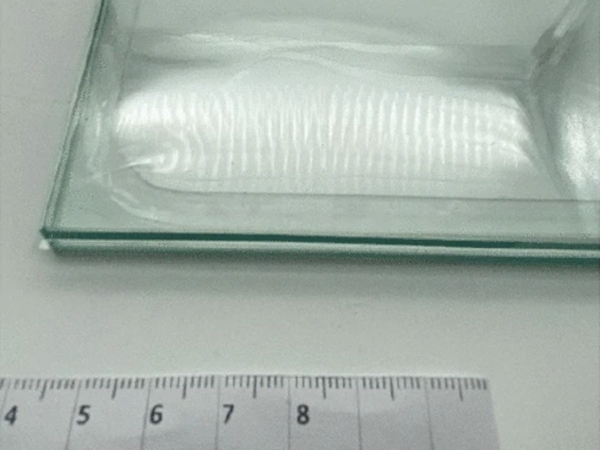
Glass–plastic-composite panels, called NEEROGLAS®, combine lightweight polymethylmethacrylate (PMMA), also known as acrylic glass, as plastic interlayer core and thin glass as protective cover layers in a fully bonded transparent sandwich assembly (see Fig. 1a). A casting manufacturing process bonds the polymer interlayer core to the glass through radical polymerisation without the use of adhesives or interlayer films. Covalent bonds at the glass interface result in strong adhesion and shear coupling between the layers. Additional edge processing provides high glossy finish, like the conventional glass edge polishing.
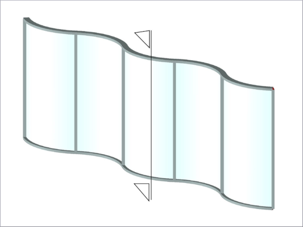
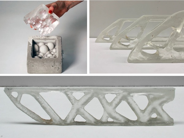
The promising material combination and composite load-bearing performance pushes the boundaries for novel innovative lightweight and transparent glass structures. Mechanical milling, drilling and processing of the polymer interlayer core enables novel discretely bonded and mechanically integrated connection joints (see Fig. 1b). A high structural performance combined with low self-weight provides novel design possibilities.
Glass–plastic-composite panels can be manufactured with a total interlayer core thickness of up to 20 mm with all types of cuttable glass—preferably 0.5 mm to 3 mm in thickness (Neeb 2017). Hence, combinations with annealed (ANG) and chemically strengthened glass (CSG) are possible. CSG would enable higher impact resistance, improved flexural strength as well as higher scratch resistance, however, at increased costs compared to ANG (Karlsson et al. 2010).
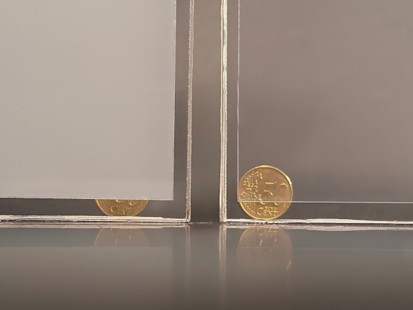
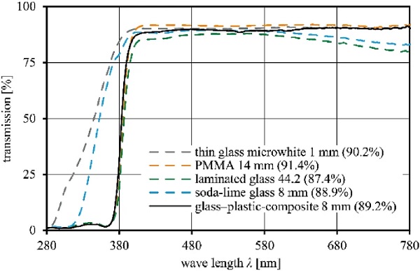
The light transmittance of glass mainly dependents on the glass composition, supplier and thickness. Figure 2 compares the light transmission in visible light range according to (DIN EN 410:2011-04 2011) of the novel glass–plastic composite build-up and its individual layers to conventional glass with total thicknesses of 8 mm. The light transmission of the glass–plastic composite (containing UV absorbers in PMMA) with 1 mm thin glass cover layers is 89.2%, marginally higher than the light transmission of conventional soda-lime glass (88.9%).
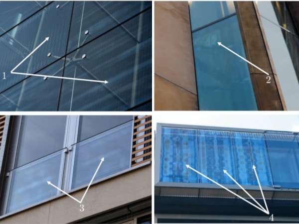
Within the polymerisation process of the composite panels, transparency, UV-transmittance, adhesion, and mechanical parameters of the PMMA interlayer core can be modified by adjusting the chemical composition and fillers. Multi-coloured panels can be produces with colour-filled interlayer cores and even infills, such as LEDs, fabrics, metal grids and solar panels can be integrated in the design.
Conventional laminated glass for building industry application has been extensively investigated. The mechanical properties of glass are isotropic linear-elastic and very well known. The interlayer properties have been also widely studied in last decades, as described in the review of (Martín et al. 2020). A wide range of material investigations and models for standard polyvinyl butyral (PVB) (Andreozzi et al. 2014; Botz et al. 2019; Sobek et al. 2000), ethylene-vinyl acetate EVA (Hána et al. 2019; Schuster et al. 2018), polyurethane PU (Scherer et al. 2020), thermoplastic polyurethane TPU (Kuntsche 2015; Rühl 2017) and stiff PVB interlayers (Kuntsche 2015) are available for implementation in analytical calculations and numerical simulations.
The application of the novel glass–plastic-composites, as a lightweight substitute to conventional glass panels in the building industry, requires the knowledge of precise material properties of the PMMA interlayer core and detailed composite load-bearing behaviour. The mechanical properties such as strength, rigidity, ductility, temperature dependency and durability are highly important for the structural design. Various parameters, such as loading rate, temperature, environmental influences and manufacturing greatly affect the molecular characteristics and mechanical properties of thermoplastic polymeric materials.
It is particularly important to determine the PMMA’s glass transition temperature in order to ensure thermal stability of the PMMA in the temperature range defined by the final application of the composite. Dynamic mechanical thermal analysis and material testing evaluate the temperature-dependent material properties and define the effective application limits for the material. Furthermore, the understanding of the influence of durability and ageing on structural behaviour is a key requirement for the application in the building industry, particularly in façades with exposure to climate changes, high radiation and moisture.
Commercial PMMA product material properties have been extensively investigated with regards to their yield behaviour (Rühl et al. 2017; Zhang et al. 2016), creep (Arnold and White 1995; Crissman and McKenna 1987; Fernández et al. 2011), ageing (Martinez-Vega et al. 2002) and solvent stress crazing (Andrews and Levy 1974); laminated PMMA-TPU setups subjected to low velocity impact were investigated in (Rühl 2017) for automotive applications.
However, material composition variations with the addition of modifiers, such as adhesive promoters for achieving the adhesion to the glass surface, and the customised polymerisation process for glass–plastic-composite panels affect the material properties of the PMMA (Neeb 2017). Significant changes in performance are expected compared to industrially cast or extruded PMMA products. Furthermore, the exact PMMA interlayer core applied in the here explored composite panels has not been investigated regarding the specific building application requirements related to loading, temperature and durability.
At present, a comparative study of the structural load-bearing behaviour and lightweight aspects of the glass–plastic-composites versus conventional glass panels has not been performed. In order to enhance the understanding of the structural behaviour of glass–plastic-composite panels, the extensive experimental study presented in the first part of the paper investigates the temperature and load-dependent mechanical properties and the durability of the reference PMMA interlayer core material. Additional four-point bending tests examine the composite load-bearing behaviour in comparison with conventional glass panels. This gives a broad experimental basis for the evaluation of the composite material behaviour for the application in the building industry.
To reduce extensive testing and prototyping, calculation methods or computational models are essential for the development, structural optimisation and design. Therefore, in the second part of the paper numerical simulations and the use of suitable material models based on the experimental dataset provide further insights on the structural behaviour. Parametric studies investigate the influence of the PMMA interlayer core Young’s modulus on the composite stiffness and load-bearing behaviour across a wide range of glass–plastic-composite panel build-ups.
Furthermore, an assessment of glass–plastic-composites in comparison with conventional glass panels in terms of structural performance and lightness is provided. The paper combines a material study on the PMMA interlayer core and the glass–plastic-composites with numerical investigations for detailed investigations and extension of results. All results are evaluated and discussed in detail with consideration of the requirements in building applications. Based on the overall work, the final section summarises the results, draws conclusions and gives a short outlook for further research on the topic of glass–plastic-composite panels.
Study approach
This paper presents an extensive study following a bottom-up approach according to Fig. reff3. The experimental test program includes material investigations by means of dynamic mechanical thermal analysis (DMTA), uniaxial tensile tests (DIN EN ISO 527-2:2012-06 2012) and uniaxial creep tests (DIN EN ISO 899-1:2018-03 2018) at different temperatures, as well as artificial ageing on dumbbell test specimens (DIN EN ISO 3167:2014-11 2014) of the PMMA interlayer core. Supplementary four-point bending tests (DIN EN 1288-3:2000-09 2000) on glass–plastic-composite and conventional glass specimens accompany the investigations and evaluate the structural load-bearing behaviour in comparison with conventional glass panels.
Based on the experimental results, suitable material model parameters are derived and implemented into FE software. Numerical simulations are compared to experimental results to validate the material parameter assumptions and evaluate the stress distribution in the composite assembly. A stiffness study examines the influence of the PMMA interlayer core Young’s modulus on the overall bending stiffness and corresponding PMMA stresses. A subsequent parametric study investigates relevant composite build-ups in four-point bending simulations and evaluates the structural performance and lightweight characteristics in comparison with conventional glass panels.
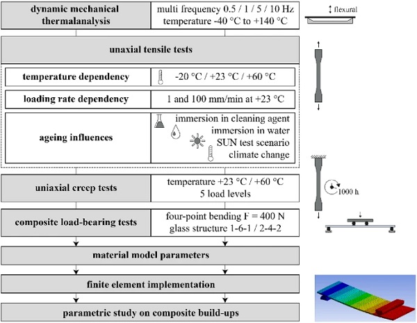
The following paragraphs introduce the individual steps of the study approach shown in Fig. 3:
Dynamic mechanical thermal analysis (DMTA) The DMTA examines the thermodynamic and viscoelastic behaviour and glass transition of the PMMA interlayer core. A defined temperature-frequency program in a three-point bending flexural oscillation mode determines the viscoelastic properties. The temperatures range from –40∘C to C+140∘C (1 K/min heating rate) in multi-frequency stress sweeps (0.5, 1, 5 and 10 Hz).
Uniaxial tensile tests The uniaxial quasi-static tensile tests (DIN EN ISO 527-2:2012-06 2012) evaluate the in-plane stress-strain behaviour, stiffness and failure characteristics of the PMMA interlayer core on mechanically processed dumbbell test specimens Type 1B (DIN EN ISO 3167:2014-11 2014). The initial mechanical properties are examined at temperatures of –20, +23 and +60∘C at a strain-rate of 1 mm/min. Furthermore, the load-dependent behaviour is evaluated at standard (1 mm/min) and high loading rate (100 mm/min) at +23∘ C. Artificial ageing scenarios examine the material’s durability and resistance to potential environmental influences. A comparison of residual material properties with the initial properties demonstrates the ageing effects on the material behaviour. Four different ageing scenarios are examined:
- cleaning: immersion in façade cleaning agent at a temperature of +45 ∘C+45 ∘C for 500 hours according to (DIN EN ISO 175:2011-03 2011; ETAG 002-1 2012).
- water: immersion in demineralised water at a temperature of +45 ∘C+45 ∘C for 500 hours according to (ETAG 002-1 2012).
- SUN: combined exposure to high temperature (+65 ∘C+65 ∘C), UV radiation (550W/m2550W/m2) and demineralised water at +45∘C+45∘C for 500 hours (250 cycles) according to (DIN EN ISO 4892-2:2013-06 2013; DIN EN ISO 11431:2003-01 2003).
- climate: cyclic climate change test according to (DIN EN ISO 9142:2004-05 2004); modified cycle D3: temperatures ranging from –20 ∘C20 ∘C to +80 ∘C+80 ∘C at a high relative humidity of up to 95% for 504 hours (21 cycles).
Table 1 Summary of material properties applied in the research according to technical data sheets and standards - Full size table
Uniaxial creep tests The uniaxial tensile creep tests according to (DIN EN ISO 899-1:2018-03 2018) reveal the viscoelastic creep behaviour of the PMMA interlayer core over 1000 hours. Tests were performed at room (C+23 ∘C) and elevated temperature (+60 ∘C) according to relevant temperatures for laminated glass following (DIN EN 16613:2020-01 2020). Five different stress levels ranging from 5% to 65% of short-term initial strength were applied.
Composite load-bearing tests The composite four-point bending tests were conducted according to (DIN EN 12337-1:2000-11 2000) to describe the load-bearing behaviour in bending. As numerous test specimens are required for statistical strength evaluation, this paper addresses the intact load-bearing behaviour in non-destructive tests. Two test series of glass–plastic-composite panels of a total thickness of 8 mm are examined and compared to conventional monolithic and laminated glass of equivalent thickness. The composite build-ups consist of thin glass faces of 1 and 2 mm ANG with a corresponding PMMA core of 6 and 4 mm thickness.
Material model parameters and finite element implementation Based on the material examination dataset, linear material model parameters with a focus on the temperature-dependent short-term material behaviour of the PMMA interlayer core are derived and implemented into FE software. Experimental test results serve to validate the uniaxial tensile simulations and the implemented material model parameters within the linear elastic range. Subsequent numerical simulations of four-point bending allow for extended stress analysis in the PMMA interlayer core and over the whole panel as well as an extrapolation of load-bearing behaviour to different build-ups and increased load levels.
Parametric study The stiffness study, performed on the basis of the four-point bending simulations, evaluates how the Young’s modulus of the PMMA interlayer core affects the overall composite bending stiffness and the expected stress distribution through the centre cross-section. It also assesses the temperature dependency and reviews the limits of the implemented linear material model parameters. The subsequent parametric study extends the investigation of the composite load-bearing behaviour to a wide collection of glass–plastic-composites and laminated glass panels in build-ups ranging from 6 to 15 mm in total thickness.
The composite stiffness, expressed as Young’s modulus of an equivalent homogeneous material, is individually evaluated by the centre panel deflection and the application of Euler-Bernoulli beam theory. Following from this, the specific stiffness (Gooch 2011) or specific modulus, defined as Young‘s modulus per unit mass density, is determined for the analysed build-ups. The specific stiffness quantifies the potential of the composites and permits the evaluation of the lightweight performance of glass–plastic-composite panels in comparison with conventional glass panels and other composite materials. It further provides a first rough design of the composite panels as substitution for monolithic glass by means of the equivalent glass thickness approach.
Experimental investigation
Materials
Dumbbell test specimens for the PMMA interlayer core material investigations were manufactured by the representative radical polymerisation cast process for glass–plastic-composite panels in the reference composition. The commercial monomer methyl methacrylate (Evonik Industries AG: MMA with 10 ppm Hydroquinone monomethyl ether MEHQ stabilizer) with UV absorbers was used in the study. To achieve the highest dimensional accuracy, all test specimens were cut out of homogeneous sheet material by waterjet processing. The processing quality may affect the ultimate strength due to quality differences compared to in-shape cast or polished specimens.
Such influences were accepted within the study and considered in the evaluation. Composite test specimens were manufactured in panel sizes of 2.1×1.3 m22.1×1.3 m2 and afterwards cut in size via waterjet processing. The composite specimens underwent additional chamfering (1 mm) and polishing in a vertical glass edge-grinding machine. Glass supplier of the thin glass faces was Pilkington (Pilkington Group Limited 2002). Conventional fully tempered glass (FTG) and laminated glass (LG) specimens used as a reference came from a standard glass supplier. For conventional glass, material properties according to (DIN EN 572-1:2016-06 2016; DIN 18008-1:2020-05 2019) were considered. Table 1 summarises the material properties.
Dynamic mechanical thermal analysis
Test method
The mechanical properties of viscoelastic polymers, such as thermoplastic PMMA, are highly dependent on temperature, time and loading (Grellmann and Seidler 2013; Schwarzl 1990). The DMTA is a method for determining the thermodynamic and viscoelastic properties of polymers by applying a sinusoidal force to the material test sample and measuring the responding sinusoidal deformation (DIN EN ISO 6721-1:2019-09 2019; Grellmann and Seidler 2013).
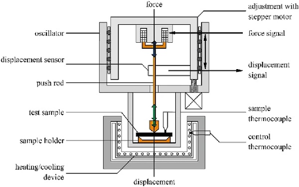
Viscoelastic material behaviour causes a shift between the applied force (stress) and the corresponding deformation (strain). The deviation is referred to as the phase shift δ. Applying the Fourier Transformation results in storage modulus E′ (refers to elastic materials stiffness) and loss modulus E′′ (released energy as heat). The loss factor tan δ defines the ratio between E′′ and E′ and describes the viscoelastic damping. The DMTA sensitively detects state changes of polymers that can be directly associated with the change in the physical modules. Figure 4 shows the DMTA test setup and its individual components.
Analysis
The presented analysis focuses on the determination of the storage modulus E′ and loss factor tan δ that both define the corresponding glass transition range (transition between glassy energy elastic to rubbery entropy elastic state). Three test samples with the dimensions of 30 x 6 x1.2 mm³ were tested in three-point bending mode (20 mm free bending length) that is recommended for materials with high storage modulus (Netzsch 2009). The displacement-controlled bending amplitude amounted to 30 μm. Figure 5 shows the thermograms presenting storage modulus E′ and the loss factor tan δ curves of the PMMA (mean values of three samples) for altering frequencies in the temperature range from –20 to +140∘C.
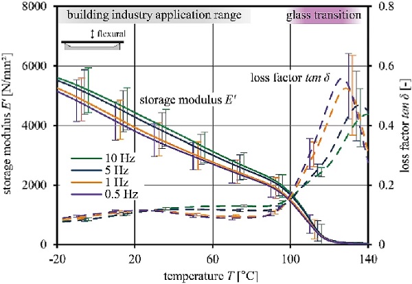
The thermomechanical behaviour of the PMMA interlayer core manifests continuous decrease in stiffness (storage modulus E′) with increasing temperature, which is typical for thermoplastic polymers. Deviations are specified by error indicators. Slight differences in thermomechanical behaviour at altering frequencies indicate marginal frequency-dependent behaviour. The storage modulus significantly decreases at appx. +100 ∘C and characterizes the relaxation transition (glass transition). Beta-relaxations due to local mobility of side groups are observed in the region between 25 to 30∘C and confirm the findings in (Ionita et al. 2015; Menard and Menard 2020).
The glass transition is determined as a temperature range between the onset of the storage modulus curve (start of softening) and the maximum of the loss modulus curve (end of glass transition) according to (ASTM D4065-20 2020; ASTM E1640-18 2018). It ranges from Tg,onset= +97.0 ∘C (0.5 Hz) to Tg,peak=+135.3 ∘C (10 Hz). The softening starts 17 K above the application temperature range of the building industry. The PMMA exhibits a storage modulus >2000 N/mm² until +80 ∘C. Low energy dissipation (loss factor tan δ <0.12) indicates mainly elastic behaviour.
The DMTA results fit with the information from literature on conventional PMMA investigations (Menges et al. 2011). The characteristics of the glass transition area itself and the entropy elastic state do not play a significant role for the design and are not further studied within this paper. In summary, the DMTA verifies high elastic stiffness and no phase change of the PMMA at the building application relevant temperatures. This leads to desirable material properties of the PMMA interlayer core for the application in composite panels for the building industry.
Uniaxial tensile tests
Test method
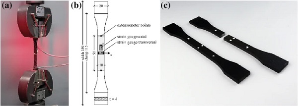
The uniaxial tensile test setup and specimen preparation are shown in Fig. 6. A test rig Instron UPM 5881 in combination with an optical extensometer measures contactless nominal (engineering) axial and transversal strains using high contrast measuring points (white marks on black painted specimens). The test setup was equipped with an environmental test chamber and feedback temperature control. The standard loading-rate was set to 1 mm/min for the evaluation of tensile properties according to (DIN EN ISO 527-2:2012-06 2012). Additional polymer strain gauges precisely evaluate the Poisson’s ratio in the centre of the specimen (backside) from transversal to axial strains at +23 ∘C. Within each test series, minimum five test specimens were examined and their nominal stress ε-nominal strain σ behaviour, tensile Young’s modulus Et, ultimate strength σu and elongation at break εu characterised.
Reference material behaviour
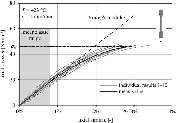
Figure 7 shows the reference engineering stress-strain diagram as mean value regression curve (bold black) and the individual test results (grey) at a strain-rate v= 1 mm/min at laboratory conditions +23 ∘C/50% RH (DIN EN ISO 291:2008-08 2008). The chart illustrates ideal linear stress-strain behaviour of the PMMA until approximately 0.8% strain (deviation from linear behaviour: 2%). Within the ideal linear elastic range, the tensile Young’s modulus Et = σ/ε is derived using the gradient (dashed line). After approximately 0.8% axial strain, the material behaves viscoelastic until brittle failure. No yield point indicates an onset of plastic deformation. The PMMA exhibits stiff but brittle behaviour and fails on average at strains of 2.92% at a strength of 46.2 N/mm². The Poisson’s ratio at +23 ∘C at a strain-rate of 1 mm/min is evaluated to 0.37, between 0.3 to 1.5% strain.
Temperature and loading strainrate dependency
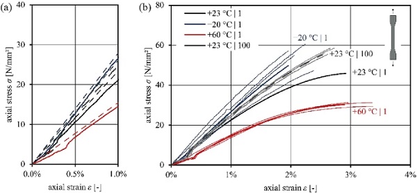
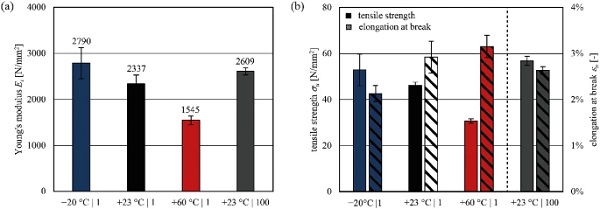
Composite panels in the building industry are exposed to different loadings as well as environmental conditions. The requirements can be associated to those of conventional laminated glass (DIN EN 16613:2020-01 2020; DIN EN ISO 12543-2:2011-12 2011). Hence, the limits of low (–20 ∘C) and high temperatures (+60 ∘C) are considered. Figures 8 and 9 compare the stress-strain behaviour at different temperatures at standard (1 mm/min) and at high (100 mm/min at +23 ∘C) loading strain-rates.
The effects of temperature are clearly visible by an increased strength and brittleness at low temperatures, whereas the PMMA softens at high temperatures, leading to increased elongation at break and decreased tensile strength. The high loading strain-rate results in higher ultimate strength with lower elongation at break. Figure 9 summarises and compares the results of short-term tensile testing. The influence of temperature on the stiffness decrease is approximately linear across the considered range of –20∘C and +23∘C to +60∘C, matching the findings in the DMTA.
Ageing influences
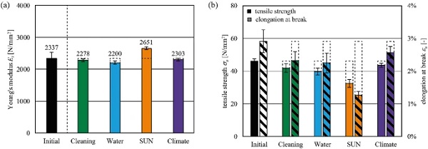
Figure 10 presents the influences of the accelerated ageing scenarios according to the test program. The immersion in cleaning agents and water only slightly influences the material behaviour and properties (Young’s modulus, strength and elongation at break). No differences in the optical appearance were observed after these ageing scenarios. The SUN ageing scenario as combined UV, high temperature and water exposure embrittles the material, which stiffens it (+13%), but significantly lowers the strength (–29%) and elongation at break (–57%) compared to the initial properties. Slight material yellowing was observed. The material strength does not fall below 30 N/mm². The climate ageing scenario very slightly influenced the mechanical properties, with no effects on the optical appearance.
Summary and discussion
The mechanical material properties are summarised in Table 2. The average Xmean of each test series serves as a comparative value of the Young’s modulus, tensile strength and elongation at break to the unaged initial properties (+23 ∘C | 1 mm/min).
Table 2 Short-term mechanical properties of PMMA interlayer core: mean value | standard deviation (ratio: property/initial property); labelling of test series: temperature | loading rate in mm/min - Full size table
The experimental tests on dumbbell specimens of the PMMA interlayer core reveal mainly linear behaviour under quasi-static loads with small strains until brittle failure. The polymer chains of the thermoplastic polymer get more entangled as they soften at higher temperatures. This results in reduced stiffness and lower strength with higher elongation at break. At lower temperatures and higher loading strain-rates, the polymer exhibits stiffer, stronger but more brittle behaviour.
The reference unaged material strength at +23 ∘C | 1 mm/min amounts to 46.2 N/mm² with an elongation at break of 2.9%. The Young’s modulus amounts to 2337 N/mm². Industrially cast or extruded PMMA panels (e.g. PLEXIGLAS®7N) exhibit higher tensile Young’s modulus (3200 N/mm²) and strength (73 N/mm²) with an ultimate strain of 3.5%. These alterations can be assigned to the industrial manufacturing process and the influence of additional processing. The waterjet inlet and outlet cause defects at the specimen edges that may reduce the strength compared to the edge processed/ polished or in form cast specimens. No additional tests were performed to investigate these influences.
The PMMA interlayer core softens at elevated temperatures with lower strength at increased strains. However, even at +60 ∘C, the PMMA exhibits a Young’s modulus of 1545 N/mm². Compared to conventional interlayers for laminated glass, the stiffness is several times higher, even for the stiff PVB or ionoplast interlayers (Kuntsche 2015). Influences of ageing on the PMMA leads to negligible effects on the load-bearing behaviour, apart from the SUN ageing that embrittled the material leading to slightly higher stiffness and reduced strength.
The results demonstrate the high durability of the PMMA interlayer core. In the final application, the glass cover layers additionally protect the PMMA core surfaces from ageing, which further improves the durability in the composite assembly. However, it should be noted that PMMA is highly susceptible to stress corrosion cracking (Andrews and Levy 1974). Cleaning agents with high solvent content, such as acetone or isopropyl alcohol, can lead to visible stress corrosion cracking resulting in reduced strength and premature failure. The contact and exposure to such cleaning agents must be explicitly excluded in application and maintenance.
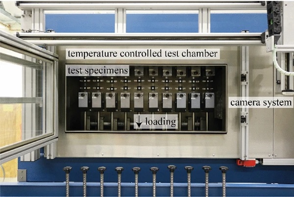
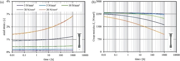
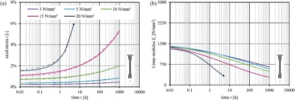
Table 3 Creep modulus for the evaluated stress levels at different temperatures for individual time steps - Full size table
In summary, the experiments on dumbbell test specimens provide an extensive dataset. This allows for the development of a material parameter set for the FE simulations and reliable predictions of the material behaviour of the PMMA and the structural load-bearing behaviour of glass–plastic composite panels in different build-ups.
Uniaxial creep tests
Test method
The Creep modulus is of central importance in the design of plastic materials under long-term loading. Uniaxial creep tests on dumbbell specimens examine the influences of load duration on the mechanical material properties of the PMMA interlayer core. Stress levels of 3, 5, 10, 20 and 30 N/mm² at +23 ∘C and 3, 5, 10, 15 and 20 N/mm² at +60 ∘C reveal stress-dependent viscoelastic material behaviour. Two test specimens per series were examined in a creep test rig (see Fig. 11). Lowering the weights in a pneumatic system started the loading shock-free.
The initial strain is considered at a measurement time of t = 10 s. This eliminates material and measurement influences of load introduction. In order to correct the non-uniform load introduction and to unify the test results, the initial strains are derived using the initial Young’s modulus from the short-term test results at the corresponding temperature (compare equation 1). Hence, the initial strain, at 10 s after the load introduction, corresponds with the elastic component of the material.

Optical extensometer contactlessly measured the axial strains over a time period of 1000 h with (at least) the measurement frequencies defined in (DIN EN ISO 899-1:2018-03 2018).
Creep behaviour
The strain–time diagrams in Figs. 12 and 13 present the temperature and stress-dependent creep behaviour. The dashed lines indicate the mean values, whereas the solid lines approximate the strain behaviour over time using power law function according to equation 2 (Findley 1976). The derived Creep modulus Ec is given in the corresponding Creep modulus–time diagrams.
![]()
m, n material constants from regression optimisation.
The viscoelastic strain component increases with progressive load duration and grows at elevated temperatures and levels (Grellmann and Seidler 2013). Linear viscoelasticity of the PMMA leads to a linear correlation between stress and strain, independent of the load duration (Schwarzl 1990). At higher load durations and higher stress levels σ > 10 N/mm² the PMMA interlayer core exhibits increasingly nonlinear-viscoelastic behaviour. (Zhao et al. 2008) specifies a critical stress limit of 18 N/mm² for the transition of linear- to nonlinear-viscoelastic creep at room temperature for a commercial PMMA with a glass transition temperature of about 105 ∘C. The increasing nonlinear-viscoelastic effects are enhanced by elevated temperatures and disproportionately increase with load duration (Schwarzl 1990). Table 3 summarises the results at different stress levels for the time steps of 1 h and 1000 h.
The creep coefficient cccc, following equation 3, specifies the creep behaviour and respectively the temporal decrease of material stiffness by relating the end value of Young’s modulus Ec,1000 h to a reference value Ec,initial or Ec,1h. Since the temperature and applied load level affect the creep rate, different operating temperatures of polymers must be considered in the design stage.

Table 4 summarises the evaluated creep coefficients for all the tested configurations by using the initial Young’s modulus and the Young’s modulus after 1 h.
Table 4 Creep coefficients of PMMA interlayer core at investigated temperatures and stress levels - Full size table
To classify the results, the stresses in the PMMA interlayer core in the composite assembly were roughly calculated under bending loads. The precise interlayer core stresses will be presented in section 3.4. The stress levels in the composite assembly under bending loads are expected not to exceed 5 N/mm², as the glass stresses would lead to an early failure. Therefore, at the stress levels up to 5 N/mm² at room temperature, the creep coefficient amounts to 0.96. This indicates minimal creep tendency and nearly constant stiffness for the expected loading on glass–plastic-composite panels in use. At elevated temperatures and higher stress levels, a more significant creep influence on the PMMA is to be expected and must be considered in the design of glass–plastic-composite panels.
To get a more widespread dataset, further test series at a lower temperature limit for laminated glass (20 ∘C) and additional stress levels could be carried out. However, at lower temperatures the PMMA behaves stiffer and creeps less, leading to beneficial material properties for the design of glass–plastic-composite panels. The conducted experimental investigations cover the important design-relevant temperatures and stress levels sufficiently for building applications. Based on the experimental dataset, material models for analytical or numerical simulations can be developed in further studies, however, as this exceeds the scope of this paper. Predictive models for creep behaviour of commercially available thermoplastic PMMA are mainly established on exponential functions (Arnold and White 1995) also taking into account creep rupture (Crissman and McKenna 1987), generalized Maxwell models, as developed in (Rühl et al. 2017), or generalized Maxwell models as a generation of Prony-Series (Fernández et al. 2011).
Composite load-bearing tests
Test method
Four-point bending tests according to (DIN EN 1288-3:2000-09 2000) examine the load-bearing behaviour and calculate the linear composite stiffness and glass stress response. Minimum five test specimens per series were loaded up to a force level of 400 N (load application speed of 400 N/min) at +23 ∘C. A detailed description and evaluation of composite load-bearing tests are presented in (Hána and Weller 2019b). Axial strain gauges on the glass surfaces (centre top and bottom) and vertical displacement sensors in the centre, centre edge and below one bending roller (see Fig. 14) recorded the strains in x direction and deflections in z direction. Two series, 1ANG-6PMMA-1ANG and 2ANG-6PMMA-2ANG, were tested. Monolithic 8 mm (FTG) thick glass and laminated glass composed of two layers of 4 mm ANG with a standard PVB interlayer with a thickness of 0.76 mm (LG 44.2 - PVB) were tested to compare the load-bearing behaviour to conventional glass panels.

Composite load-bearing behaviour
Figure 15 shows the load-bearing behaviour of the test series (mean regression curve) in a force-deflection and force-stress (strain gauge SG1) diagram. To evaluate the specific glass stresses from measured strains, Young’s moduli according to the thin glass manufacturer’s technical data sheet and the standards for conventional glass are applied (see Table 1).
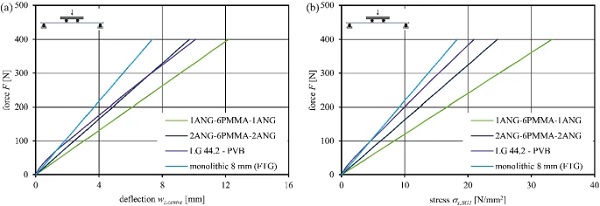
The composite panels exhibit linear load-bearing behaviour (coefficient of determination R² > 0.999). No creep effects of the interlayer material are observed in the short-term tests. This proves the persistent short-term stiffness of the PMMA interlayer core and complete connection between the layers. The glass cover layer thicknesses significantly influence the load-bearing behaviour (deflection and stress response) according to the overall composite panel stiffness. Laminated glass with standard PVB interlayer exhibits significant initial shear coupling. However, standard PVB softens already at room temperature leading to time-dependent creep. This lowers the coupling effect of the glass panes during the experiments and results in nonlinear deflection and glass stress increase (see Fig. 15). The initially very high stiffness up to a force level of around 70 N can be assigned to the sensitivity of the test machinery—the faster load application speed at the start of testing until the machine had adjusted.
For a comparison of the bending stiffness, the corresponding Young’s moduli of the specimens (Ecomposite) were derived from the maximum centre deflection by the application of the Euler–Bernoulli beam theory as conducted in (Hána and Weller 2019b). It assumes the elastic modulus in accordance with Hooke’s Law and that the plane sections of the composite remain plane and normal to the axis of the beam. This can be assumed for materials with high shear stiffness, as used in glass–plastic-composite panels, and full shear connection due to the permanent chemical bond between the glass and PMMA interface. The flexural rigidity and Young’s modulus of the composite in bending can be analytically derived from the centre deflection and used to describe the stiffness of an equivalent homogeneous material. The monolithic glass as a reference represents the limit for full coupling and corresponding glass bending stiffness as derived Young’s modulus. The evaluated results for the tested build-ups are summarised in Table 5.
Table 5 Evaluated results from composite tests (force level F=400N) - Full size table
The monolithic glass Young’s modulus matching the reference value of 70 000 N/mm² (deviation ++1.6%) validates the test method. LG 44.2—PVB exhibits a stiffness of 41 818 N/mm² (60% of monolithic glass) due to only partial shear coupling at +23 ∘C. The stiffness of the glass–plastic-composite panels is sensitive to the interlayer core-to-cover layer ratio. In summary, the weight can be highly reduced by 39% or by 26%, still offering composite Young’s moduli of 61% and 93% for the assembly with 1 mm or 2 mm thin glass cover layers. The tensile glass stresses σx,SG1 in the composites are, however, larger compared to those in monolithic glass as the glass is acting with a higher load fraction due to the glass-to-PMMA Young’s modulus ratio and the corresponding layer thicknesses.
This evaluation forms the basis for comparison of the individual composite build-ups and corresponding conventional glass panels. Wide ranging analytical sandwich beam theories can also be applied to calculate the deformation and stresses in composite structures (Altenbach et al. 2004; Stamm and Witte 1974; Wölfel 1987). One is referred to (Hána and Weller 2019b) for the application of sandwich beam theory (Wölfel 1987) assumptions on glass–plastic composite panels. It was shown that an approximation is possible, however, only to a limited degree of precision. For a more detailed analysis, FE simulations using the material dataset are used to extrapolate the load-bearing behaviour to varying build-ups. This also allows for the observation of detailed glass and PMMA interlayer core stresses over the full panel, even at higher load levels, and a direct comparison of various composite build-ups to conventional glass panels.
Numerical simulations and parametric study
This section describes the implementation of the temperature-dependent material parameters (–20, +23 and +60 ∘C) in the commercial FE software ANSYS Workbench 19.3 and subsequent numerical simulations of the uniaxial tensile tests and four-point bending tests. The focus is set on the short-term time independent linear material behaviour as the stresses in the interlayer are expected not to exceed the linear elastic limit in the composite load-bearing behaviour. This assumption is verified in the following parts of this paper. Post-processing of the simulation results examines the load-bearing behaviour and the detailed stress distributions in the panel cross section.
The conducted experimental uniaxial quasi-static tensile test are compared to the numerical implementation of the linear material parameters and checked for deviations within the linear elastic range. The experimental composite tests results validate the four-point bending FE model. The influence of the PMMA interlayer core stiffness on the bending stiffness, i.e. the composite Young’s modulus, and PMMA interlayer core stresses are briefly analysed. The following parametric study extends the composite load-bearing behaviour analysis to other build-ups and examines the resulting performance in comparison with conventional glass panels.
Material parameters
Isotropic linear elastic material behaviour by the definition of Young’s modulus and Poisson’s ratio is implemented. The isotropic definition similarly considers tension, shear and compression stress states. The material parameters are assumed temperature-dependent according to experimentally evaluated properties (see table 6). Since the Poisson’s ratio of the thermoplastic PMMA changes insignificantly across the temperature range from 20 ∘C to +60 ∘C up to strains of around 2% and the evaluation for every temperature and loading strain-rate is very complex as well as susceptible to measurement errors, the examined Poisson’s ratio of 0.37 at +23 ∘C | 1 mm is generally applied. Only minor deviations are expected compared to a more specific implementation of the Poisson’s ratio. No failure mechanisms of the polymer PMMA are considered within the simulations as significantly higher glass tensile stresses are expected to be decisive in the ultimate design.
Table 6 Isotropic elastic material parameters for the PMMA interlayer core resulting from the experimental test results - Full size table
Uniaxial tensile simulations
FE simulations of the uniaxial tensile test inspect the material parameter assumptions and FE model settings. Dumbbell specimens with fixed support conditions and force applied on the opposite side are modelled. Higher order 3D 20-node solid elements (SOLID186) with full integration of the quadratic elements are used. A displacement-controlled loading in –x direction simulates the behaviour considering large deflections. The resulting axial stress-axial strain diagram in Fig. 16a compares the numerical simulations with the experiments at temperatures of –20, +23 and +60∘C.
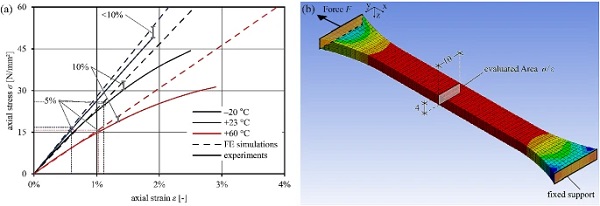
Table 7 Introduction of simulation properties - Full size table
The isotropic linear model overestimates the stiffness at increasing strains and increasingly deviates from the test results. The divergences for the overestimation of stiffness compared to the experiments are marked by error bars for 5 and 10% divergence. Up to stresses of 15.9 (–20 ∘C), 24.7 (+23 ∘C) and 15.0 N/mm² (+60 ∘C) the linear stress-strain behaviour matches the load-bearing behaviour with deviations of less than 5%. The corresponding strains are marked by dashed lines in Fig. 16a. The deviations in the linear elastic range provoke minimal errors across the following simulation; as only low PMMA interlayer core stresses are expected in the composite bending mode, linear elastic material parameter assumptions permit sufficiently correct evaluation of the composite material load-bearing behaviour in the FE analysis.

Four-point bending simulations
An FE model for the simulation of the composite load-bearing behaviour is developed following the four-point bending test setup. The material parameters for glass according to Table 1 assume linear isotropic elasticity. The user defined material parameters implement the linear isotropic elastic properties of the PMMA interlayer core according to Table 6. Prony series coefficients from (Andreozzi et al. 2014) describe the complex viscoelastic material behaviour for a standard PVB interlayer in laminated glass.
All solid bodies of the composite are bonded assuming full force transmission at the interfaces between the individual layers. Based on the preliminary convergence study with refined meshing and multiple segmentations over the thickness, the appropriate mesh size is set to 5 mm. Mid-size nodes in Solid186 elements with full integration of quadratic elements serve for proper identification of stress distributions. Table 7 introduces the simulation properties.
Figure 17 shows the FE model and detailed build-up with mesh sizing. The implemented layer thicknesses come from the mean values of measurements within the experimental test series. Symmetry conditions in x-z and y-z plane define the quarter symmetry. For accurate simulations, the bearing and bending rollers are simulated as structural steel with a nonlinear contact approach as proposed in (Müller-Braun and Schneider 2017). The bending roller and support roller are defined with frictionless contact surfaces to the glass surface (target).
Augmented Lagrange formulation with the detection method of nodal point normal to target surface is used. The pinball radius for finding the contact to the target was set to 5 mm. Stepwise load-introduction (10 steps with minimum 10 substeps) considers structurally nonlinear behaviour that affects the contact status of the rollers to the glass during bending. Force-controlled loading is applied on the bending roller in ++z direction. The bending roller is fixed for movements in x and y direction, whereas the support roller is fully fixed at the bottom. Stresses and deflections at the measurement points corresponding with the experiments are used to validate the FE model.
Table 8 presents the measured and simulated deflections and stresses at the force level of 400 N. For the monolithic glass, the deflections and stresses in the centre are further analytically calculated according to the Euler-Bernoulli beam theory. The relative deviations evaluate the agreement of the numerical calculations with the measured/ analytical values.
Table 8 Comparison of experimental, analytical (Euler-Bernoulli beam theory) and numerical results (ANSYS) at force level of F = 400 N - Full size table

The comparison shows a generally good match between the numerical simulations and experimental measurements as well as analytical calculations. The exceptionally high deviations observed for the monolithic glass test series are assigned to misapplication of the strain gauge series that was found at the end of the tests. A further repetition of the test series was not possible. However, the analytical beam theory allows for verification of the numerical simulations with deflection and stress deviation of -2.3% for wcentre, 1.9% for σx,SG1 and -0,1% for σx,SG2.
The exceptionally high deviations of deflection and stresses in laminated glass can be assigned to the faster load application speed up to 70 N at the start of testing until the machine had adjusted. This led to initially higher PVB short-term stiffness resulting in lower deflections and glass stresses than calculated in the numerical simulations applying the Prony shear relaxation material model. In all cases, the FE model slightly overestimates the stresses and deformations for glass–plastic-composite panels, leading to conservative simulations. In conclusion, the composite FE model is suitable for numerical predictions that can be applied to alternative scenarios in varying geometries, panel compositions and support conditions.
Evaluated stress distributions through the panel thickness (see Fig. 18) based on the FE simulations assess the PMMA interlayer core stresses. Monolithic glass with a typical monolithic stress distribution and laminated glass with partial shear coupling serve as references for the conventional glass structures. Even laminated glass with standard PVB exhibits shear coupling between the glass panes that, however, significantly lowers over time due to time-dependent creep influences. The stresses in the interlayer are negligibly small and not evaluated in detail.
The monolithic glass shows slight differences in compression and tension values. These derive from the additional normal stresses generated by the shortening of the bearing at increased panel deflections and the large deflection consideration in the FE simulations (Baratta et al. 1987; Grellmann and Seidler 2013). The laminated glass shows a stress distribution for partial shear interaction with tension and compression in each glass layer.
The stress evaluation in the glass–plastic-composite panels show pure compression in the top and pure tension in the bottom glass cover layers. The neutral axis is situated about the centre of the cross section within the polymer interlayer core. The experimental mean tensile strength of the PMMA interlayer core is utilised to only 1.9% for 1AN 6PMMA - 1AN and 1.1% for 2AN 4PMMA - 2AN. The low stress levels in the interlayer core (< 1 N/mm²) in tension guarantee minimal creep at a temperature of +23 ∘C. The strength utilisation of the PMMA is less than 2%, whereas the glass stresses are by a multiple larger and utilised up to 78%.
Nonlinear stress-strain behaviour of the PMMA at increasing strains does not become relevant in the investigated range of the examined composite build-ups and loading conditions, as the linear elastic range is not exceeded. Only at larger stresses and strains of the interlayer core, the linear isotropic elasticity increasingly deviates from the actual stress-strain behaviour and causes errors by overestimating the stiffness. Furthermore, beyond the linear elastic range, stresses in the PMMA interlayer core are redistributed in viscoelastic and plastic range of the polymer and lead to propagated nonlinear stress distributions and an upwards shift of the neutral axis due to the separate tension and compression behaviour (Schwarzl 1990).
Influence of stiffness
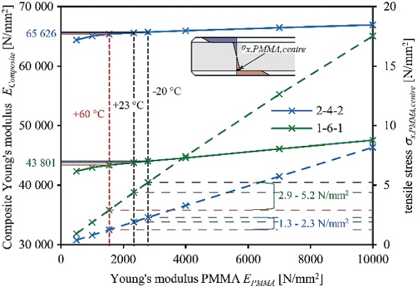
In order to evaluate the influence of the PMMA interlayer core Young’s modulus on the overall bending stiffness of the composite with corresponding stresses, numerical four-point bending simulations are carried out with a parameterisation of the PMMA Young’s modulus for –20, +23 and +60 ∘C (see Table 6) and extended to properties varying from 500 to 10 000 N/mm² . The simulations are performed with an extended force level of 2000 N. Figure 19 describes the composite Young’s modulus (first y axis) for composite build-ups of 8 mm total thickness with 1 and 2 mm glass cover layers (1-6-1 and 2-4-2) calculated from centre deflection by the application of the Euler–Bernoulli beam theory.
The centre glass tensile stresses amount to 170 N/mm² (1-6-1) and 115 N/mm² (2-4-2). The derived composite Young’s modulus shows an insignificant change of less than 1% at –20 and +60∘C compared to the reference case at +23 ∘C. This shows an insignificant change in the load-bearing behaviour due to temperature-dependent PMMA Young’s modulus for the building industry relevant temperatures. Even a very low interlayer Young’s modulus of 500 N/mm² or a very high Young’s modulus of 10 000 N/mm² influences the derived composite Young’s modulus by a limited degree of –3.4% to ++8.6% for 1-6-1 and –1.8% to +2.0% for 2-4-2.
The normal tensile stresses in x direction of the PMMA interlayer core were assessed in the stiffness analysis in Fig. 19 on the second y axis. The stresses linearly increase with increased PMMA interlayer core stiffness related to Hooke’s Law. The stress-PMMA Young’s modulus slope is highly dependent on the glass-to-cover layer ratio of the composite build-up. However, it demonstrates that in the range of the building industry relevant temperatures (–20 to +60∘C), the PMMA stress-strain behaviour remains linear elastic (see Sect. 4.2). During the following parametric study, it was continuously checked whether the stress-strain behaviour of the PMMA is still in the linear elastic range. Otherwise, the results could significantly deviate from reality and hence, the application of a nonlinear material model would be required to correctly represent the nonlinear PMMA material behaviour.
Parametric study
The following parametric study deploys the PMMA material parameters and four-point bending FE model to evaluate the load-bearing behaviour in different glass and composite build-ups at a temperature of +23 ∘C. The objective is to compare the bending stiffness, examined as composite Young’s modulus, as well as maximum stresses in the individual layers and finally rate the load-bearing performance in relation to lightness by using the unit mass density and derived corresponding specific stiffness of the build-ups. All calculations were performed up to a force level of 2000 N with a load application speed of 400 N per min.
Glass–plastic-composite panel build-up parameters are defined ranging from 6 to 15 mm nominal total thickness following conventional standardised thicknesses for glass (DIN EN 572-1:2016-06 2016). The material assumptions and simulation properties are described in Sect. 4.3. Symmetric laminated glass with standard PVB and monolithic glass serve as a reference. All parameters are summarised in Table 9.
Table 9 Introduction of parameter sets for the investigated build-ups - Full size table
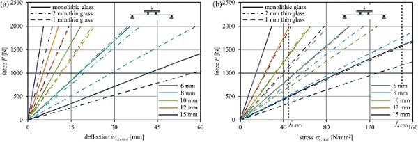
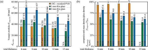
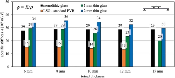
Figure 20 presents the evaluated results for the different build-ups of glass–plastic-composites in force-deflection and force-stress charts with monolithic glass as a reference. The lower the polymer-to-glass ratio, the closer the charts follow the monolithic glass-like behaviour. The characteristic strength of ANG fk,ANG= 45 N/mm² according to (DIN EN 572-1:2016-06 2016) are exceeded for all the evaluated glass–plastic-composite structures at 2000 N. Hence, the force-stress charts define the maximum characteristic capacity for the evaluated composite build-up. Improvements of the maximum capacity could be achieved by the application of CSG with a characteristic strength fk,CSG = 150 N/mm² according to (DIN EN 12337-1:2000-11 2000).
These standard specifications represent an essential reference support for CSG strength even if, till now, the strength value remains quite general and is significantly dependent on the glass composition and glass strengthening process parameters (Mognato et al. 2016). The limits are similarly provided in the force-stress charts and indicate the maximum load-bearing capacity with CSG cover layers. Significantly higher capacities are reached.
To classify the results, the decisive tensile stresses of PMMA and glass are evaluated and compared to the characteristic material strength. Table 10 presents the decisive tensile stresses (force level F = 2000 N) at the centre-span cross section and evaluates the individual strength utilisation.
The PMMA interlayer core tensile stresses do not exceed 6.37 N/mm² and remain in linear elastic range with a 14% utilisation of PMMA tensile strength, whereas the glass strength of ANG is exceeded in all of the cases at the force level of 2000 N.
Table 10 Normal tensile stresses and strength utilisation of glass and PMMA at a force level of 2000 N for glas–plastic-composite panels with 1 mm and 2 mm thin glass cover layers - Full size table
To compare the composite bending stiffness to conventional glass stiffness, the composite Young’s modulus as extensional stiffness of an equivalent homogeneous plate was derived according to Sect. 3.5. Based on the composite Young’s modulus, an equivalent glass thicknesses dequ,glass is calculated for the individual build-ups according to equation 4. This provides a quick comparison to the conventional monolithic glass.

Figure 21a describes the evaluated composite Young’s moduli for the glass–plastic-composites that quantifies the flexural stiffness according to the individual nominal build-up. The equivalent glass thickness is described in the bottom of the bars in Fig. 21a. Figure 21b describes the nominal weight by unit mass density-to-glass density ratio (ρcomposite/ρglass) that is determined by applying the individual material densities for each layer (see Table 1). The specific unit mass density is provided in the bottom of the bars for each build-up.
The composite Young’s modulus for panels with 1 mm thin glass cover layers decreases from 47 878 N/mm² at 6 mm to 27 460 N/mm² at 15 mm total thickness, however, resulting in reduced weight from 65 to 54% of conventional glass mass density, respectively. The composites with 2 mm thin glass cover layers behave significantly stiffer. Hence, the Young’s modulus amounts to nearly monolithic glass stiffness (69 783 N/mm²) at 6 mm, that reduces to 45 662 N/mm² at 15 mm total thickness. The unit mass density is still reduced ranging from 82 to 62% of the conventional glass density.
The equivalent composite stiffness of the LSG slightly decreases at higher nominal total glass thickness due to the lower shear coupling effects at increased glass to interlayer ratio, whereas the unit mass density of the LSG linearly increases to a very low degree with increased glass-to-interlayer ratio. This evaluation shows a high dependence of the composite Young’s modulus on the glass-to-interlayer core ratio. However, the composite unit mass density needs to be taken into consideration in equal shares for effective weight reduction. In summary, this leads to a quick overview of the composite Young’s modulus and weight reduction in comparison with the monolithic glass and provides a first rough design tool for composite panels as substitution for conventional glass using the equivalent glass thickness.
Figure 22 presents the detailed evaluation of the specific stiffness φ in bending for the analysed build-ups. This quantifies the lightweight performance as composite Young’s modulus per unit mass density and allows for comparison of glass–plastic-composite panels to conventional glass panels and any other materials.
Conventional monolithic glass offers a specific stiffness of 29 × 106 m²/s², whereas laminated glass with a standard PVB interlayer reaches around 15 to 13 × 106 m²/s² depending on the overall thickness. The partial shear coupling effects in the standard PVB laminates cause relatively low bending stiffness at still high unit mass density. Glass–plastic-composite panels exhibit specific stiffness in relation to the interlayer core-to-cover layer ratio.
Glass–plastic-composites with 2 mm glass cover layers provide the highest specific stiffness in the evaluated range of thicknesses, whereas 1 mm glass cover layers lead to just slightly higher specific stiffness than monolithic glass up to 8 mm total thickness. This is decreasing at thicker build-ups due to a significant decrease in bending stiffness that is not counterbalanced by weight reduction. However, compared to conventional laminated glass, the specific stiffness is significantly improved for all thicknesses due to the high stiffness of the PMMA interlayer core, complete coupling between the layers and the resulting composite load-bearing behaviour.
Discussion
For characterising the mechanical behaviour of the PMMA interlayer core in the FE software, linear isotropic material parameters were derived from the experimental study. This allowed for the simulation of the PMMA material behaviour time independently within the linear elastic range. The material parameter implementation was validated within the linear elastic range and limited by a maximum allowable deviation of 5%.
Four-point bending simulations of the composite and conventional glass panels were conducted to evaluate the general load-bearing behaviour and stress distributions over the centre panel cross sections. The model itself was validated and verified by the experiments and the linear beam theory calculations. All the following evaluations were based on the numerical simulation results. Further possibility is the application of general analytical beam theory for sandwich structures (Stamm and Witte 1974; Zenkert 1997). However, such approaches are limited by support conditions and load cases when designing with glass–plastic-composite panels.
The stiffness analysis has revealed the PMMA Young’s modulus influences on the novel glass–plastic-composite panels for two composite build-ups (1-6-1 and 2-4-2). This analysis specifically addressed the composite Young’s modulus and interlayer core stresses in the glass–plastic-composite panels. It has demonstrated a linear elastic stress-strain behaviour of the PMMA and a limited influence of the composite Young’s modulus within the relevant temperatures in the building industry applications. One should bear in mind that this analysis has not considered the influence of creep on the polymer and all the relevant build-ups in detail, but it has shown a limited influence on the composite Young’s modulus and load-bearing behaviour.
This statement is supported by the examined Young’s moduli at the building industry relevant temperatures in the uniaxial quasi-static tensile tests and time-dependent Creep moduli at relevant stress states in the uniaxial creep tests. In summary, this stiffness analysis proves a predictable and reliable structural behaviour of glass–plastic-composite panels within the addressed requirements of the building industry. Further creep investigations by means of a suitable creep model and FE analysis could provide exact information on the load-bearing behaviour over time but would exceed the scope of this paper.
Subsequent composite investigations have demonstrated the sufficiency of linear isotropic material parameter assumptions of the PMMA for the composite simulations as the interlayer core stresses and strains never exceeded the linear elastic range. No extension to the nonlinear material models is required for bending applications in the building industry. Nevertheless, the linear models overestimate the PMMA interlayer core stiffness at increased strains leading to uncertain simulation results. For simulations of altering applications, where high interlayer core stains are expected, an extension to nonlinear models is recommended.
Consequently, it needs to be continuously checked whether the linear material parameters are still effective, or a nonlinear material model is required to properly simulate the material behaviour at increased strains. Plasticity material models such as multilinear isotropic hardening (MISO) or hyperelastic material models such as Neo-Hookean or Mooney-Rivlin would suit for describing the material behaviour at increased strains exceeding the linear elastic range of the PMMA Further experimental testing is required for full reliable calibration of nonlinear material model parameters as researched in (Arriaga et al. 2007; Bergström 2015; Rühl 2017; Van Lancker et al. 2020). Extended creep material formulations (e.g. Prony shear relaxation models or viscoplasticity material formulations) reliably describe time-dependency. However, this is primarily necessary at high stress levels or elevated temperatures.
From the evaluation of decisive tensile stresses in the parametric study it can be concluded that glass strength is decisive for the design of glass–plastic-composite panels, whereas the PMMA material strength is never exceeded. Maximum 14% utilisation of the PMMA strength was observed. At this state even the CSG tensile strength is regularly exceeded. Accompanying composite bending strength tests prove this statement. Exceeded glass stresses lead to initial glass cracking and causing PMMA fracture right after. The results will be presented in a following publication.
The parametric study has pointed out the lightweight performances of glass–plastic-composite panels by evaluating the composite Young’s modulus, the equivalent glass thickness, and the unit mass density as well as the resulting specific stiffness. Presented diagrams quantify the significant weight reduction at still high Young’s moduli over conventional glass panels and thereby demonstrates the potential of glass–plastic composites for applications in novel lightweight all-glass systems for the building industry. The use of stiff interlayers such as stiff PVB in laminated glass would considerably increase the specific stiffness of laminated glass leading to nearly full shear coupling effects in short-term loadings (Hána et al. 2019a).
This behaviour is adequately represented by the limit of the full shear coupling as monolithic glass. However, at higher temperatures and under long-term loading even stiff interlayers soften and are susceptible to creep lowering the specific stiffness significantly. Only very stiff ionoplast interlayers offer high long-term performance with minimal creep, even at elevated temperatures. (Hána et al. 2019a) compared the long-term performance of glass–plastic-composite panels to conventional laminated glass with standard and stiff PVB at room temperature.
The examined long-term behaviour showed a clear preference of glass–plastic-composite panels over conventional laminated glass in terms of long-term stability. One should bear in mind that the specific stiffness is not considering material strength, which often becomes decisive for connection joints and point fixings due to stress concentrations. Especially, the improved strength of tempered glass reveals significant advantages in strength over glass–plastic-composites with cover layers of ANG.
While the choice of specimen in other thin glass research activities focuses on the use of chemically strengthened glass, this publication referred mainly to annealed glass cover layers. The question arises: What is the most suitable cover layer glass type for glass–plastic-composites, also with respect to availability and composite strength? The manufacturing and subsequent composite processing as well as the availability of thin glass in architectural dimensions causes the current main limitation. Moreover, to shape the panels, cuttable glass is required.
Annealed glass cover layers allow for cutting and edge treatment, as for conventional glass. The cutting of chemically strengthened glass to size is highly dependent on the strengthening parameters. Furthermore, cut edges and the interference with the initial compressive stress state will result in reduced edge strength (Karlsson et al. 2010; Mognato et al. 2016). Studies with varying types of glass and optimisation of the cutting processes offer further development potential for realizing remarkably increased strength of glass–plastic-composite panels.
Limitations to the application of the glass-plastic composite panels arise from the general brittle failure characteristics. It is important to discuss the brittle failure of the PMMA interlayer core that does not provide residual capacity in glass–plastic-composite assembly compared to a conventional laminated safety glass. To overcome the shortcomings and achieve desired ductility as well as safe failure in the context of post-fracture performance, further developments and investigations are necessary.
Solutions may include the modification of the PMMA interlayer core with nanoparticles leading to enhanced ductility even after glass breakage or processing into laminated structures. These approaches counter the brittle failure of the PMMA and lead to desired safe failure and residual capacities required for the structural glass applications. However, lamination results in higher costs and leads to shear coupling considerations of the conventional laminated glass. This would moderate the actual composite load-bearing performance but allow for a wider range of applications where safe failure is required.
Summary, conclusions and outlook
This research comprised the extended experimental material investigations on PMMA and glass–plastic-composite panels as well as the subsequent numerical simulations and investigations of the stiffness and the parametric study. The experimental investigations addressed the lacking mechanical properties of the modified PMMA interlayer core for glass–plastic-composites in DMTA, uniaxial quasi-static tensile and uniaxial creep tests as well as durability tests according to the building industry requirements.
The investigations have demonstrated sufficient stiffness, strength as well as durability of the used PMMA under quasi-static loads with small strains until brittle failure. This examination led to a comprehensive PMMA material dataset suitable for the design of glass–plastic-composite panels that is now open for use in variety of potential applications. Furthermore, the four-point bending tests have shown the linear load-bearing behaviour, high stiffness and adhesion to glass leading to full force transfer between the layers of the glass–plastic-composite panels.
The material dataset was implemented into an FE software by using the linear isotropic material parameters. Experimental tensile tests have validated the material model parameters to a confident degree. The PMMA tensile stresses in composite assembly do not exceed the linear elastic limit. In conclusion the material model parameters are suitable for the investigation and design of glass–plastic composite for building industry relevant applications in bending. As the PMMA strength is not critical, the glass strength, even of chemically strengthened glass becomes decisive and limits the design of the composites.
The stiffness analysis has revealed little influence of altering the interlayer core Young’s modulus in the range from 500 to 10 000 N/mm² on the composite panel stiffness. In conclusion, insignificant change in load-bearing behaviour due to time- and temperature-dependent PMMA Young’s modulus at the building industry relevant temperatures and loading is to be expected. The parametric study extended the composite load-bearing performances to a wide range of composite build-ups and compared it to conventional glass panels. Derived specific stiffness as Young’s modulus with respect to unit mass density quantified the lightweight performances of the composites.
The glass–plastic-composite panels with 2 mm cover layers provide a higher specific stiffness than the monolithic glass for the evaluated total thicknesses ranging from 6 mm to 15 mm. The composite panels with 1 mm cover layers show higher weight reduction at, however, lower specific stiffness than monolithic glass at thicknesses larger than 8 mm. All the observed composite build-ups exhibit significantly higher specific stiffness in comparison with conventional laminated glass with a standard PVB interlayer. All in all, the glass–plastic-composite panels demonstrate adequate mechanical performance for structural applications by showing significantly reduced self-weight compared to conventional glass.
Glass–plastic-composite panels are rather novel structures that provide new application opportunities in the building industry. In particular, the trend towards maximum transparency at low self-weight requires novel solutions, design ideas and lightweight products. To achieve such full transparency in all-glass systems, novel connection types that are directly implemented in the interlayer core are currently under development. The use of the presented material dataset in combination with numerical simulations allow for the development of discreet and optimised inserted connection joints for glass–plastic-composite panels. Current research also focuses on the strength of glass–plastic-composite panels with chemically strengthened thin glass cover layers and the need for improved ductility and safe post-fracture behaviour for fail-safe application. This gives confidence for novel spectacular and technically feasible lightweight applications in architectural all-glass design.
Acknowledgements
The investigations were conducted as part of a research Project supported by the German Federal Ministry of Economic Affairs and Energy. The authors would like to thank the project partner KRD Coatings GmbH for the close collaboration and the technical support with respect to the production of all needed test specimens. Furthermore, the technical assistance and support of all Friedrich-Siemens-Laboratory members that contributed to preparing and conducting the tests is gratefully acknowledged.
Funding
Open Access funding enabled and organized by Projekt DEAL.
Author information
Affiliations
Institute of Building Construction, Technische Universität Dresden, Dresden, Germany
Julian Hänig & Bernhard Weller


