Article Information
- Digital Object Identifier (DOI): 10.47982/cgc.9.563
- Published by Challenging Glass, on behalf of the author(s), at Stichting OpenAccess.
- Published as part of the peer-reviewed Challenging Glass Conference Proceedings, Volume 9, June 2024, 10.47982/cgc.9
- Editors: Christian Louter, Freek Bos & Jan Belis
- This work is licensed under a Creative Commons Attribution 4.0 International (CC BY 4.0) license.
- Copyright © 2024 with the author(s)
Authors:
- Jürgen Neugebauer - University of Applied Sciences FH-JOANNEUM
- Katharina Schachner - University of Applied Sciences FH-JOANNEUM

Abstract
The topic of climate change has arrived in the everyday thinking. There is an ongoing discussion about how the man-made environmental impact can be reduced. Several strategies can be observed. One is the increasing of recycling and reuse potential on the one side, and another is reduction of built mass on the other side. In this case the built glass mass can be reduced with the usage of thin glass in the design process of insulated glass units - IGUs. This paper is a discussion about concepts to minimize the glass thickness as much as possible for a usage of thin glass for insulated glass. For a given situation room-high IGUs with defined sizes and different boundary conditions such as curvatures for cold bent glass applications will be analysed. Based on building physics demands triple IGUs will be considered for a better thermal performance. In a parametric study flat and cylindrically shaped IGUs will be compared. The influence of the variation of different parameter on the internal loads the so-called climatic loads on the one side and the so-called coupling effect for external loads such as wind and barrier load on the other hand will be elaborated. With transient simulations of the pendulum impact the fail-limit state was examined in addition. Based on the prEN19100 a structural design was carried out. As the result of the study the minimum of the possible glass thicknesses depending on the geometry and the load is given.
1. Introduction
New records for mid temperatures can be read in climate reports, scientific publications or even in everyday newspapers. In addition to the temperature, statistical publications also show an increase, but not a decrease, in the amount of CO2 emissions. So, there is going discussion about how the man-made environmental impact can be reduced. Several strategies can be observed. For the building sector the increasing of recycling and reuse potential is on the one side, and the reduction of built mass is on the other side. In this case the built glass mass shall be reduced with the usage of thin glass in the design process of insulated glass units IGUs. In this connection an often-asked question in the last years was about the possibility of a direct replacement of the installed old glass with thin glass. Thin glass can be defined with a thickness less or equal to 2 mm. In principle one can’t replace already installed glass by thin glass. The reason is, that there are requirements for insulated glass units – IGUs. The concept in this theoretical study is the advantage of usage of cold bent glass for IGUs.
2. Project description
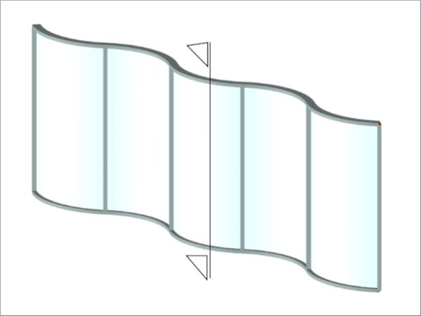
For this theoretical examination, a given situation of room-high IGUs with a defined size and boundary conditions are assumed. For the study of variants different curvatures for the IUGs were specified. Possible curvatures for cold bent glass applications will be analysed. Figure 1 shows the principle of the assumed façade.
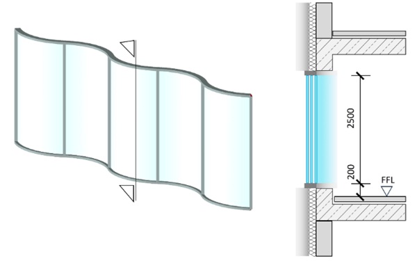
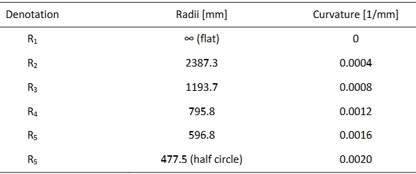
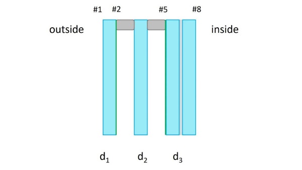
The architectural design of the façade was a corrugated or wavy assembly of the insulated glass units. Alternating IGUs in n-shape and in u-shape position were arranged. The radii and in conjunction the curvatures were varied between a flat IGU and an IGU with the shape of a half cylinder, as shown in Figure 2. All glass elements have the same size with a width or arc length of b = 1500 mm and a height of h = 2500 mm respectively an area of A = 3.75m².
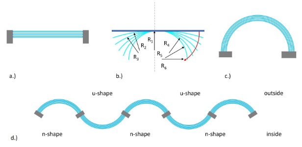
The different radii respectively curvatures between a flat IGU and the shape of a half cylinder (half circle) as shown with b.) in Figure 2 are given in Table 1.
Table 1: Different radii and curvatures of the IGUs.
3. Requirements for the façade according to prEN 19100
The draft prEN 19100 stipulates a clear list of requirements on glass element. The topic of safety against human injuries is described in detail (ONR CEN /TS 19100-4 2023). The two main topics are:
- risk of injury in the event of a collision with glazed element
- risk of falling through the glazing
The assumed IGUs are accessible glass elements with a risk of falling through. For these reasons a laminated safety glass is arranged on the inner side. Due to the consequences of failure or malfunction the IGUs were classified to the consequence class CC-2. In addition to the classification into CC-2 , the glass components of the IGUs were assigned to limit state Scenarios LSS-1. For the unfractured glass state the ultimate limit state ULS and the serviceability state SLS were performed in the analysis. In addition, the fracture limit state with a pendulum impact simulation was carried out (prEN 19100-12023).
4. Assembly of the insulated glass unit (IGU)
Due to building physics demands a triple IGU is defined for the structural analysis. The assembly, as shown in Figure 3 consist of the following elements and are listed in Table 2 from the outside to the inside.
Table 2: Assembly of the IGU.
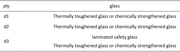
To minimize the Ug-value a sun protection coating on surface #2 and thermal protection coating on surface #5, as displayed in Figure 3, was arranged. With this assembly a Ug-value less than 1.0 W/m²K can be achieved.
The concept of the minimis ation of the thickness of the glass is based on the advantage of higher stiffness of the glass plies in a curved state. The beneficial acting internal membrane forces in a bent glass can be activated.
Due to the before described safety demands a laminated safety glass is arranged on the inner accessible side of the IGU. To reduce the stresses in the laminated glass element due to bending, curving by the bending process during the lamination process was assumed.
The past concept to produce curved IGUs was the production of the curved glass elements in a hot bending process in the first step. During the assembly process metal spacer were approached to the geometry of the glass. With the development of soft spacers, the assembly of the IGUs was much easier. With thin glass we can rethink this concept. A production of stiff spacers can be proposed. The glass fits to the geometry of the spacers. Cold bending is a relatively cheap process in comparison to hot bent glass. The energy demand is much less than hot bent glass.
5. Loads
5.1. Wind
The wind load as an external load was for this specific façade assumed with wind suction ws=1.00 kPa and wind pressure wp=-0.75 kPa.
5.2. Climatic loads
The climatic load as an internal load consists of 3 different components which influences the resulting internal pressure in the cavities.
- Difference in temperature
The difference in temperature as an internal load is influenced by the glass assembly, the indoor and outdoor conditions, and the production conditions. This difference in temperature ∆T is defined as the difference between the mid value of temperature in the cavities and the temperature in the production site in a worst-case combination. These difference in temperature ∆T must be determined for each cavity for summer and winter conditions, as given in Table 3.
With e.g. thermal bridge software tools the thermal distribution through the IGU can be determined.In the case of this analysis, the software tool WinSLT Expert was used. Temperature distribution for load case summer and winter is shown in Figure 4.
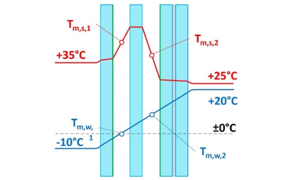
The temperature in the productions site was assumed for summer with Tpr,s = 23.0°C and for winter with Tpr,w =18.0°C. These different temperatures are given in Table 3.
Table 3: Difference in temperature.

- Difference in meteorological air pressure
Difference in meteorological air pressure is given for summer with ∆Pmet,s=-2.0 kPa and for winter with ∆Pmet,w=+4.0 kPa (DIN 18008-1 2020).
- Difference in altitude
For a production site with an altitude of Hpr=350 m and a building site with an altitude of H=450 m a difference in height results with ∆H=+100 m. The building site is 100 m above the production site.
5.3. Barrier loads
The barrier load was given in EN 1991-1-1 with h = 1.0 kN/m for the assumed usage of the building (EN 1991-1-1 2011).
5.4. Pendulum impact
Due to the risk of falling through pendulum impact test the kinetic energy war defined according to DIN 18008-4 with Ekin=EBasis=100Nm (DIN 18008-4 2013).
6. Resistance
For the assumed specific façade, the glass was classified in consequence class CC-2. The design bending strength based on intrinsic glass strength and glass surface pre-stress was determined according prEN 19100-1, as shown in Equation 1 below (prEN 19100-1 2023).

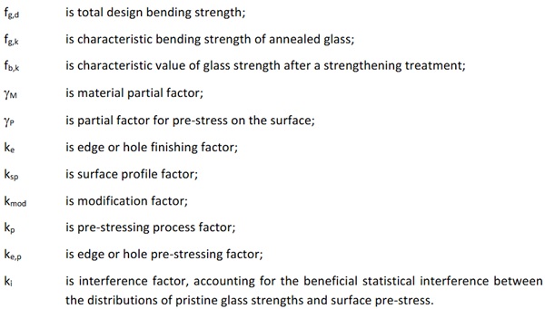
For chemically strengthened glass (d≤2 mm) the design bending stress is given in Eq. (2)
![]()
For thermally toughened glass (d≥2 mm) the design bending stress is given in Eq. (3)
![]()
The size effect λA and λl can be set to a value of 1.0 unless the area of the pane exceeds 18m2.
In case of chemically strengthened glass, the ke,p and kp values can be taken from a transparent and reproducible assessment that complies with all the requirements of EN 1990. For this theoretical study, such assessment couldn't be done. For this reason, these values were set to 1.0 (ONR CEN/ TS 19100-1 2023).
Consequently, a broad experimental test series for the determination of the missing values is needed. Not only for the design in the Ultimate Limit State or Serviceability Limit State there are values missing, also values of short-term strength of chemically strengthened glass for the Fracture Limit State according prEN 19100 are needed.
7. Finite Element Model
Due to the less thickness of the glass plies large displacements resulted in the simulations. Therefore, the geometrically nonlinear behaviour was considered using large deformation theory.
A special effect in insulated glass units is described by the coupling effect. This beneficial acting effect was considered in the finite element models of the whole IGU by using the software module RF-GLAS in simulation package RFEM of the software company Dlubal.
8. Results
For all the insulated glass units with different radii an acting external (wind and barrier loads) and internal loads (climatic loads) an optimization of the glass thickness was elaborated according prEN 19100-1. Limits stipulated in standards and recommendations from the glass industry were considered.
The results of the structural analysis of the ultimate limit state, serviceability limit state and Fracture Limit State are given in the following.
8.1. Ultimate limit state, serviceability limit state
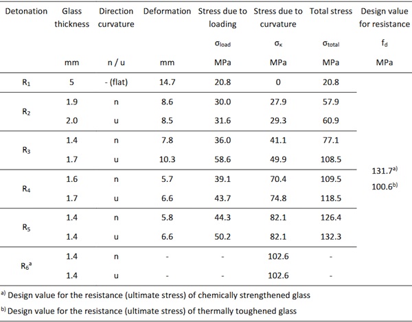
In Table 3 and Table 4 the results of the simulations are shown. The results include deformations, stresses due to loads, stresses due to curvature and ultimate stresses for IGUs made of chemically strengthened glass or thermally toughened glass. Furthermore, the results from curved IGUs distinguish whether they are curved inwards - u-shape - or outwards - n-shape. The results for Table 3 are for a glass thickness of 2 mm and in Table 4 the glass thickness varies.
The results of the IGUs in Table 3 show that only for R1 (flat) the maximum permissible deformation exceeded, which is recommended by the glass industry. The flat IGU deforms by 36.1 mm. For curved IGUs the ultimate stress becomes decisive. For IGUs made of thermally toughened glass, the total stress is exceeded from R4 with 124.0 MPa. From R5 the stress due to curvature exceeds the ultimate stress with 117.3 MPa. For chemically strengthened IGUs the total stress is only exceeded from R5 with 157.6 MPa and from R6 the ultimate stress is exceeded by stress due to curvature with 146.6 MPa. Therefore, no calculations were simulated for R6 (half circle). The results from Table 3 are graphically represented in Figure 5.
Table 4: Deformations, arisen stresses and ultimate stresses for a glass thickness of 2 mm for each radius.
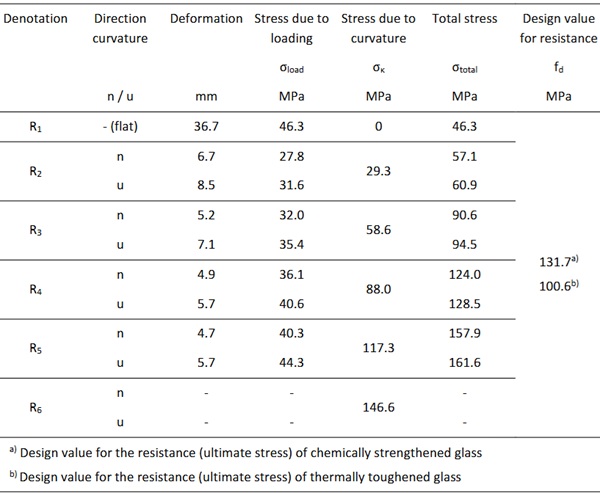
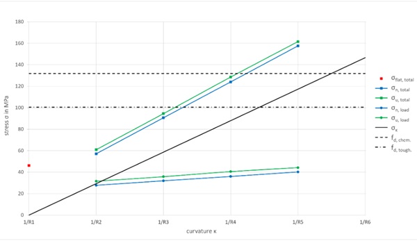
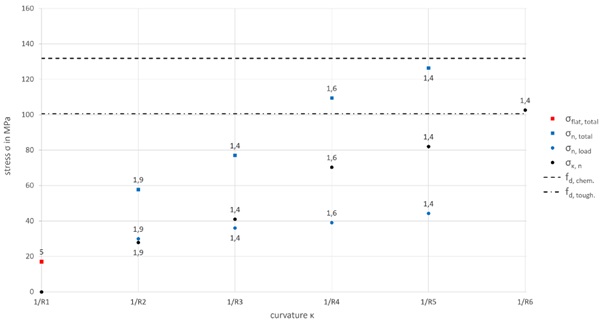
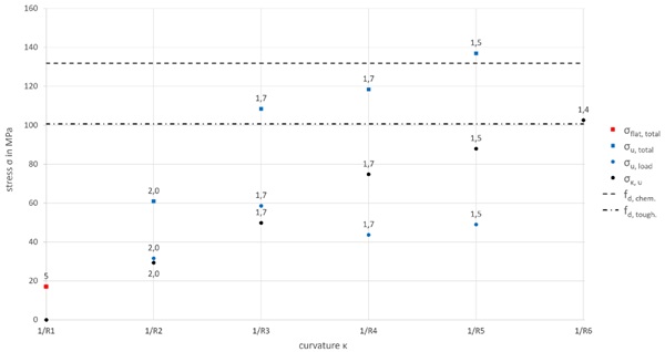
Figure 5, Figure 6 and Figure 7 show the stress due to loading σload, curvature σκ, total stress σtotal and the ultimate stress fd. In general, the results for the flat IGU σflat,total are red, the results for curved IGUs are also highlighted in the index with n, u. Additionally the results for IGUs in n-shape are blue and those for IGU in u-shape are green. Furthermore, Figure 6 and Figure 7 represent the results with different glass thicknesses. The ultimate stresses for chemically strengthened IGUs fd,chem. and thermally toughened IGUs fd, tough. are shown as different dashed lines in black. The stress due to curvature σκ is drawn as a black line. The stresses due to load are marked with a circle. Total stresses are a square.
The results in Table 4 are as mentioned for different glass thicknesses with the flat IGU calculated with a greater thickness of 5 mm to remain below the LSS. Curved glasses were dimensioned as thin as possible. For IGUs made of thermally toughened glass with a glass thickness 1.4 mm with a total stress of 77.1 MPa is simulated. From R3 for u-shape and from R4 the ultimate stress is exceeded. For chemically strengthened IGUs with a glass thickness of 1.4 mm and R5 for n-shape with a total stress of 126.4 MPa is simulated. From R5 for u-shape and from R6 (half circle) the ultimate stress is exceeded. From R6 it is expected that the stress due to loading will continue to increase exceeding the ultimate stress overall. Therefore, R6 was also not simulated. The results of Table 4 are depicted for different glass thicknesses in Figure 6 for n-shape and in Figure 7 for u-shape. The assembly of the flat insulated glass is defined with d1=5 mm, d2=2 mm and d3=10 mm (laminated safety glass 55.2).
Table 5: Deformations, arisen stresses and ultimate stresses for various glass thicknesses for each radius.
8.2. Fracture Limit State
For the verification of the Fracture Limit State a dynamic analysis with the so-called pendulum impact test was performed. The pendulum impact is a highly dynamic process in a very short time which actsless than a second. The verification can be done by experimental tests or with a simulation in a finite element program.
Two different software packages were for the authors able to be used. On the one side the SJ Mepla software tool with an implemented pendulum impact simulation module and on the other side the finite element RFEM with which curved glass can be modelled. The program SJ Mepla has the advantage that it is based transient concept but works only for flat glass elements. The finite element program RFEM has the advantage that curved glass elements can be modelled but it works on a quasi-static concept. The task was to define a link between these two software packages. The link which was found out was the maximum force FP,max with which the pendulum acts on the glass, as described below.
The impact scenario can mechanically be described with the law of conservation of energy which is given in Eq. (4). That means that the potential energy Epot in the position of height of fall is transformed into the kinetic energy Ekin directly before the impact acts. This kinetic energy is transformed in the deformation energy Edef respectively the force of the pendulum FP performs the physical work Wdef. This results in the dependency of the maximum of the force FP with which the pendulum acts on the glass and the deformation of the glass at the location of the impact and the deformation of the rubber of the twin wheels. At a certain time (part of a second) the maximum deformation arises and the force of the pendulum reaches the maximum FP,max.
![]()
The first step was to elaborate with the in the software SJ Mepla implemented pendulum impact module the dependency of the force of the pendulum and the corresponding deformation.
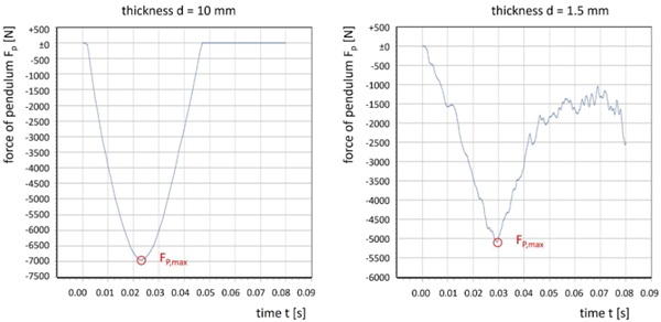
As a result of the simulation for two different glass thicknesses the time-force of pendulum graph is displayed in Figure 8. In the left graph for a glass with a thickness of d=10 mm the time-force relationship with the corresponding maximum force of the pendulum Fp,max= 6944 N is shown. The right graph shows the time-force relationship glass with a thickness of d=1.5 mm as a result with the corresponding maximum force of the pendulum Fp,max=5092 N. The two graphs of the flat glass elements in Figure 8 demonstrate the different behaviours in respect to the vibration behaviour. Thin curved glass has a stiffer behaviour, also the vibration behaviour is that of a thicker glass.
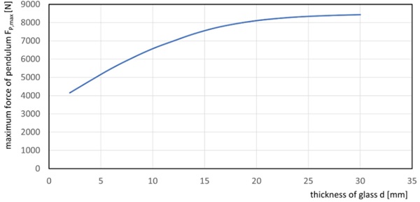
The displacement of the glass with a thickness of d= 0 mm was u=7.6 mm and for the glass with a thickness of d=1.5 mm the displacement was u=35.2 mm which is much higher. It can be summarised that thinner glass has a larger displacement and smaller force of pendulum in comparison to a thicker glass. The thicker the glass ply the smaller is the deformation. This dependency of the force of pendulum an in respect to the thickness of the glass ply is displayed for the specific geometry of the defined IGUs in Figure 9.
The second step was the determination of a fictive glass thickness of the flat glass element in respect on the stiffness of the curved glass ply based on the principle of the same displacement at the mid-point of the impact of the pendulum. Consequently with this concept the maximum of force of the pendulum Fp,max can be adjusted in the RFEM model of the curved IGU.
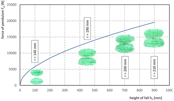
For the finite element model of the curved IGU in RFEM the whole assembly of all glass elements were implemented, for activating the beneficial acting coupling effect. Beside this including of the coupling effect the area if the impact must be adjusted. As shown in Figure 10 the size of the area is depending on the force of pendulum. It can be summarized that the larger the area the lower the arisen stresses, but the dependency to the force of pendulum must be considered.
Figure 10 shows as well a result of pendulum impacts with different hights of fall hF against a concrete wall. The rubber of the pendulum was painted with colour and the imprints of the twin wheels on a paper were for determination of the size of the area of impact analysed. For the simulation in the finite element model based on the elliptical imprints a circle with equivalent area was calculated.
All these influences were considered for the determination of the principal tensile stresses due to the pendulum impact. Beside the acting pendulum all permanent loadings were considered for the determination of the total arisen stresses. The location of the impact was defined as the worst impact location within the zone of impact with 250 mm from the vertical edge and 500 mm above the edge at the bottom of the glass element.
The values for the resistance as a short-term strength is given in e.g. DIN 18008-4 for annealed glass with fd=81.0 MPa, for heat strengthened glass with fd=119.0 MPa and for thermally toughened glass with fd=168.0 MPa. Such values for chemically strengthened glass is missing. DIN EN 12337 stipulates only the characteristic value for the resistance with fk=150.0 MPa (EN 12337).
In internal test series of the research project “Josef Ressel Centre for thin glass technology for structural glass applications” characteristic values for the chemically glass could be determined with values above 200.0 MPa. These results lead to the assumption of a higher short-term strength in comparison to thermally toughened glass. Therefor the short-term strength of chemically strengthened glass was set to 200.0 MPa, shown as ultimate stress in Table 5.
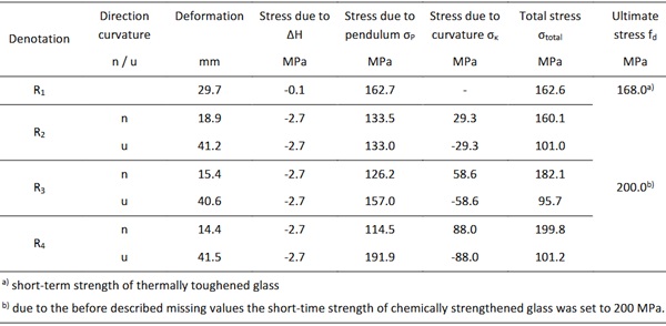
Table 5 shows the results as principal stresses of the simulation of the pendulum impact. The different stress components due to the pendulum impact and the permanent loads - curvature and difference in height – result in a total stress of their load combination.
For the flat IGU (R1) the maximum total stress of the load combination was determined with σtotal=162.6 MPa and below the short-term strength of thermally toughened glass. The result for curved IGUs is a maximum total stress of σtotal=199.8 MPa and below the short-term strength of chemically strengthened glass.
Table 6: Deformations, stresses due to pendulum impact, curvature and climatic load (∆H) for a glass thickness of 2 mm.
9. Environmental impact
Environmental impacts are changes in the natural or built environment, resulting directly from an activity, that can have adverse effects on the air, land, water, fish, and wildlife or the inhabitants of the ecosystem. For a quantification of the environmental impact so called Environmental Product Declaration were defined. An Environmental Product Declaration (EPD) is defined by International Organization for Standardization DIN EN ISO 4025 as a Type III declaration that quantifies environmental information on the life cycle of a product to enable comparisons between products fulfilling the same function. In some of these EPDs life cycle impact assessment results are stipulated per metric tonne of flat glass, in other EPDs the impact is given per square meter for 1 mm glass thickness. The result is for e.g. the global warming potential GWP in kg CO2-Eq. and gives quantified amount of the environmental impact.
For the interpretation of the results in conjunction with the environmental impact a comparison of the weights was done. The flat IGU has a total weight of approx. M=160 kg. In comparison the curved IGU with glass thicknesses of 1.5 mm has a weight of less than M=60 kg. That results in a reduction of the weight of around 60% and in consequence a reduction of the environmental impact of around 60 % too.
The mass is not the only factor that influences the environmental impact. For the assessment of the environmental impact other processes in the production of IGUs such as pre-stressing or laminating must be considered too. All these parts of the production process are mostly remaining the same regardless of the glass thickness and are largely driven by energy requirements and minor influenced by the thickness of glass. When generating energy, it is crucial whether it is produced sustainable by wind-, water or sun power stations or fossil by oil- or gas power stations based. This difference in weight additionally opens for the mounting process a new strategy. The usage of heavy suction devices or big mobile cranes can be rethought about their need. This could lead to additional reduction of environmental impacts.
10. Conclusion and Outlook
The investigation of the flat and curved insulated glass units shows four principal results for this assumed size. The first result is that a flat IGU consists of 2 mm glass plies each the ultimate limit state can be fulfilled, but the displacement is larger than the recommendation given by the industry. This recommendation gives the maximum displacement with which the glass industry guarantee the durability of the edge sealing. The second result is that a flat IGU with the assembly of d1=5 mm, d2=2 mm and d3=10 mm (laminated safety glass 55.2) fulfill the maximum displacement based on the recommendation of the industry but has a low utilization in respect to the ultimate limit state. The third result is that for curved insulated glass the ultimate limit state ULS and the serviceability limit state SLS with a glass thickness less than 2 mm can be verified. The fourth result is that the fracture limit state with the simulation of the pendulum impact can be fulfilled with thin glass.
Further improvements of the chemical pre-stressing technique open the possibility to use thin glass with a thickness less than 2 mm for insulated glass units. Chemically strengthened glass has a high potential for architectural glass applications. But more investigation on chemical strengthening process is needed. One major topic is the increasing of the case depth during ion exchange process. The deeper the ion penetration the better is the performance against surface defects.
References
DIN 18008-1: 2020-05 Glass in Building - Design and construction rules - Part 1: Terms and general bases. Beuth, Berlin (2020)
DIN 18008-4: 2013-07 Glass in Building - Design and construction rules - Part 4: Additional requirements for barrier glazing. Beuth, Berlin (2013)
EN 1991-1- 1: 2011-09 Eurocode 1: Actions on structures - Part 1-1: General actions - Densities, self-weight, imposed loads for buildings (consolidated version) (2011)
ONR CEN /TS 19100-4: 2023-10 Design of glass structures - Part 4: Glass selection relating to the risk of human injury -Guidance for specification (2023)
prEN 19100-1: 2023-02 Design of glass structures - Part 1: Basis of design and materials (2023)
DIN EN 12337-1:2000-11 Glass in building - Chemically strengthened soda lime silicate glass - Part 1: Definition and description. Beuth, Berlin (2000)
Josef Ressel Centre for “Thin Glass Technology for structural Glass applications” Final report (2021)
DIN EN ISO 14025:2011-10 Environmental labels and declarations - Type III environmental declarations - Principles and procedures (2011)