Article Information
- Digital Object Identifier (DOI): 10.47982/cgc.8.442
- This article is part of the Challenging Glass Conference Proceedings, Volume 8, 2022, Belis, Bos & Louter (Eds.)
- Published by Challenging Glass, on behalf of the author(s), at Stichting OpenAccess Platforms
- This article is licensed under a Creative Commons Attribution 4.0 International License (CC BY 4.0)
- Copyright © 2022 with the author(s)
Authors:
- Daniël Wium - MULTI.engineering & Ghent University
- Evert Lataire - Ghent University, Maritime Technology Division, Belgium
- Jan Belis - Ghent University, Magnel-Vandepitte Laboratory, Belgium
Abstract
In recent years, it has become popular for superyacht designs to incorporate large uninterrupted glazed areas in the superstructure. Larger windows increase the amount of natural light that enters the yacht and add to the yacht’s aesthetic appeal and exclusivity. Cruise vessels and other types of passenger ships have seen similar trends. However, window panes are currently isolated from the structural loads within a vessel and their dimensions are restricted by the presence of a frame as aconventional load-bearing structural component. The use of load-bearing glass components presents a solution to this problem as it can also add to the strength of a ship’s structure, thereby reducing the extent of conventional structural materials such as steel or aluminium profiles.
Major challenges exist for the use of glass as a load bearing component in a ships’ structure. Even though a solid scientific background has been established for the structural use of glass in structures on land, a lack in knowledge exists of how the challenges in the marine environment can be addressed. This paper gives an overview of the requirements of a ship structure, and more specifically yacht structures, and describes the challenges associated with using glass as a fully integrated structural component. Further implications for the integration of structural glass in a superyacht structure are also discussed and suggestions for a possible design approach is presented.
1. Introduction
There is a trend in the superyacht industry to increase the amount of glass used in the design of the ship. The use of glass is a way of increasing the spatial experience on board the vessel while also providing striking aesthetics (Verbaas 2012). Superyachts, or ‘yachts’ as they will be referred to in this text, are large private luxury vessels, typically defined as being longer than 24m. Yacht owners seek large uninterrupted glazed areas in their yacht to add to its exclusivity. Larger windows also give passengers a greater sense of the outside world and allow more natural light into the yacht. The transparent barrier allows passengers to enjoy spectacular scenery while being protected from the natural elements (Gizzi & Bennison 2009; Moupagitsoglou 2020; Verbaas 2016b; Vergassola & Boote 2020).
The use of larger windows is also prominent in other types of leisure ships, such as ocean and river cruise ships (Fricke et al. 2014). An example of an expansive glazed area can be found on the ocean cruise ship Iona (P&O cruises) in which a large ‘glass dome’ has been installed (Eckersley O’Callaghan 2019). In river cruise ships there is a trend in creating cabins with glass enclosed balconies to optimize cabin space while providing passengers with panoramic views (Green 2015). Besides the advantages of glass for passengers, it also has a benefit for the shipbuilder. Glass is impervious to corrosion and increasing areas of glazing reduces the amount of necessary costly paintwork (Verbaas 2016b). Although, glass may add significant weight to a vessel due to thicker component requirements in comparison to steel or aluminium components.
However, significant limitations are imposed on the dimensions of uninterrupted glazed areas due to the presence of the structural components of a ship, which impairs the visibility towards the outside and blocks natural light (Boote & Vergassola 2016). The use of load-bearing glass components presents a solution to this problem as it adds to the strength of the ship structure, thereby reducing the necessity for conventional structural materials such as steel or aluminium profiles. However, the brittleness of glass presents considerable challenges for using load-bearing glass in a ship’s structure (Jansen 2014). Even though a solid scientific background has been established for the structural use of glass in constructions on land and design standards are currently under development (Feldmann et al. 2014), there are significant differences between land-based structures and ships. This presents majorobstacles to overcome.
There is a lack of knowledge as to how these challenges can be addressed. In addition, no marine regulations prescribe for applications of glass other than in windows, in which case the glass panes do not contribute to the stiffness of the surrounding structure. Ship structures are built according to the technical standards of a classification society. A common standard which classification societies refer to for the design of yacht windows is ISO 11336 (2012) which only specifies regulations for window panes where their mechanical behaviour is considered independent of the rest of the yacht (Verbaas 2016b). For these reasons, shipbuilders still rely on conventional materials for the structural components of the ship.
This paper aims to present the challenges currently associated with integrating glass into the structure of a yacht and which aspects are important to consider when looking for solutions to increase the transparency of the ship’s structure. Finally, a possible design approach is also presented.
2. Yacht structural design
Integrating structural glass in a yacht requires an understanding of the structural components of a yacht and the loads they must withstand. Yacht structures are typically built according to the guidelines of a classification society which sets technical standards for the ship structure.

The structure of a ship is designed with regards to loads which can be categorised as either ‘global’ or ‘local’. Global loads include bending moments, shear forces and torsions in the overall structure. Theseloads occur due to waves in the ocean and the weight of the vessel. Local loads are considered when designing local areas of the structure and include hydrostatic pressures, ice loads, local cargo loadsand wind pressures.
According to classification societies, global loads need to be considered when the length of a ship exceeds approximately 50m (DNV 2021; Lloyd’s Register 2020). At smaller lengths, it may be sufficientto only consider local loads as stresses due to the global deformation of the ship are less severe thanthat arising from local loads. Typically, ship designers rely on the hull to withstand global loads. However, past research has shown that a superstructure (the structure extending above the upper deck in the hull from side to side, as shown in Figure 1, where most of the glass will typically be located)may add to the longitudinal bending strength of a hull. In yachts, this has become more prevalent in recent years as the extension of superstructures has increased and as scantlings in the hull are reduced to save cost and weight (Boote & Vergassola 2016).
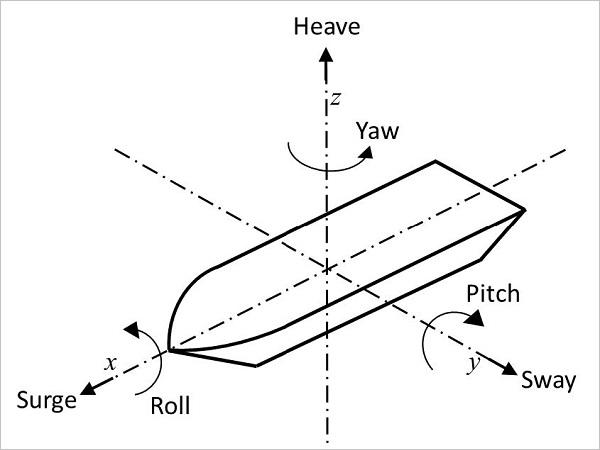
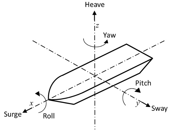
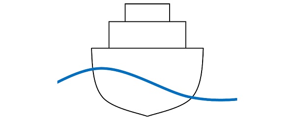
Two main sea conditions can be considered when analysing the deformation of a yacht’s structure: head seas and beam seas. Referring to Figure 2, head seas is when waves are moving in the direction of the longitudinal axis (x-axis) of the ship, while in beams seas waves are moving perpendicular to the longitudinal axis. In head seas, a yacht tends to bend around its transversal axis (y-axis). The most severe bending occurs when the length of a wave is equal to the length of the hull and either the wavecrest or through is in the middle along the length of the hull, as shown in Figure 3. This bending is not as prominent in beam seas, particularly for mono-hull yachts, due to the more uniform distribution of the wave along the length of the hull. In this case there is a larger hydrostatic pressure difference across the width of the hull, as shown in Figure 4. However, due to a low width to depth ratio, global bending around the x-axis can be insignificant.
The self-weight of the ship also results in longitudinal bending of a ship. The bending of the ship is caused by the net vertical force distribution over the length of the ship which is the difference between weight and buoyancy forces. The resultant bending moment and shear force is termed the ‘still water’ bending moment and shear force as it is usually determined in a sea condition without waves.

In both head seas and beam seas, inertial loads may be induced in the structure due to the relative motion of the ship in the waves. In Figure 2, all six degrees of freedom, three linear motions and three rotations are shown. In head seas, a ship heaves and surges, while it heaves and rolls in beam seas. These motions accelerate the ship in the respective directions and cause inertial loads which can beaccentuated in the higher areas of the superstructure.
Waves in the direction between head seas and beam seas, also called quartering seas, are usually neglected during the assessment of mono-hulls as the torsional stresses resulting from this condition are typically smaller in comparison to the stresses from longitudinal bending (due to the width to depth ratio of a yacht). However, for multi-hull ships, vessels with large breadth or big deck openings, torsion due to quartering waves are more significant (Lloyd’s Register 2020).
The magnitudes of local loads are also specified by classification societies. Typically, design pressuresare specified which depends on the location of the structure. For example, the design pressure for external plating would include hydrostatic pressure of still water and waves, and wind loads for areas above the waterline. Deck pressures account for green water (water from large waves), ice and cargo.Internal plating should also be designed to withstand pressure from liquids in tanks.
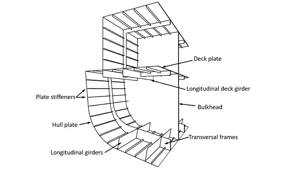
In general, global loads (inducing longitudinal bending of a ship) are resisted by structural components such as plates, plate stiffeners and longitudinal girders. Transversal frames and bulkheads, as well as plates and secondary stiffeners, resist local pressures. In Figure 5, these structural components are illustrated.
During the structural design of yachts, vibration analyses are also performed to check whether vibrations in the structure, originating from excitation sources such as engines, propellers and generators, are below acceptable levels. Yachts designers are motivated to keep vibrations in the structure to a minimum to reduce noise levels inside the yacht and improve the comfort of passengers (Boote et al. 2017; Vergassola & Boote 2020).
In the yacht industry, it is customary to fabricate the structure of the hull from steel and the superstructure from aluminium. This is mainly done to reduce the overall weight of the vessel, while ensuring that maintenance on the hull can be more readily performed. Welding steel requires less skills than welding aluminium. Aluminium also results in lower stresses in the superstructure during bending around the y-axis in comparison to a steel superstructure, due to the difference in Young’s modulus.
The use of glass in yachts is currently limited to applications which do not contribute to the overall strength of the ship. For example, glass in window panes, balustrades, deck hatches, doors and stairs. For these applications either thermally pre-stressed or chemically pre-stressed glass is used. Chemically strengthened glass is more often preferred for glass in windows as it has a better optical quality. In the next section, the role of windows in the design of a yacht’s structure will be further discussed.
3. Structural implications of large windows in yachts
Yacht designers are faced with an array of challenges when pushing the boundaries of window dimensions. These challenges arise due to the structural issues associated with large openings in the ship structure.
The high brittleness and significant scatter on the strength of glass makes it not an evident choice as a load-bearing material in ships. For this reason, shipbuilders usually ensure that forces are not transferred from the ship’s structure onto the glass panes of windows. This is typically done through the use of a flexible adhesive bonding between the glass and the metal window frame (ISO 2020). This is taken into account during the design of ship windows and the analysis of a ship’s strength during which the contribution of window panes to the stiffness of the structure is disregarded (ISO 2012; Wiegard et al. 2018).
As a result, windows are considered as large holes in the structure of a ship. Additionally, to necessitate the large openings in the structure, scantlings are reduced on the side of superstructures to increase transparency. These scantlings are often optimized against allowable stresses and buckling. Moreover, plates and beams in the hull are also minimised to reduce the overall cost of the vessel (Boote & Vergassola 2016). If glazed areas in a yacht design are to be increased, it may result in buckling problems and the reduction of the longitudinal strength of the vessel. In particular, large openings in plates can greatly reduce their shear and axial stiffness (Fricke & Gerlach 2015). This can especially lead to severe consequences in yachts where the superstructure is often fabricated with aluminium alloy (Vergassola & Boote 2020).
Therefore, allowing glass to add to the stiffness of a ship’s structure and take on some of the loads within the ship would offer a solution to these problems and allow designers to greatly increase the size of glazed areas. However, to do so, a number of challenges first need to be overcome. In the next section, these challenges are described in more detail.
4. Challenges for structural glass in ships
The differences between marine structures and land-based structures, as well as the differences in their environments, pose significant challenges for structural glass in ships. These differences pose obstacles for the transfer of structural glass technologies from land to sea. In the following sections, these differences are highlighted and it is explained why they pose challenges for glass structures.
4.1. Ship structural requirements
In general, the deformations of ship structures are of larger magnitudes than that of buildings. A combination of loads can also be present which would not occur in structures on land. A ship is subject to wave motions which induce accelerations and dynamic loads on its structure (Moupagitsoglou 2020). Dynamic loading is currently not assessed in global load analyses of yachts, however, this is an important consideration for glass components. Besides this, accelerations can occur due to movements such as yaw, pitch and roll (Figure 2), and are imposed on the entire ship structure.
Exceptional wind loads can also be encountered and in severe weather conditions, green water can flow onto the decks and waves impact the sides of the ship (Verbaas 2016a). Some buildings are designed to withstand wind loads of similar magnitudes and high accelerations during earthquakes, but ships experience these loads simultaneously. These conditions result in larger deformations in ships, which is further aggravated by the fact that modern ships are constructed out of thin metal plates, making them inherently more flexible than buildings (Verbaas, 2016a).
The deformation of a ship poses difficulties for the way in which it is connected to the rest of the ship’s structure. Glass’s inability to deform plastically makes it particularly vulnerable to stress concentrations. Therefore, the load introduction points and connections between the glass structure and the rest of the ship must be taken into careful consideration (Katsivalis et al. 2018). Deformation of the structure due to global and local loads, and thermal expansions should be taken into account. In Section 5, current connection concepts which have the potential of addressing these issues are discussed.
4.2. Weather conditions
It has been shown that certain components of glass structures are adversely affected by certain environmental factors, particularly extreme weather conditions. This is specifically the case for the adhesive materials used in bonded connections in glass structures and the polymer interlayer material of laminated glass panels, which can deteriorate under long-term exposure to high temperatures, humidity and UV-radiation.
Even though glass structures have been proven to withstand a wide range of weather conditions, this has mostly been done on land and for the conditions of their local environment. Ships may experience a much more diverse and extreme set of weather conditions in comparison with land-based structures. This is due to the fact that ships are free to travel to wherever they are suitable to sail and are, therefore, subject to different climates. There is currently little knowledge on how glass structures will behave when exposed to a very wide range of possible weather conditions, especially under the structural requirements of a ship. Besides this, there is also a lack of data on the durability of adhesives in glass structures, especially in corrosive environments such as at sea (Dispersyn & Belis 2016; Pereira et al. 2013).
4.3. Safety requirements
The main factor which sets the safety requirements of ships apart from the requirements of buildings, is that ships are surrounded by water. In most cases, buildings offer people the option of evacuating onto the surrounding land in case of emergencies. However, this is not possible on a ship and the possibilities to evacuate are very limited. Evacuating can even be considered hazardous in some circumstances, such as during a storm or while sailing close to a treacherous shoreline. For this reason, ships themselves are required to offer safety during incidents which can cause harm (Moupagitsoglou 2020; Verbaas 2016a).
Due to the above, safety requirements for windows in ships differ to those in buildings in certain cases. As Verbaas (2016a) explains, this is evident when comparing a small window of a building near the ground level with a small window of a ship near the waterline. In case the building window breaks, the risk of injury is generally low. Unless the distance from the ground to the window is such that shards of glass will fall on people, there is still a low chance of people being injured by the falling glass. Compare this with a window near the waterline of a ship. A fractured window runs the risk of allowing water to enter the ship, either by leaking or breaking completely, which can negatively affect the stability of the ship. Replacing a broken window can be time consuming and may only be possible once a ship returns from its voyage. Therefore, even after fracturing, it is preferable for a window to offer a degree of watertightness and weathertightness.
5. Considerations for the integration of structural glass
Four aspects which should be considered when integrating structural glass into the structure of a yachtare discussed in this section. Each of these aspects play an important role in the design of ships with integrated glass structures and are also highly dependent on one another in this regard. These aspects are indicated in Figure 6.
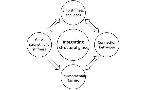
5.1. Ship stiffness and loads
Currently, glass in ship windows are designed to withstand local loads acting on the glass panes. However, the mechanical behaviour of glass within windows are independent of that of the adjacentmetal structure. For this reason, structural issues arise when the dimensions of windows are enlarged to the point where the remaining aluminium or steel structure provides insufficient stiffness in terms of resisting the global loads within the ship.
An alternative is to integrate glass in such a way to allow it to contribute to the ability of the ship to resist both global and local loads to further increase glazed areas. In this case, new requirements are imposed on the connections between the glass and metal components as well as on the strength of the glass components, these requirements can greatly differ from the current requirements of glass in windows, as are further discussed in Section 5.2 and 5.3, respectively.
The point at which these requirements change, can at present only be determined through a parametric study of the entire ship structure as a number of variables come into play. These variables include the location of the glazed area, the size of the glazed area, the parameters of the ship (e .g. length, beam, height and internal structure) and the loads acting on the vessel (as explained in Section 2). In Section 6.1, a proposed design methodology is presented to determine the relationship between these variables.
5.2. Connection behaviour
The ability of a glass structure to resist loads is closely related to, amongst other things, its connection systems to other parts of the structures (Centelles et al. 2019). With regards to land-based glass structures, significant engineering work is dedicated to the connections in such structures, as they are considered to be critical components of the underlying structure (Dispersyn & Belis 2016; Silvestru et al. 2019). For connections between glass components and the rest of a yacht structure, the behaviour of those connections can determine the extent to which forces are transferred between the structural components and they can also influence the stresses in the glass components at the connection interface.
The existence of microscopic flaws on glass surfaces, makes them sensitive to stress concentrationswhich can lead to the propagation of cracks. For this reason, glass connections in yachts will berequired to minimise the stress concentrations while allowing glass components to contribute to the stiffness of the yacht. Currently, the adhesive bonding used to connect window panes to the structure of a ship partly satisfies this requirement by allowing relative movement between the glass and the metal substrates, thereby reducing stresses (Moupagitsoglou 2020). This is frequently done using a flexible polyurethane adhesive with a low stiffness. This could make them unsuitable for resisting the global loads within the ship’s structure.
However, there are other types of adhesives that may be more suitable for such an application. Furthermore, adhesive bonding has many advantages over mechanical connections, making them a preferable choice as a connection method (Dispersyn & Belis 2016; Machalická & Eliášová 2017; Van Lancker et al. 2016). Adhesives also have an aesthetic appeal since they do not have protruding elements and can offer a smoother transition between structural components (Centelles et al. 2019; Katsivalis et al. 2018). The latter will be beneficial to yachts where visual quality is paramount (Moupagitsoglou 2020). A drawback of adhesives are that their mechanical performance can be negatively affected by certain environmental factors. This is further elaborated on in Section 5.4.
Structural silicones have most often been used in bonded glazing in the building industry as they have proven to perform well in areas of high wind load and extreme temperatures (Van Lancker et al. 2018). However, silicone-based adhesives can cause contamination of metal bonding surfaces (Moupagitsoglou 2020). Epoxies and acrylates are in general more stiff and stronger than silicones and polyurethanes, while silicones and polyurethanes are more flexible and resistant to weather factors.
The stiffer adhesives allow higher shear loads to be transferred, while the more flexible adhesives better distribute stresses Belis et al. 2011; Centelles et al. 2019; Dispersyn & Belis 2016). When looking at suitable adhesive products for structural glass connections in ships, epoxy and acrylate adhesives present more favourable structural capabilities, but their low ductility and the fact that they are generally applied in thinner layers, leaves less room for relative movement between substrates. This may lead to stress concentrations in glass.
A possible solution is the use of a stiff steel or aluminium edge profile adhesively bonded along the edge of a structural glass member, e.g. edge of a laminated glass panel. This metal profile is then bolted to the structure of the yacht, possibly incorporating dampers and specific degrees of freedom. The ability of the adhesive to evenly distribute loads will reduce stress concentrations in the glass while local metallic mechanical connections can be used to accommodate required degrees of freedom and also account for geometric tolerances.
5.3. Glass strength and stiffness
The strength and stiffness of structural glass components in a yacht are also closely related to the global behaviour of the ship structure. As an initial design requirement, the stiffness of the glass components need to be such that the global behaviour of the ship meets the requirements of classification societies, in terms of the allowable stresses in the metal components. However, care should be taken not to overdesign the glass components by giving them too much stiffness, as this will result in higher local stresses in the glass, which could have been accommodated by the metal components. Vibration and noise inside the yacht should also be considered during the structuraldesign of large glass panels. It has been shown that the vibration of window panes can significantly contribute to noise levels in a cabin when resonating with excitation sources on the ship (Boote et al. 2017).
In the case of glass panels located in lower areas of the superstructure and hull, a degree of water and weather tightness should be provided after breaking of the glass panel. This can be achieved through the use of laminated glass panels where the interlayer can keep broken glass pieces attached to the interlayer, thereby creating a barrier even after structural failure of the component. Laminated glass can also offer progressive failure and maintain a degree of rigidity after failure of some of the glass sheets in the laminate. However, further research is required to determine which interlayer materials will provide suitable strength and stiffness.
5.4. Environmental factors
Environmental factors can have a great influence on the stiffness of laminated glass components and adhesive materials. Laminated glass panels behaves viscoelastically, while exposure to high levels of humidity, salt concentration and UV-radiation may also have a detrimental effect on the interlayer byreducing the bonding strength between glass sheets (Pereira et al. 2013; Ranocchiai et al. 2018). These environmental factors can also negatively affect the mechanical performance of adhesive (Katsivalis et al. 2020).
Under prolonged exposure to these environmental parameters, it has been found that the mechanical properties of adhesives deteriorate (Pereira et al. 2013; Van Lancker et al. 2016). These environmental parameters can be amplified at sea where high levels of temperature, humidity, salt concentration and UV-radiation can be expected. Sometimes, all at once. Therefore, environmental factors should be considered during all aspects of the design of integrated glass components, both on the global level and the component level.
6. Proposed design approach
The design of integrated glass components can be approached on two levels: a consideration of the overall strength of a yacht (global analysis) and a more detailed assessment of individual components (local analysis).
6.1. Global analysis
As discussed in Section 5.1, increasing the size of glazed areas to the point where glass is required to become a fully effective component of the overall stiffness of a yacht requires a parametric study of the structure to account for the various variables involved. At present, a finite element (FE) analysis is the most capable method of performing such a study. Performing a global FE analyses is a common method of assessing the capability of a ship to resist global loads. However, creating an FE model of an entire ship structure is time consuming and complex. Therefore, simplifications are required for boththe metal and glass components within the model.
Laminated glass components can be simplified within the global FE model by representing such components as monolithic glass with effective thicknesses (Galuppi & Royer-Carfagni 2012). The glass-metal connections will also require simplification. It is proposed to implement connections in the FE model which can simulate the mechanical behaviour of more detailed design concepts. Once suitable parameters for such connections have been found, detailed concepts can be developed during the local analysis as discussed in Section 6.2.
At present, the required strength and stiffness of structural glass components and glass-metal connections remain, to an extent, unknown. Therefore, an iterative process is required to determine suitable strength and stiffness parameters. This iteration process will be specific to the area of the yacht where structural glass is to be implemented, but needs to be repeated for other locations in the yacht as it will influence the global behaviour of the ship.
In Figure 7, an outline for such an iteration process is given where the stiffness of the adhesive material used in the glass-metal connections and the stiffness of the glass components are varied iteratively. The stresses in glass and metal components are then monitored along with the shear strain of the adhesive material. Suitable parameters for the adhesive and glass components can then be found for allowable stresses and shear strains.
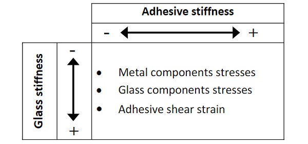
The criteria for the allowable stresses in the glass need to consider both the strength resistance in an intact (unfractured) condition and a scenario where glass sheets in laminated glass start to fracture. For such a scenario a safety philosophy needs to be defined which considers the location of the glass in the yacht and prescribes the minimum safety requirements for the stability of the yacht and the safety of the passengers on board.
6.2. Local analysis
The results of the global analysis can be used to design the individual components of the integrated glass structure. Here, more detailed FE models are created with loading and boundary conditions which are derived from the global FE model. In the case of laminated glass components, solid element models with elements through the thickness of the laminate can be created to capture the response of the glass and the interlayer material more accurately. Further investigation on the fracture pattern of such glass components can also be performed. Effective thickness methods can be used to determine the thickness of the laminate glass layers based on the monolithic thicknesses used in the global FE model. Similarly, the parameters that were found during the global analysis can be used to choose existing adhesive products for a more detailed analysis.
Since environmental factors affect the mechanical behaviour of adhesive materials, experimental work is needed to support the detailed FE analyses. Artificial ageing experiments are typically used to estimate the degradation of adhesive materials, the properties of which can be included in the detailed FE models.
Once a local analysis has been performed, a validation of the global FE model is required to verify the stiffness parameters of the glass components and the adhesive connections.
7. Conclusion
Integrating structural glass into the structure of a yacht requires an understanding of the requirements of the marine environment and the capabilities of glass. However, there remains a lack of knowledge as to how structural glass components will perform within a ship’s structure. Further research is required to identify how current structural glass technologies, which have proven to offer suitable solutions for glass structures on land, can be further developed to overcome the challenges of the marine environment.
Acknowledgements
The contribution by Oceanco and MULTI.engineering for providing project examples and by Flanders Innovation and Entrepreneurship (Agentschap Innoveren en Ondernemen) for financial support under Baekeland Mandate HBC.2021.0194 is highly appreciated.
References
Belis, J., Van Hulle, A., Out, B., Bos, F., Callewaert, D., & Poulis, H. (2011). Broad screening of adhesives for glass-metal bonds. Proceedings of Glass Performance Days 2011, April, 286–289. https://biblio.ugent.be/publication/1579222
Boote, D., Pais, T., Vergassola, G., Tonelli, A., & Gragnani, L. (2017). On the damping coefficient of laminated glass for yacht industry. International Shipbuilding Progress, 64(1–2), 25–40. https://doi.org/10.3233/ISP-170131
Boote, D., & Vergassola, G. (2016). Local and global analysis of large motoryacht superstructure. Proceedings of the 24th International HISWA Symposium on Yacht Design and Yacht Construction.
Centelles, X., Castro, J. R., & Cabeza, L. F. (2019). Experimental results of mechanical, adhesive, and laminated connectionsfor laminated glass elements – A review. Engineering Structures, 180, 192–204. https://doi.org/10.1016/j.engstruct.2018.11.029
Dispersyn, J., & Belis, J. (2016). Numerical research on stiff adhesive point-fixings between glass and metal under uniaxial load. Glass Structures and Engineering, 1(1), 115–130. https://doi.org/10.1007/s40940-016-0009-2
DNV. (2021). Rules for Classification Ships - Part 3 Hull, Chapter 4 Loads (Issue July).
Eckersley O’Callaghan. (2019). Iona Skydome. https://www.eocengineers.com/en/projects/iona-skydome-370
Feldmann, M., Kasper, R., Abeln, B., Cruz, P., Belis, J., Beyer, J., Colvin, J., Ensslen, F., Eliasova, M., Galuppi, L., Geßler, A., Grenier, C., Haese, A., Hoegner, H., Kruijs, R., Langosch, K., Louter, C., Manara, G., Morgan, T., ... Zarnic, R. (2014). Guidance for European Structural Design of Glass Components (Issue February 2016). https://doi.org/10.2788/5523
Fricke, W., & Gerlach, B. (2015). Effect of large openings without and with windows on the shear stiffness of side walls in passenger ships. Ships and Offshore Structures, 10(3), 256–271. https://doi.org/10.1080/17445302.2014.912048
Fricke, W., Gerlach, B., & Guiard, M. (2014). Experimental and numerical investigation on the load carrying behavior of large ship windows. Proceedings of the 33rd International Conference on Offshore Mechanics and Arctic Engineering -OMAE14, 4A. https://doi.org/10.1115/OMAE2014-23803
Galuppi, L., & Royer-Carfagni, G. (2012). The effective thickness of laminated glass plates. Journal of Mechanics of Materials and Structures, 7(4), 375–400. https://doi.org/10.2140/jomms.2012.7.375
Gizzi, V., & Bennison, S. J. (2009). New Marine Glazing Developments. Glass Performance Days 2009, 149–151. http://www.glassfiles.com/library/article.php?id=1392
Green, M. (2015). River Cruise Ship Design’s Impact on the Industry. TravelAge West. https://www.travelagewest.com/Travel/River-Cruise/River-Cruise-Ship-Design-s-Impact-on-the-Industry
International Organisation for Standardizarion. (2012). Large yachts — Strength, weathertightness and watertightness of glazed openings (ISO 11336-1). In International Organisation for Standardizarion.
International Organisation for Standardizarion. (2020). Large yachts — Strength, weathertightness and watertightness of glazed openings (ISO 11336-2). In International Organisation for Standardizarion.
Jansen, K. M. (2014). Glass As a Load Bearing Material in Yacht Structures. Proceedings of the 23rd International HISWA Symposium on Yacht Design and Yacht Construction.
Katsivalis, I., Thomsen, O. T., Feih, S., & Achintha, M. (2018). Strength evaluation and failure prediction of bolted and adhesive glass/steel joints. Glass Structures and Engineering, 3(2), 183–196. https://doi.org/10.1007/s40940-018-0070-0
Katsivalis, I., Thybo, O., Feih, S., & Achintha, M. (2020). Effect of elevated temperatures and humidity on glass/steel adhesive joints. International Journal of Adhesion and Adhesives, 102(July), 102691. https://doi.org/10.1016/j.ijadhadh.2020.102691
Lloyd’s Register. (2020). Rules and Regulations for the Classification of Special Service Craft. July. http://www.lr.org
Machalická, K., & Eliášová, M. (2017). Adhesive joints in glass structures: effects of various materials in the connection, thickness of the adhesive layer, and ageing. International Journal of Adhesion and Adhesives, 72, 10–22. https://doi.org/10.1016/j.ijadhadh.2016.09.007
Moupagitsoglou, K. (2020). Structural Glass in Superyacht Applications: Overcoming Challenges, Design Standards and Analysis Methods. Proceedings of Challenging Glass 7 Conference on Architectural and Structural Applications of Glass.
Pereira, A. M., Reis, P. N. B., Ferreira, J. A. M., & Antunes, F. V. (2013). Effect of saline environment on mechanical properties of adhesive joints. International Journal of Adhesion and Adhesives, 47, 99–104. https://doi.org/10.1016/j.ijadhadh.2013.08.002
Ranocchiai, G., Sciurpi, F., & Fagone, M. (2018). Laminated glass beams subjected to artificial solar radiation. Challenging Glass 6: Conference on Architectural and Structural Applications of Glass, CGC 2018 - Proceedings, 447–452. https://doi.org/10.7480/cgc.6.2167
Silvestru, V. A., Englhardt, O., & Schneider, J. (2019). Linear adhesive connections at the edge of laminated glass panes: an experimental study under tensile, compressive and shear loading. Glass Structures and Engineering, 4(1), 45–68. https://doi.org/10.1007/s40940-018-0080-y
Van Lancker, B., De Corte, W., & Belis, J. (2018). Mechanical properties of continuous adhesive glass-steel connections under monotonic and cyclic loading. Glass Structures and Engineering, 3(2), 197–211. https://doi.org/10.1007/s40940-018-0072-y
Van Lancker, B., Dispersyn, J., De Corte, W., Belis, J., Lancker, B. Van, Dispersyn, J., Corte, W. De, & Belis, J. (2016). Durability of adhesive glass-metal connections for structural applications. Engineering Structures, 126, 237–251. https://doi.org/10.1016/j.engstruct.2016.07.024
Verbaas, F. (2012). Use of Glass and the Regulations. Proceedings of the 22nd International HISWA Symposium on Yacht Design and Yacht Construction.
Verbaas, F. (2016a). Foundations for a code for Maritime Structural Design of Glass Components. Proceedings of the 24th International HISWA Symposium on Yacht Design and Yacht Construction.
Verbaas, F. (2016b). From Simple Window to Structural Material: Application of Glass on Board, an Update (Part 1). Schip En Werf de Zee, February, 268–273.
Vergassola, G., & Boote, D. (2020). A simplified approach to the dynamic effective thickness of laminated glass for ships and passenger yachts. International Journal on Interactive Design and Manufacturing, 14(1), 123–135. https://doi.org/10.1007/s12008-019-00614-2
Wiegard, B., Ehlers, S., Klapp, O., & Schneider, B. (2018). Bonded window panes in strength analysis of ship structures. Ship Technology Research, 65(2), 102–121. https://doi.org/10.1080/09377255.2018.1459066


