Author: F. A. Veer
Source: Glass Structures & Engineering volume 9, 77–98, (2024)
DOI: https://doi.org/10.1007/s40940-024-00251-6
Abstract
The four point bending test is one of the most commonly used and standardised tests to determine the mechanical properties of materials. For its use on float glass there are both the ASTM C158-02R17 and European EN 1288-3:2001 standards. However when testing float glass the results tend be a statistical muddle. This impacts the reliability of the design strength of float glass determined using four point bending tests. In an attempt to resolve this problem a series of four point bending tests were conducted which were designed to be more systematic than those previously reported in the literature and which use newly developed digital microscopy techniques for pre- and post-test analysis. By systematically testing, the test results can be divided into different groups based on air side, Sn side and source of failure, allowing the data to be divided into clear and separate statistical groups. Secondly the results can potentially be used to validate the lower bound glass strength theory proposed by Ballarini et al. (J Eng Mech 142(12):04016100, 2016). The glass specimens were industrially cut, ground, chamfered and flat polished on the long sides. Specimens were checked using advanced digital microscopy before and after testing.
The results suggest that uni-modal Weibull behaviour only applies above a critical failure stress. Failures at stresses below this critical failure stress as a group have a separate and steeper Weibull slope. This supports Ballarini’s theory for a lower bound failure strength although there are important differences between the air side and Sn side of the specimens which this theory does not currently allow for. These differences seem to be inherent to the differences between the glass and the Sn sides. The results also show that the strength of cut, ground, chamfered and flat polished glass can be high but that inconsistency in process control and the irregular occurrence of surface failures are the main causes for the statistical spread. Digital microscopy can reliably measure the quality of the various surfaces and intersections of surfaces of a glass specimen but there is no absolute relation between the size of a detected defect and the probability that this defect actually leads to failure.
1 Introduction
The four point bending test is one of the standard test methods to determine the strength of materials. For glass it is standardised in for instance the ASTM C158-02R17 and European EN 1288-3:2001 standards. Practical guidelines for the test are given by Blank et al. (1994). This has been recently updated for thin glass and non-linear elastic deformation by Peters et al. (2023).
The main problem with using the four point bending test to determine the strength of glass is interpreting the resulting data. In glass the scatter in bending strength is significant, within a single test series the value for the maximum can be two or three times the value of the minimum. This is usually solved by using the uni-modal Weibull distribution as a statistical model, Weibull (1939). This model is mathematically based on the weakest link principle and should thus be appropriate to describe the strength distribution of a brittle material failing by the principles of Linear Elastic Fracture Mechanics (LEFM). Using this distribution to describe the strength of glass was validated by Bartenev (1960) and Kneser (1963). It should be noted however that these results were not obtained on float glass, which was not invented or available then. A good review of the statistical problems of glass strength is given by Pisano and Carfagni (2015, 2017).
More recently several authors have found problems in using the Weibull distribution to describe the results of tests on float glass, Kinsella et al. (2018, 2020), Veer and Rodichev (2011). It is clear that part of the problem lies in the differences of the edge finish between specimens making it difficult to compare the results of different test series, Bukieda et al. (2020). Also, there is the problem that failure can originate at the processed edge or on the air or Sn side surface and potentially from interior defects. Interior defects exist as shown by Molnár and Bojtár (2013). The occurrence of internal defects is highly variable between manufacturers. In the authors personal experience in testing float glass these defects are rare. The nature of the stress field in four point bending makes it unlikely that an interior defect leads to failure, unless it is close to the surface under tensile stress or has been opened up by edge processing. Pisano and Carfagni (2015) have shown that there is a strength difference between Sn and air sides. There is extensive research on the effect of cutting processes on the edge strength of glass, Bukieda et al. (2022) and Seel et al. (2023).
This shows that the differences in edge processing result in differences in edge strength, but that for a single group of similarly processed glass specimens of the same glass and thickness the group is consistent. There is a considerable effect of Sn side versus air side on the surface strength, Krohn et al. (2002). This is attributed to larger defects on the Sn side resulting from contact with the ceramic rollers in the annealing lehr. The parameters governing edge strength, including air and Sn side, have been investigated extensively by Seel et. al (2021, 2023). It is clear that better results are obtained if the glass is cut on the air side but the difference between scoring on the air or Sn side in this research are small compared to the effects of the other parameters investigated. In the bulk of the literature the source of failure of individual specimens or side of failure is usually not mentioned, a notable exception is Müller-Braun et al. (2020). So potentially most of the published data could be a mixture of two or more statistically separate groups in each publication.
However part of the problem may lie in a fundamental problem with the Weibull statistic itself and the possible existence of a lower bound failure strength of glass as proposed by Ballarini et al. (2016). Recent critical experimental evidence by Pan et al. (2024) shows that indentation damage on annealed float glass only decreases the bending strength to a certain minimum value. Increasing the damage did not result in a further decrease in strength. This supports the concept of a lower bound failure strength or a maximum damage limit for float glass.
This lower bound failure strength would cause a downward slope of the Weibull curve in the low strength region which cannot be described by the uni-modal Weibull function itself. Although it is tempting to use a bi-modal Weibull function to fit this type of data, this by definition assumes that the data is part of a single statistical group and is thus based on a single physical failure mechanism. The lower bound failure strength model of Ballarini however implies that below a certain failure strength the mechanics of failure change and that there is thus not a single statistical group. So a bi-modal Weibull function might well fit the data and the use of it could be valid as a predictive model (on the data set used), but as different physical mechanisms are controlling the lower and upper strength data sets physically, it is not correct to use a single mathematical description. Moreover this would not have a general predictive value for different types and qualities of edge finishing.
To check the validity of this lower bound failure strength theory, a set of float glass specimens with high quality edge finish were ordered. Enough specimens were ordered that series of 50 specimens were available for both air and Sn side. These were tested systematically to look for possible effects of air side and Sn side as well as for the effects of differences in edge finishing. Digital microscopy was used to characterize the edge and surface quality prior to testing as well as the fracture pattern and fracture surfaces post-testing. This was done using appropriate magnification and lighting for each surface and defect pattern. The aim being to correlate surface quality, edge quality and fracture pattern to out of plane bending strength. This while having enough data points so that some low strength failures are likely.
2 Material used
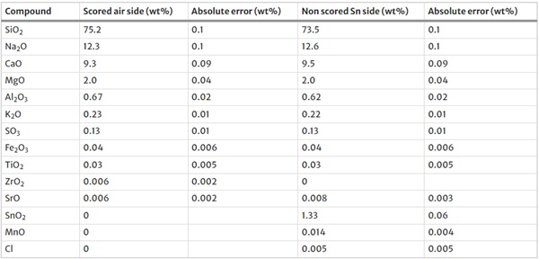
For these tests normal 6 mm thick annealed float glass was used. The composition of both surfaces was measured using the X-Ray Fluorescence (XRF) technique. A Panalytical Axios Max WD-XRF spectrometer was used and data evaluation was done with SuperQ5.0i/Omnian software. The chemical composition is given in Table 1. All glass used was cut as strips 1 m long from the corner of a single jumbo plate, cut on a single industrial cutting table with the same settings for all strips and then edge processed on the same edging machine using the same settings for all strips. The length direction of all specimens was in the length direction of the jumbo plate. Scoring was done on the air side using a Tungsten carbide roller. The cut glass was arrised, ground and polished on the long sides of these strips using standard industrial equipment, lubricants and polishing agents. All edge processing was done on the same machine using the same settings. As it was not recorded what the location of the strips in the jumbo plate was, any effect of the location within the jumbo plate cannot be determined.
Table 1 Chemical composition as measured by XRF - Full size table
Upon arrival, all strips were laid upon a table with the scored side, visible from the non-processed short edges, upwards. Each strip was divided into 4 equal lengths of 250 mm and marked with a waterproof permanent marker on the scored (air) side as A1 to A4 for the first strip and this was continued to X1 to X4 for the last strip. The strips were then manually cut into four equal lengths using a lubricated Tungsten carbide wheel glass cutter. Specimens A1–A4 thus being from a single original strip and having been processed by the same machine at the same time, forming a statistical sub-group.
To ensure that there was no residual stress, 10% of specimens were measured using a SCALP 5 device under good measuring conditions. No residual stress was detected which in practice means that any residual stress is smaller than 5 MPa, which is the resolution of the SCALP 5.
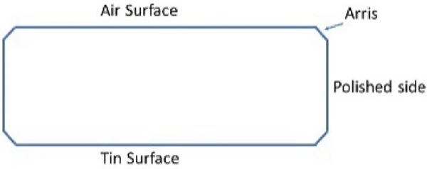
Each glass specimen is composed of several surfaces and their intersections. These are shown in Fig. 1.
Specimens were examined using a Keyence VHX 7000 microscope to determine the condition of the air and Sn side surfaces, the quality of the arris and the polished sides, 2d and 3d photo’s being made. It should be noted that the Keyence VHX 7000 digital microscope has a travelling range of some 50 mm depending on the magnification. At the high magnifications required, at most 1 mm of continuous 3D image can be made resulting in a 100 Mb image. Thus the entire length of each specimen could not be recorded before testing and only representative sections could be inspected. The lens used has a magnification from 40 × to 500 ×. Depending on the magnification and the contrast defects as small as 2 µm can be identified. The outline of larger defects can be determined with similar accuracy, but depth measurement is more difficult and reliability is difficult to assess.
Table 2 summarizes what was observed. The term defect is used in the context that it is a geometrical disturbance in the structure that will cause a stress concentration.
Table 2 Summary of damage at different locations using the microscope - Full size table

The air and Sn surfaces were flat and almost featureless. Figure 2 is a typical example. Visible defects were of the order of 2 µm in diameter and less than that in depth. As the Sn side rests on ceramic rollers in the annealing lehr, more defects would be expected, but no significant difference between air and Sn sides could be found using the digital microscope.
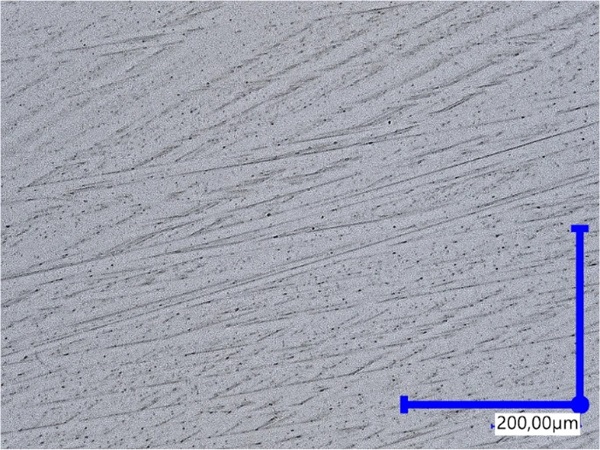
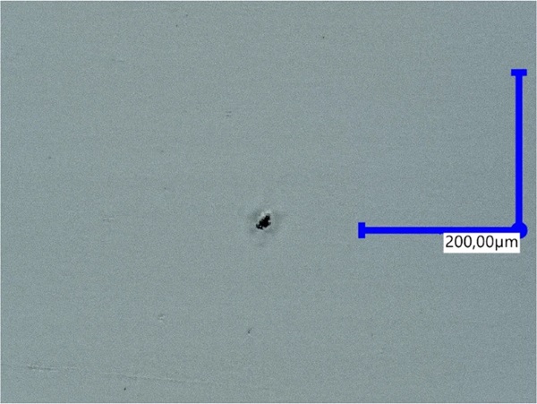
Figure 3 shows an a-typical example of a polished side surface with a 10 µm diameter defect visible. This was the largest defect on a polished surface that was found. The defect shape suggests that an internal defect was originally present here in the glass such as a stone or a bubble.
The arris are very variable in their quality. A typical example is shown in Fig. 4. An a-typical example is shown in Fig. 5 with a 200 µm diameter defect, the biggest that was found in this study. Considering the shape and size most likely an internal defect was present which was opened up by the edge processing. The arris typically has a diagonally striped appearance. In general although the appearance of the arris is rough, the surface is in actuality flat to 2 µm. The stripes being the result of small particles of glass being abraded from the surface by the rotary action of the chamfering head.
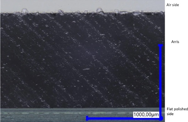
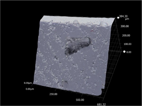
The top of Fig. 4 makes clear that the intersection of the flat surface and the arris is the most damaged area. Figure 6 shows this in 3D. The rotary action of the machine making the arris is taking shell like bites out of the flat surface. Figure 7 shows this damage from the top, looking down on the Sn surface of specimen S1. Defects are up to 60 µm in diameter and 20 µm deep. These can be single defects as seen in Fig. 6, but also a continuous series of defects such as seen in Fig. 4.
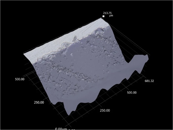
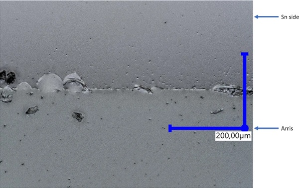
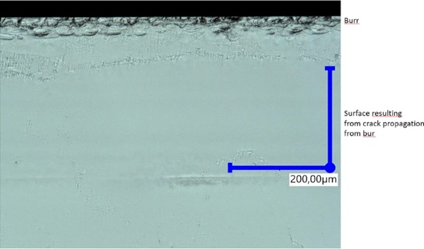
Figure 8 shows the original score made on the cutting table when the strips were cut out of the jumbo plate. The original score was some 30 µm deep and slightly irregular. But this score propagated into a clean cut.
In summary the quality of the glass was very good compared to for instance the glass used in Veer and Rodichev (2011), but at the intersection of the air and Sn surfaces with the arris there is significant damage produced by the rotary process that produces the arris. Other damages are incidental and rare and seem to be the result of internal defects.
Shoal like fragments are being cut out of the air and Sn surfaces while making the arris, effectively producing a continuous line of damage some 20 to 60 µm wide and several µm deep. When the glass is tested flat this should provide a significant stress concentration at the lower edge.
3 Experimental method
All specimens were covered using 38 mm wide transparent Temflex 1500 self-adhesive plastic foil. The 38 mm strip being placed in the centre of the flat surfaces the specimen so that the outer 6 mm on each side was free from tape allowing for easier microscope study.
The specimens were then tested in four point bending on a Zwick Z10 using test expert 3 software. All tests were conducted using a displacement rate of 10 mm/minute. This relatively high test speed limits any effects of stress corrosion. All specimens were tested in the lying position (out of plane). The span between the support rollers was 220 mm, the span between the loading rollers was 110 mm. A polystyrene foam block was placed between the support rollers to”catch” the specimen after failure and prevent additional damage. The position of the rollers was marked on each specimen with a permanent marker. The failure origin; left side, right side or on the flat surface was noted down after every test. Specimens from strips A to M were tested with the Sn side in tension, specimens from strips N to X were tested with the Air side in tension.
After testing, the origins of failure of selected broken specimens were examined using a VHX 7000 digital microscope. Some specimens were carefully unwrapped and shortened in order to study the actual fracture surface using a VHX 7000 digital microscope using magnification appropriate to the defect being studied, usually in the 50 × to 200 × range.
4 Results
From the forces at failure the bending stresses were calculated for all specimens according to EN 1288-3:2000. The detailed results are given in Appendix 1. Table 3 summarises the results of these tests. It also contains a summary of unpublished tests done by the author in 2015 on 8 mm thick specimens; length 300 mm, width 60 mm, with a similar flat polished edge and arris finish. The glass was prepared at the same factory as the 2023 specimens, but on older machinery which was changed in 2020. This as a comparison to the current data. Unfortunately the 2015 specimens were accidentally disposed of and were not retained for later digital microscopy as was originally intended.
Table 3 Summary of results of 2015 and 2023 tests, details for 2023 tests are in appendix - Full size table

4.1 Digital microscopy of the specimen fracture zone
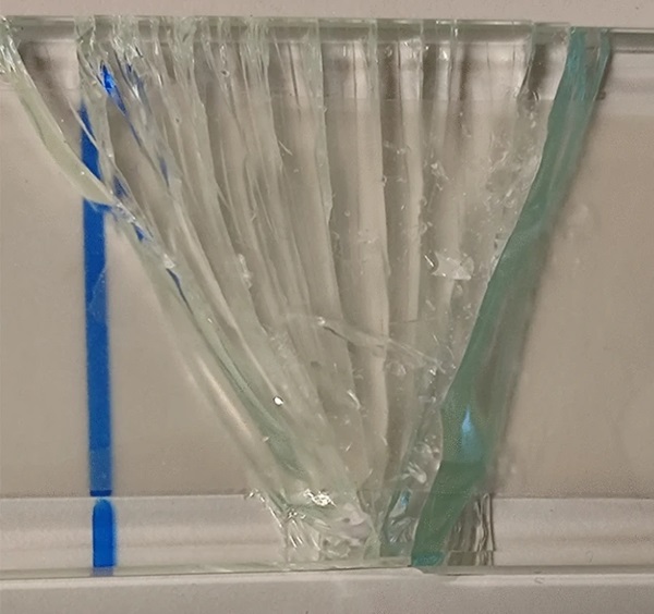
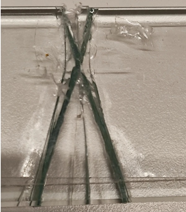
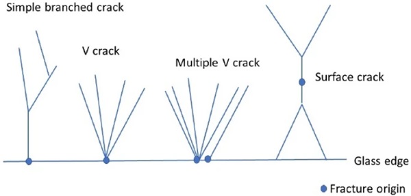
Three types of failure pattern were observed in these tests:
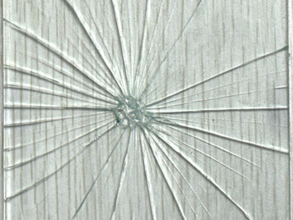
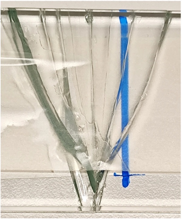
- Single crack originating from the edge which later bifurcates (Fig. 9)
- Multiple cracks originating from the edge some of which bifurcate (Fig. 10)
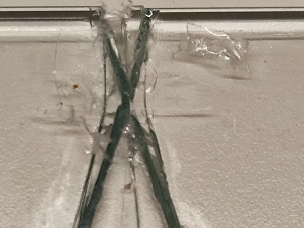
- Crack originating on the flat air or Sn surface which bifurcates in two directions creating an X shape (Fig. 11)
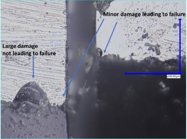
A selection of specimens were used to study the fracture origin. This led to very mixed results. An example is Specimen W4 which has a single edge failure, shown in Fig. 12. The failure started at a 20 µm length defect, but there is a much larger 50 µm length defect 20 µm to the left of the fracture origin. Some specimens like V4 macroscopically seem to show the crack starting at a point at the intersection of the arris and the air surface, but microscopically show some unusual damage next to this point on the air surface. This is shown in Fig. 13. So the crack might have originated at the intersection of arris and air surface, but more likely originated at the air surface close to the arris, creating the 8 shaped surface damage which then propagated up and down (using the coordinates of the photo). Some specimens, such as S1 in Fig. 14, seem to conform to conventional theory in that the origin of fracture seems to be at the point of a large defect.
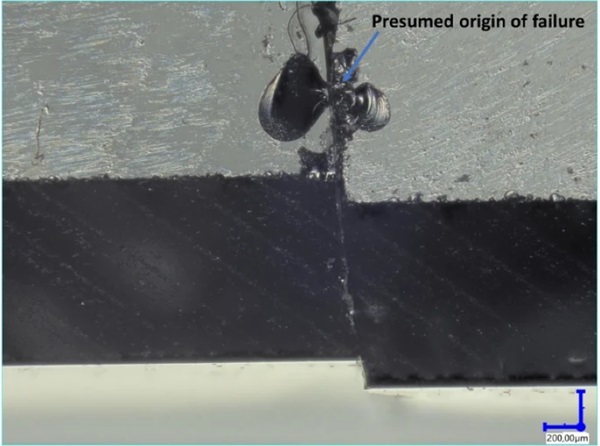
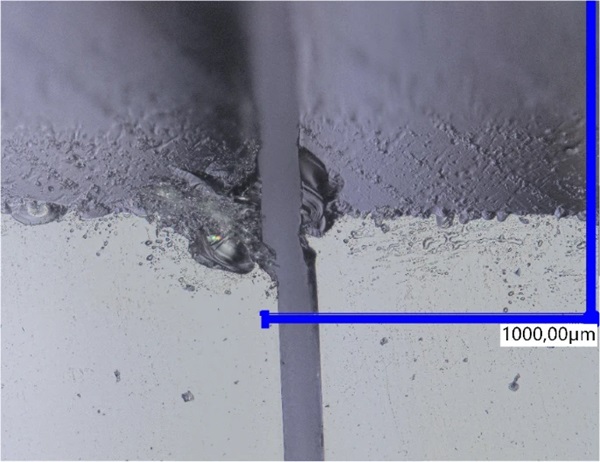
In the case of the surface failures the results are again very variable. Figure 15 shows specimen W3. The damage is very asymmetric, the right hand side damage almost suggesting an explosion in the glass, while the left hand side damage is comparatively minor. Figure 16 shows the surface fracture initiation point of specimen B2 which failed at high stress. Damage is severe on both sides of the fracture, but there is also clearly material missing. This is a common problem with high strength specimens, the energy release at high failure stress resulting in local fragmentation and spalling leading to missing pieces.
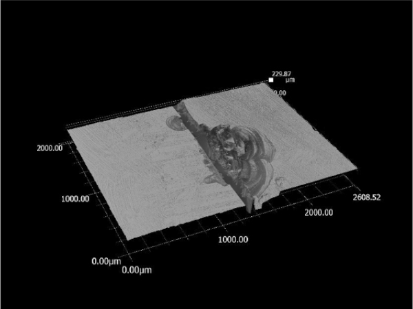
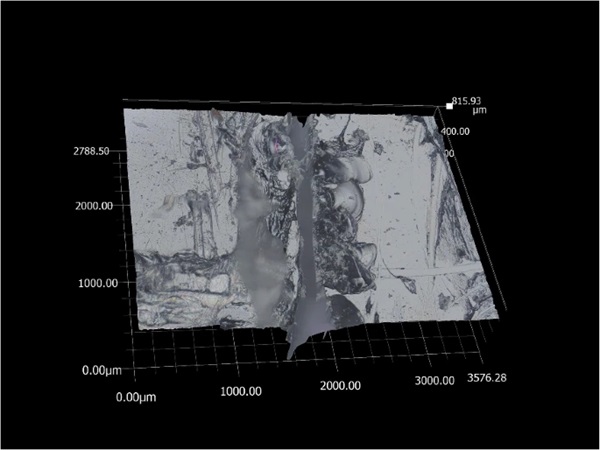
For the edge failures, the observed fracture origin is always in a defect at the intersection of arris and air or Sn side, however the fracture origin is not always at the largest local defect. In the case of surface failures severe damage is observed at the fracture origin. This damage was not present before the test. However this damage can be a-symmetric and no clear surface damage can be observed at the fracture origin. Failures at high stress are difficult to analyse as the fragmentation and spalling at the fracture origin due to the high energy release complicate the analysis.
4.2 Fractography
From the fracture pattern the origin of failure can be determined, Bradt (2011). Figure 17 shows the crack patterns found in this study and shows the points of origin of the failure. Using this and knowing which side was in tension, the self-adhesive foil of a number of selected specimens was cut very carefully so that the fracture surface could be studied. In glass failure there is usually a standard pattern visible on the fracture surface, Mecholsky (1994). The ASTM version of this standard pattern is shown in Fig. 18.
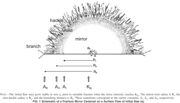
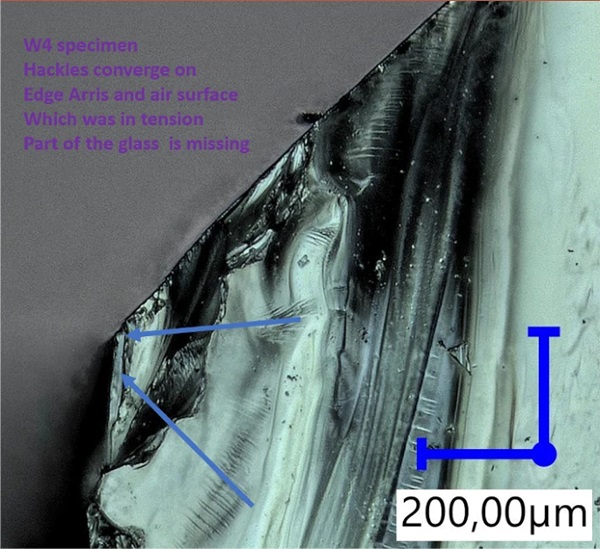
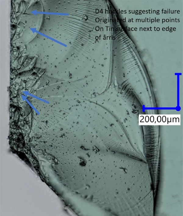
However in this study only parts of this pattern could usually be identified. A disadvantage of the out of plane bending test is that the tensile stress is concentrated in the outer layer due to the low thickness of the specimen and the stress gradient is steep. Figure 19 shows the fracture surface of specimen W4 which failed from the edge. The hackles are visible and the lines of the hackles indicate the boundary of the arris and the air surface as the origin of failure. However the mirror zone is missing as this part appears to have separated during fracture. Some specimens which from the failure pattern were assumed to be edge failures turned out to be surface failures originating close to the edge. Figure 20 shows the fracture surface of specimen D4. The hackles point towards two locations on the Sn surface within 0.5 mm of the edge of the arris. No clear defect is visible.
The clear surface failures can also be difficult to interpret. Figure 21 shows the fracture surface of specimen G4. There is a clear mirror, mist and hackle region. The spikes in the lower centre are the results of three cracks which are at slightly different locations along the length coalescing into a single crack. However there is no defect visible which would indicate a fracture origin.
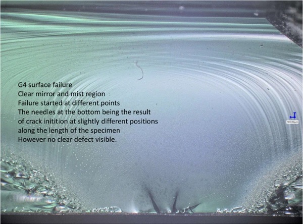
Figure 22 shows the fracture surface of specimen V3, the top view of which is given in Fig. 15. The fracture surface is that of the damaged part on the right side of Fig. 15. Figure 15 suggests that the failure was progressive and in steps. The fracture surface shows a dimple on the left, which is the part shown in Fig. 15 but this has detached/disintegrated during fracture. The fracture surface does not show any fracture source or a clear mirror/mist pattern.
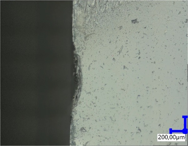
The primary conclusion is that many specimens show some evidence of the mirror/mist/hackle pattern, however there also specimens that do not. The actual origin/source of failure cannot be identified on the fracture surface in most specimens. This suggests that in certain cases the mechanical defect that results in failure is not pre-existing but is the result of a local volumetric collapse in the glass surface.
4.3 Statistical analysis of failure strengths
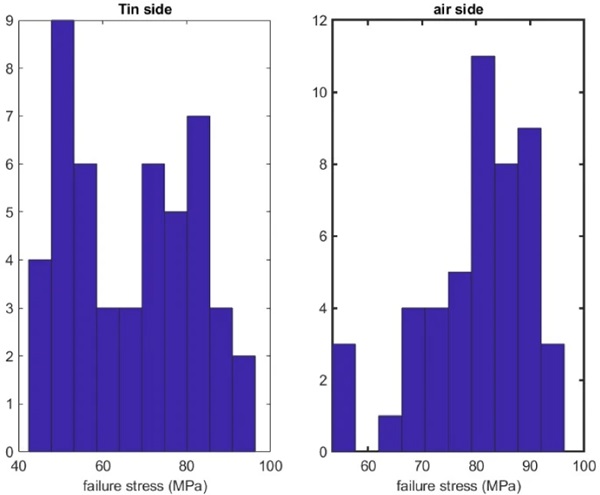
If we analyse the air side and Sn side data separately it is seen, in Fig. 23, that they have different distributions. The Sn side data having a lower and a higher peak and the air side one peak on the right side of the distribution. If the data are Weibull plotted, as in Fig. 24, the reason becomes apparent. The air side data has a close to uni-modal Weibull plot, the Sn side data has a bi-modal Weibull plot. Looking at both plots more precisely the deviation from uni-modal Weibull behaviour is only when the failure strength is below 55 MPa. This is less visible in the air side data as there are only three data points with a failure strength < 55 MPa, while the Sn side data has 15 data points with a failure strength < 55 MPa.
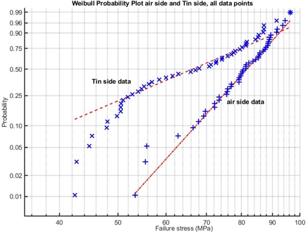
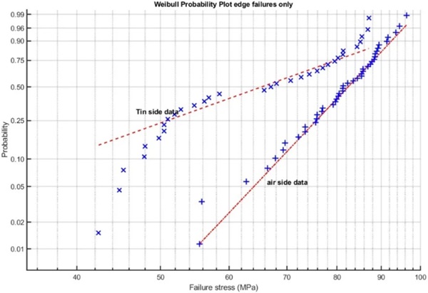
It is however clear that the Weibull modulus of the data with failure strength > 55 MPa is different for the air and Sn sides. This might potentially be caused by the Sn side having 16 surface failures while the air side only has 6 surface failures. Figure 25 shows a Weibull plot of both data sets without the surface failures. There is no difference in the pattern seen in Fig. 24 as the surface failures are well distributed over the entire strength range. Thus the data set with both edge and surface failures are considered by the author as a single coherent statistical data set. This implies that both edge and surface failures are mechanically equal in that both are the result of defect based failure mechanisms.
Although Fig. 24 shows a clear difference between air and Sn sides, this difference is less clear in other data sources. Plotting the unpublished 2015 data which was summarized in the results section, results in Fig. 26. Although the differences between air side and Sn side are much smaller, it is clear that there is still a systematic difference between the two data sets, which qualitatively is the same as in the 2023 data set. As the glass from the 2015 tests is significantly less strong on average than the glass from the 2023 data set the deviation from the Weibull line at lower strength values is more visible, although the strength at which the data deviates downwards from the Weibull line is around 44 MPa.
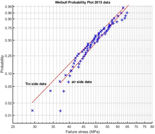
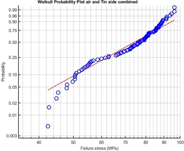
Figure 27 shows a Weibull plot of the combined air and Sn side data, thus mixing two distinct statistical groups into a single data set. The result of mixing is that the plot becomes tri-modal with a downwards sloping lower strength, a somewhat straight middle part and an upwards sloping upper part. Comparing Figs. 24 and 27 it is clear that separating the data sets is essential to obtain a clear and mathematically valid statistical interpretation. Even when the data sets are closer, such as in Fig. 26, separating the data is strongly advisable if the data are to be used to calculate a probability based 1/10.000 failure stress.
It is noted that both the 2015 and 2023 specimens have a similar chemical composition and that both sets were annealed. No pre-stress could be measured using a SCALP 5 laser scanner. So compositional differences or pre-stress variations cannot explain the different results.
4.4 Micro-statistics of the different float glass strips
The advantage of having the factory prepare 1 m long strips which are later cut into four equal specimens is that the statistical distribution of the strength within each strip can be studied. Although the small size of the specimens would increase the strength according to the ASTM C158, this still should allow for a comparison between strips, even though only four data points are available for each strip.
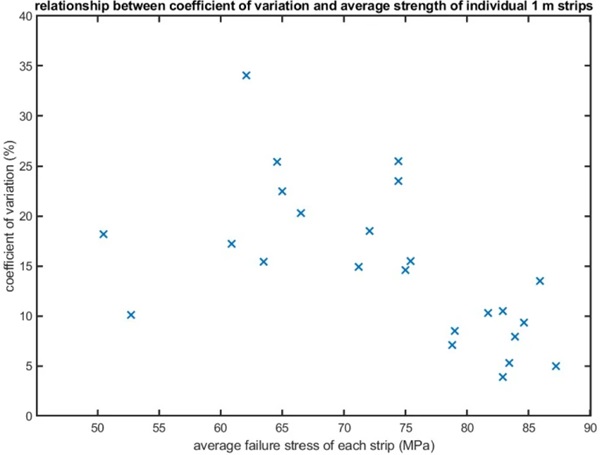
For each strip the mean strength and coefficient of variation was determined based on the 4 test results. This is plotted in Fig. 28. Although there is no clear pattern, one third of the results have a high mean strength and low coefficient of variation. This suggests that the glass industry can currently produce 1 m lengths of edge processed annealed float glass with an average strength > 75 MPa and a coefficient of variation < 10%, although a larger statistical base is required to mathematically validate this. However the overall average strength is reduced and the coefficient of variation is increased by some strips with low average strength and some strips with a high coefficient of variation. These statistical outliers are located in a limited number of strips, however they dominate the strength statistics of the over-all data set and thus reduce the overall engineering strength of the glass.
5 Discussion
The glass specimens used for this research have had high quality edge processing as the strength data shows when compared to the 2015 data or those given by Veer and Rodichev (2011). As the large number of surface failures show, the strength of the edges is comparable to the strength of the surface.
It is also clear that there is a significant difference between testing with the air side or the Sn side in tension. On average the Sn side is weaker but more importantly the air and Sn side in tension data have to be regarded as two separate statistical groups. In a Weibull plot they show clearly different Weibull moduli. It should be noted that when Weibull developed the statistical distribution that bears his name, Weibull (1939), and which he tested on glass, float glass did not exist and the glass extant then would not have a Sn or air side.
It is also important that the Sn side has more surface failures, 16 to 6 in this test series. This could be due to surface damage from the ceramic rollers in the annealing lehr. However there is no microscopic evidence for such damage. The increase in surface failures could also be due to the differences in the glass network density. When the glass is cooling down in the float oven, the glass network is forming. The network density is dependent on the cooling rate. As the Sn side is floating on top of a large mass of molten metal it is quite probable that the cooling down on the Sn side is slower. Glass network density is highly dependent on the cooling rate during “solidification”, Ito and Taniguchi (2004). It is thus quite plausible that under the Sn side surface, the glass has a different network density than at the air side. This would imply different mechanical properties for the glass in the air surface and the Sn surface. As it is established practice to score glass on the air side, because the air side is easier to score, the difference in mechanical properties between the two sides is in actuality well established.
Also when checking the arris on air or Sn side, no evidence of extra damage on the air side was found which could be attributed to the original scoring damage on the air side. Considering this the author sees no reason to assume that mechanical damage from roller contact or scoring is responsible for the observed differences between air and Sn side in these tests.
It should be noted that all tests were conducted with the glass flat. If tests are conducted with the specimens standing it is not known if there is a preference for failure starting from the Sn side. Based on the evidence from the tests in this paper it cannot be ruled out that in tests with the specimens standing, there could be a preference for failing from the Sn side, which would affect the failure statistics. This is again a point for further research.
If we look at the results with failure stress > 55 MPa, the results for both Sn and air side effectively show uni-modal Weibull behaviour. If specimens with a failure strength < 55 MPa are included a bi-modal Weibull curve results, the lower strength data apparently converging to a lower bound strength. This is in agreement with earlier results and with the lower bound glass strength theory of Ballarini et al. (2016).
Statistically both surface and edge failures seem to fall on a single uni-modal or bi-modal Weibull curve. This suggests that in both cases the same defect based, LEFM controlled, fracture mechanism dominates. As this is true for both air and Sn side data, the differences in fracture morphology cannot explain the differences between air side and Sn side behaviour. There must thus be a physiochemical reason for this difference. In part this will be due to the Sn side being infused with Sn atoms which would change the mechanical properties. The other part could be due to a different network density in the glass directly under the SnO2 layer due to slower cooling during “solidification” in the float oven. This requires significant further research to elucidate.
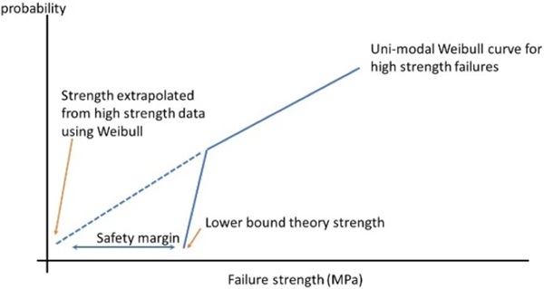
The critical engineering question is how to calculate the design strength of float glass. Figure 29 illustrates this problem. If the uni-modal Weibull line from the high strength data is extrapolated downwards this results in a very low estimate for the 1/10.000 design strength. If the lower bound theory is valid, a much higher design strength is valid. The difference between the two creates a significant margin of safety but also means glass is currently significantly over-dimensioned during design. Thus further investigation into the validity of the lower bound strength theory is essential to properly dimension glass and to achieve an eco-impact reduction by reducing the amount of glass used.
The next point to address is the role of the surface failures. In recent tests on float glass using the co-axial ring on ring method, Veer et al. (2023), a significant strength difference was observed in new glass between the air and Sn sides. Table 4 compares the strength of the surface failures in four point bending discussed in this paper with the strength data found using the co-axial ring on ring method. Digital microscopy was used on both the coaxial ring on ring specimens and the four point bending specimens by the author and the surface of the new glass samples are comparable.
Table 4 Comparison of surface strength of new glass measured with 4 point bending test with data from ring on ring testing on new glass - Full size table

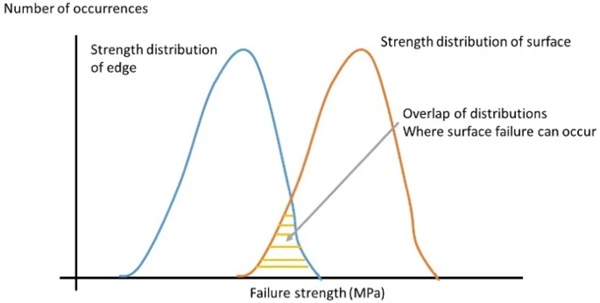
The minimum strength values found by the co-axial ring on ring method are smaller than the maximum strength values of the specimens failing from the surface in four point bending. This suggests that in four point bending, where the entire surface that is in tension is subjected to the same tensile stress, failure starts at the weakest spot, which can be on the surface or at the intersection of the arris and the surface. Increasing the quality of the edge will thus only increase the relative numbers of failures starting at the surface. Thus there is a competition between the failure modes, schematically illustrated in Fig. 30. Both the edge strength and surface strength have a separate distribution. Where the two distributions overlap surface failures will occur. It should be noted that as there is a lot more stressed surface area than stressed edge area, even if the average strength of the surface is far greater than the average strength of the edges, the larger surface area increases the probability of a surface failure initiating. Increasing the average edge strength moves that distribution to the right, increasing the relative number of surface failures. As the actual distributions are not known, Fig. 30 schematically uses Gaussian distributions for simplicity, although the actual distributions are likely to be different.
The results are in agreement with the minimum strength theory proposed by Ballarini et al. (2016). More recent research by Pan et al. (2024) shows that damaging annealed float glass reduces the strength to a certain minimum value. Increasing the damage above the level that corresponds to this minimum strength does not result in a decrease in the strength. In that sense the minimum strength theory can be reformulated as a maximum damage theory, in that the amount of damage that can be inflicted on annealed float glass has a limit. This also implies there is a physical effect causing the lower bound strength and that this is not the result of the statistical method. In that sense the data close to the lower bound strength value and some value above the lower bound strength could be physically and thus statistically separate. However significant further research in relation to damage, edge processing and the differences between air and Sn sides is required to solve this problem.
The quality of the edge Is however important for the actual strength that is measured. Looking at the data of the individual strips from which the specimens were cut, it is clear that one third are high strength specimens with a low coefficient of variation. A good example of this is strip P, with an average strength of 87.2 MPa and a coefficient of variation of only 5%. This is in contrast to strip H with an average strength of 62.1 and a coefficient of variation of 34.1%. Where the 4 specimens from strip P had 4 comparable edge failures; strip H had one low strength edge failure, one surface failure and two comparable edge failures. The outliers, such as those in strip H are the ones that lower the overall statistical strength. Clearly industry can produce glass with high strength and low coefficient of variation but currently cannot consistently do this. This is again a point for further research.
One problem is that microscopic examination of the fractures and fracture surfaces does not show a clear correlation between visible mechanical damage and the origin of failure. Although the current LEFM based theory of glass failure is well established and the failure statistics do not contradict this theory, the results suggest that there might be some form of stress concentration in or on the glass which cannot currently be identified with digital microscopy alone. This should also be a point for further research.
6 Conclusions
From the data the author concludes that:
- The air and Sn side of float glass should be regarded as separate statistical groups for the statistical analysis of the four point bending strength of float glass.
- The results are in agreement with the lower bound strength theory for float glass proposed by Ballarini et al. (2016).
- The minimum values for the strength of float glass found in co-axial ring on ring testing are comparable to the maximum values found for surface failures in four point bending in the tests analysed here and in Veer et al. (2023). It is not certain that this is universally applicable.
- If properly processed the edges of float glass can be stronger than the lower bound values of the surface strength of float glass.
- The strength of float glass in out of plane four point bending is thus governed by both surface and edge strength, failure being a competitive mechanism looking for the point with the lowest strength at a given stress level.
- Failures in out of plane four point bending do not always correlate to visible defects.
- There is no visible difference in defect size between air side and Sn side.
- It is possible that the difference between the average strength between the air and Sn side is caused in part by physiochemical differences between the two sides.
- In one third of the strips produced there is a combination of high mean strength and low coefficient of variation suggesting that edge processing can reliably produce glass with a high design strength. It should be noted that considering the low number of specimens in each group (four) this could be a random event and further research using a large sample size is required. There are significant areas for further research to answer the questions raised in this research.

