Authors: Martien Teich, Christian Scherer, Miriam Schuster, Max Brandenstein & Michael Elstner
Source: Glass Structures & Engineering (2024)
DOI: https://doi.org/10.1007/s40940-024-00276-x
Abstract
Many office and residential buildings in Europe need to be renovated in the near future to meet current energy efficiency requirements. This often comes down to updating the insulation performance of the building envelope including the windows. Most “old” windows consist of a frame and a double insulated glass unit (IGU) or even monolithic glass panes – typically without any low-e coating. These non-coated double glazings have a Ug-value of 2.7 W/m2K (single glazing even 5.2 W/m2K). Modern coated triple glazed IGUs provide Ug-values of up to 0.5 W/m2K.
This paper deals with the question of how old insulating glass units can be re manufactured to match the state of the art in terms of the energy efficiency. For this purpose, dismounted IGUs from the 1980s are used. After analyzing the remaining functionality, the double IGUs are disassembled. The single glass pane is cleaned, and the old edge sealing is removed. The old glass pane is combined with a new coated low-e glass and a spacer system to form a new upgraded IGU with warm edge technology. This study demonstrates that remanufactured IGUs can achieve the performance of IGUs made from new glass.
1 Introduction
Sustainable design principles are gaining momentum in the construction industry. Among other things, the emission of greenhouse gases (usually measured as CO2 equivalent) needs to be reduced significantly. Waste avoidance and recycling of building materials are particularly important. Compared to the total construction volume, glass is of secondary importance. Nevertheless, this material significantly determines the CO2 footprint of a transparent building envelope.
A prominent example of reducing the CO2 footprint through improved glazing is the Empire State Building. The original double insulated glass units (IGUs) were disassembled, cleaned, and then remanufactured to new triple IGUs using warm edge spacers, suspended low-emissivity films and a mixture of krypton and argon. The upgraded windows should save 1,150 t of CO2 a year. In addition, 96% of the existing glass and frames were reused (Kennett 2010).
In order to mechanically disassemble old or faulty IGUs into individual panes, IG2Pieces was recently developed (HEGLA GmbH & Co. KG 2023). Also, GSF produces circular IGUs (isoMAX) from dismantled and disassembled IGUs. In research, new IGU designs, which intend to significantly increase circularity through reversible connections are studied, see e.g. Kouvela (2022).
Depending on the application, the glass must fulfill certain requirements. These include optical, physical (e.g. U-value, sound insulation) and mechanical requirements (strength). To reuse or remanufacture glass, these properties must be assessed. However, there are currently no established codes or principles that can serve as a guideline to qualify glass for further use in the material cycle.
A few papers were published dealing with the mechanical performance of aged glass. The results of these investigations differ which is due to many possible influencing parameters (including installation location, age, etc.), different sample sizes and test configurations. Zammit & Overend (2010) investigated annealed glass which has been exposed to natural weathering for more than 20 years. They observed a 7.2 times larger failure load for new glass than for weathered glass (failure load ratio weathered / new = 0.14). Datsiou & Overend (2017a, b) investigated naturally aged samples exposed to natural ageing for 20 years as part of a façade in Norfolk, UK. The low-rise building was situated in a rural location with a distance greater than 10 km from the coast. At the lower failure probabilities, an 85% reduction in strength was observed compared to new glass products.
Datsiou & Overend (2017a, b) depicted a decrease in strength of 68% for artificially aged glass (sand abrasion, equivalent to erosive action of 20 year) compared to “as-received” annealed glass. Sofokleous (2022) observed in her investigation a ratio between the strength of the inner and outer surface of up to 69%. Her samples had an age of 55 years and were installed in a high-rise building in Den Haag (NL). Rota et al. (2023) recently examined a large number of 28 to 41-year-old IGUs. Depending on the optical appearance (flaw distribution determined with scanner), the samples were assigned to quality class QL1 – QL3 according to DIN EN 572–1 (2016–06). For QL 1, a characteristic strength of approx. 55 MPa was obtained (261 samples in total, ring diameters 20 mm / 80 mm and 40 mm / 80 mm). They also tested a reference series of “new” glass (ring diameters 40 mm / 80 mm) and obtained a characteristic strength of 58 MPa, which means that QL1 has a mechanical performance comparable with new glass. QL3 reached a characteristic strength of 37 MPa.
Zammit & Overend (2010) observed an increased roughness of the weathered glass surface by performing atomic force microscopy of the glass surfaces. In 3D surface maps they detected large differences in the valley depths of a weathered and non-weathered surface, which is why they recommended surface characterization for a preliminary assessment of glass to indicate the degree of weathering when considering refurbishment or glass reuse.
There is limited data in the literature on the physical performance of old IGUs. van Nieuwenhuijzen, Tetteroo, van de Vliet & Melet (2023) performed non-invasive argon measurements (using the Sparklike Laser Portable) on several IGUs in use at different locations in the Netherlands (Amsterdam, Rotterdam, Utrecht). The IGUs were manufactured between 2002 and 2013. Argon concentrations between approximately 5% and 96% were measured. In addition, they recommend different circular strategies based on the age of the IGU and the level of argon concentration: IGUs less than 15 years old with argon concentrations above 85% are suggested for direct reuse or retrofit with an additional glass pane, while older IGUs and those with lower argon concentrations should be disassembled for glass reuse or recycling.
This paper provides additional research and insights on the reuse and remanufacturing of flat glass products with a focus on IGUs. It complements the work by Reshamvala et al. (2024) which conducted life cycle analyses considering different R-strategies.
Following an introduction to the various R-strategies and a description of the dismantling process of IGUs from buildings, the results of experimental investigations on disassembled IGUs and on the individual glass panes are presented. The tests include the evaluation of the gas fill level and the moisture content of the IGUs, as well as roughness and strength tests on the individual glass surfaces. The roughness and strength of the glass surfaces are compared to ascertain whether a correlation is recognizable. Finally, some of the individual panes are processed into new IGUs and subjected to standardized tests. Preliminary results indicate that remanufactured IGUs meet modern energy efficiency standards.
2 R-strategies and retrofit possibilities
2.1 Material cycle
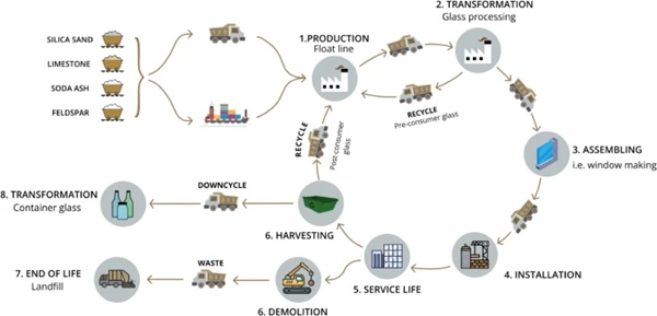
Sustainability starts with quality in design, fabrication, and execution. The chosen and qualified glass products should be suitable for the respective application with the longest possible service life. At the end of its service life, the glass products can be reused, remanufactured, or recycled by returning glass cullets to the float process. The primary objective should be to sustain glass within the material lifecycle at a consistent level of quality for prolonged durations, thereby mitigating the necessity for fresh raw materials and diminishing emissions stemming from procedural and energetic sources of greenhouse gases. If possible, the recycled material should not be utilized for alternative products, including glass wool, glass bottles, foam glass, or as filling material for road construction. Furthermore, disposal in landfill sites must be avoided.
Which of the various options is most suitable in a specific case must be decided by the parties involved on a case-by-case basis. Figure 1 shows several possibilities for reuse and recycling of glass. On one end of the spectrum lies the "linear" model, wherein glass is disposed of in landfills upon reaching the end of its operational lifespan. Alternative avenues entail repurposing glass for subsequent processes or applications, such as recycling glass cullet for the fabrication of other products (although not the preferred course for flat glass), integrating glass cullet into the float glass manufacturing process, or straightforwardly reutilizing flat glass, as discussed within this research.
This paper considers three stages of the circular economy:
- Reuse such as the installation of a removed insulating glass unit elsewhere. For this purpose, the product properties required for the intended use, such as Ug-value or strength of the removed glass, may have to be assessed.
- Remanufacturing: Further use in which the old glass is upgraded (e.g. refilling the IGU cavity) or separated into its individual components and assembled into a new product (e.g. production of a new IGU with both old uncoated and new coated individual panes). The product properties of the individual components and their suitability for further processing must be assessed.
- Recycling where removed glass is returned to the material cycle in cullet form, and ideally flat glass is produced from it again. It is important to separate the glass qualities and glass structures by type.
Reuse and remanufacturing are sometimes summarized under the generic term reuse. In some cases, further R-stages such as refurbish or repair are introduced in literature (e.g. the 9r Framework, (Potting, Hekkert, Worrell, & Hanemaaijer 2017), (Zhang, et al. 2022)). For the purpose of maintaining clarity within this paper, the nuanced differentiation among the R-strategies is intentionally omitted.
2.2 Effect of glass type
The possible reuse/recycling of glass depends largely on the type of glass. Glass for Europe (2023) discusses reuse possibilities depending on the glass type. Tempered or soft-coated glass is usually recycled. Printed (enameled) glass is only suitable for recycling in the float process to a limited extent due to its color. Glass with a high post-consumer cullet content is not produced as low-iron glass, but mostly as mid-iron or normal float glass.
Annealed (float) glass panes are particularly suitable for reuse. These were often used in multi-pane insulating glass units for residential and office buildings. Non-tempered, annealed glass can be cut and further processed. This applies both to individual panes of glass and to laminated glass. However, the reuse of toughened glass panes is also possible if they are further processed in the same format (e.g. into laminated safety or insulating glass)—but this either restricts their reuse or requires a different design process than today, in which the available building products must be considered in the early design phase.
3 Dismantling and remanufacturing
3.1 Dismantling glass
The documentation of existing glazing before demolition (“pre-demolition audit”) can be aligned with DIN SPEC 91484 (2023–09) "Assessment of the reusability of building materials prior to demolition and renovation work". The aim of the documentation is to record the existing glazing of a building in a sufficient and standardized way, which is the prerequisite for the highest possible quality of subsequent use and thus for a circular economy in the construction sector. Possible subsequent reuses of the glass are significantly influenced by its condition (e.g. damage, contamination, discoloration), exposure to harmful substances, the possibility of non-destructive dismantling and the technical properties.
Inventory and documentation usually take place in two stages. Firstly, basic information is collected and recorded to obtain an overview (e.g. quantity and size of the glass). The initial aim is to determine which glass can be considered for reuse. In a second stage, the necessary detailed information (e.g. dismantling options) is recorded. The more information available from the design/construction phase, the easier the documentation will be. The basic procedure is outlined in Fig. 2 in DIN SPEC 91484 (2023–09).
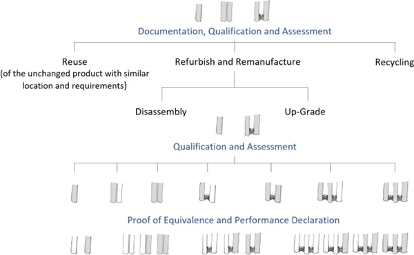
Depending on its use, the glass is removed and stored temporarily due to the time lapse between removal, processing, and installation. Expertise is required for these steps. Adequate premises and storage facilities (e.g. glass racks) must be available for storage. For guidance on transportation and storage protocols, the authors refer to Bundesverband Flachglas e.V. (2015).
3.2 Remanufacturing process
The removed glass is cleaned and either installed (reuse) or refurbished and then installed (remanufacturing) or sent into the float process in cullet form (recycling). The following steps (see also Fig. 2) are necessary for remanufacturing:
- Separate insulating glass unit into components if necessary
- Depending on the edge seal system, the insulating glass can be separated by hand. The process is time-consuming. Mechanical cutting processes are possible and offered by individual companies.
- Cleaning. The cleaning process must be adapted to the condition of the glass.
- Qualifying individual panes
- Visual quality: BF document 006/2019 "Guideline for assessing the visual quality of glass for the building industry" (Bundesverband Flachglas e.V., 2019) is often used for assessing the visual quality of new glass. There is no comparable guideline for deconstructed glass. The visual quality must therefore be agreed on a project-specific basis. The agreement of reference samples is recommended.
- Strength: The glass surface changes over time because of weathering and localized damage. This can affect the strength (Rota et al. 2023; Datsiou & Overend 2017a, b; Sofokleous 2022).
- Insulating glass units: The suitability of the glass surface for sealing the edge seal (primary and secondary seal) of insulating glass units must be tested at an early stage. Initial investigations indicate that durable insulating glass can be produced with existing glass using suitable cleaning and pre-treatment processes, see Sect. 4.3.
- Qualify remanufactured glass product
- The newly manufactured glass product from the individual panes must fulfil the product-specific standards.
3.3 Challenges
In assessing the potential for reusing building components, several key considerations must be taken into account. These include, but are not limited to, aligning objectives and procedures with the client, investor, architects, designers, and, where relevant, building product manufacturers prior to commencing the formal tendering process.
While the reuse or remanufacturing of previously installed building products may initially appear straightforward, further examination often reveals the necessity for a different approach when incorporating used building products. In essence, this process may encompass the following aspects:
- Inspection of the site
- Research and inspection of existing documents
- As-built investigation and documentation
- Selection and differentiation of building materials
- Creation of building component catalogue
- Expertise on hazardous substances
- Assessment of the building components—can existing windows and façades be retained?
- Assessment of service life
- If windows and façades are to be retained, the availability of spare parts for existing windows and glass façades becomes crucial for prolonging their usability and, consequently, extending the service life of the component. This includes essential elements such as fittings and seals.
- Building regulations
- Legal coordination (e.g. warranty risks)
- Description of the dismantling method
- Dismantling for test purposes
- Inspection of the condition of the structure and envelope
- Assessment of the supporting structure if loads increase
- Catalogue of measures—utilisation concept, investment costs
- Logistics of dismantling and disposal (storage areas for containers, trained specialist personnel for dismantling and sorting the building materials)
- Protection and storage of dismantled materials until reuse and reinstallation
Furthermore, it is essential to analyse the object comprehensively, taking into account factors such as its location, the structure of the building, the surrounding environment, and associated costs. Additionally, creating suitable conditions and a robust planning framework is necessary to address warranty risks in a manner that is realistically manageable for all stakeholders involved.
Finally, the execution of a trial dismantling procedure is paramount for both reuse and remanufacturing initiatives. Figure 3 presents images depicting older and newer window systems. Removing glass from existing windows is not always straightforward or feasible. Hence, it underscores the importance of conducting an inspection and conducting a trial dismantling process. This procedure should incorporate the following essential considerations:
- Description of the dismantling method
- Description of the installation method
- Definition of the removal points
- Necessary tools
- Working hours required
- Minimum number of persons
- Required installation tools
- Photo documentation of the individual steps
- Photo documentation of the results
- Description of condition
- Necessary securing and protection after dismantling
- Training and requirements for specialised companies
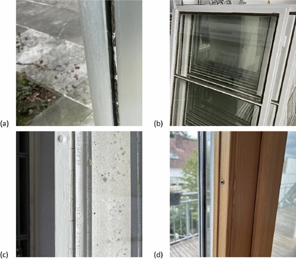
As depicted in Fig. 3 (a), the glass pane is set within an aluminum frame using putty. Given that putty lacks elasticity and tends to harden over time, removing the glass panes becomes exceedingly challenging. Consequently, the glass can only be dislodged from the frame, rendering it unsuitable for reuse as flat glass. However, it remains feasible to gather the fragments and reintegrate them into float glass production through controlled recycling. In Fig. 3 (b), a single glass installation with a putty bevel is illustrated, where subsequent removal is also improbable. In Fig. 3 (c), the glass may be detachable upon loosening the screws, albeit not as effortlessly as depicted in Fig. 3 (d). The latter showcases a modern timber window, wherein the pane can likely be removed due to the presence of intact and accessible screws, along with its installation utilizing elastic sealant.
4 Analyses and remanufacturing of IGUs
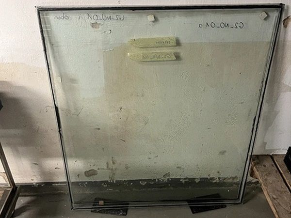
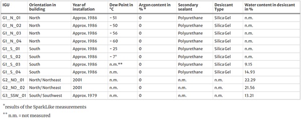
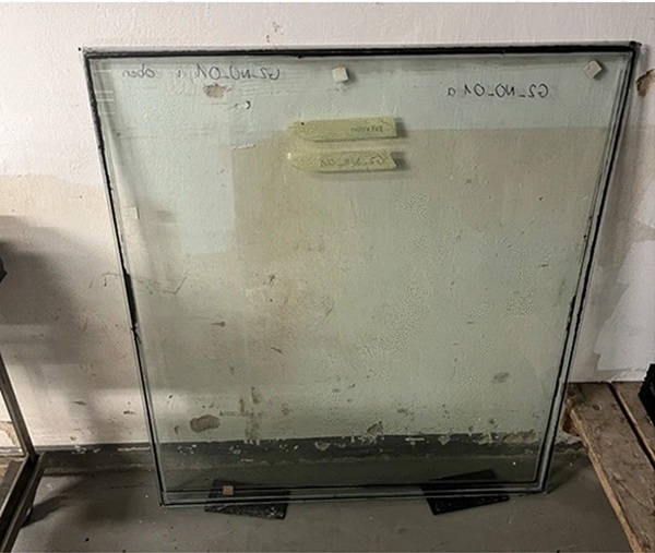
All investigations and test sample productions detailed in this chapter were conducted using IGUs of varying sizes and glass thicknesses, sourced from a building project in Regensburg (Germany) dating back up to 40 years. Table 1 provides an overview of all dismantled IGUs. Figure 4 illustrates an IGU that was installed in 2001 and dismantled in 2023. The process commenced with the assessment of the product properties of the dismantled IGUs. Subsequently, the IGUs were disassembled into their constituent components, namely sealing and glass panes, for detailed examination. Finally, new insulating glass units with different spacer systems were fabricated using the reclaimed glass after undergoing various pretreatment methods. Testing procedures were conducted in accordance with relevant standards.
Table 1 Initial test results of the deinstalled units - Full size table
4.1 Functionality testing and disassembly of the dismantled IGU
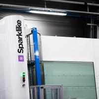
Before disassembling the dismantled IGUs, selected units underwent functionality analysis, including gas (argon) filling level and dew point determination. To gauge the argon content, measurements were conducted using both the SparkLike measuring device and a Helox 2 oxygen analyzer. The SparkLike device uses plasma emission spectroscopy, while the Helox 2.0 analyzer employs a paramagnetic measuring cell for selective oxygen measurement, enabling argon content calculation post-calibration.
A reliable method for assessing the integrity of an insulating glass unit is by determining its dew point. If the edge seal is compromised and the unit is not airtight, water vapor can infiltrate, increasing air humidity and subsequently, the dew point temperature. An ideal dew point temperature for a new insulating glass unit is below -60 °C. This temperature, specified in accordance with DIN EN 1279–6 (2021–05), serves as a critical quality criterion, ensuring prolonged service life of the insulating glass. EN 1279–6 outlines a qualitative measurement approach for assessing dew point temperatures between the glass panes of insulating glazing. This method involves placing a cooling cell on the glass surface, which is then cooled using cooling liquid (ethanol) and dry ice granules. The duration until condensation appears on the inner glass surface adjacent to a mirror is measured, allowing for the determination of the dew point at a cooling rate tailored to the glass structure.
Table 1 presents the results obtained from the disassembled IGUs. Notably, the SparkLike device did not detect argon in any of the units examined, while small amounts were identified in two IGUs using the Helox 2 analyzer. Although these readings, measuring approximately 4%, exceed the argon content of pure air (0.93%), the precision of the measurements suggests caution in concluding that these IGUs were originally filled with argon. Given the age of the panes (approximately 40 years), it is more probable that they were never filled with an insulating gas.
This inference is further supported by dew point measurements, which indicate that even after four decades, some of the insulating glass units with a northern orientation (G1_N_0x) exhibit adequate tightness. Conversely, those installed in a southern orientation (e.g., G1_S_01/02) demonstrate a notable increase in dew point temperature, suggesting damage and leakage of the edge seal likely caused by higher temperature fluctuations inherent to southern exposure. These fluctuations lead to intensified "pumping" movements of the IGU, thereby subjecting the edge compound to increased mechanical stress and heightening the risk of leaks.
In addition to the functionality tests conducted on the IGUs, analyses of the secondary sealing and desiccant were performed during disassembly into individual components. IR spectroscopy revealed the use of polyurethane as the secondary sealant and silica gel as the desiccant for all tested IGUs. The desiccant, typically filled into the spacer, serves to absorb moisture trapped during production and adsorb water molecules that have diffused into the cavity over time. While silica gel was traditionally used as a desiccant, molecular sieves, particularly zeolites, are more commonly employed today. The desiccant within the spacer underwent drying in an oven after initial mass determination to assess the gravimetric water content, providing insights into the extent of water adsorption capacity utilized over the years.
The IGUs were disassembled using a basic cutter knife. Warming the IGU to approximately 50°C for about ten minutes (Fig. 5 center) facilitated this cutting process. The temperature rise resulted in the expansion and softening of the edge seal, allowing for easy separation of the panes (refer to Fig. 5 right).

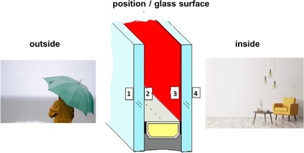
After disassembly, certain glass panes underwent analysis regarding glass quality (Sec 4.2), while others were utilized in the production of new IGUs (Sec 4.3). Subsequently, the glass surfaces of the old IGUs were labeled with numbers ranging from 1 to 4, as indicated in Fig. 6.
4.2 Inspection of glass surface roughness and strength
Destructive tests were conducted on glass panes from two IGUs (G2_NO_01 and G2_NO_02 of Table 1), totaling four glass panes investigated. These IGUs, measuring 985 mm × 1077 mm, were installed in 2001 in offices facing north-northeast. The outer glass panes had a thickness of 6 mm, while the inner panes were coated (coating detected with glass measuring device “GlassBuddy® Plus”) and had a thickness of 4 mm. All glass panes were annealed float glass.
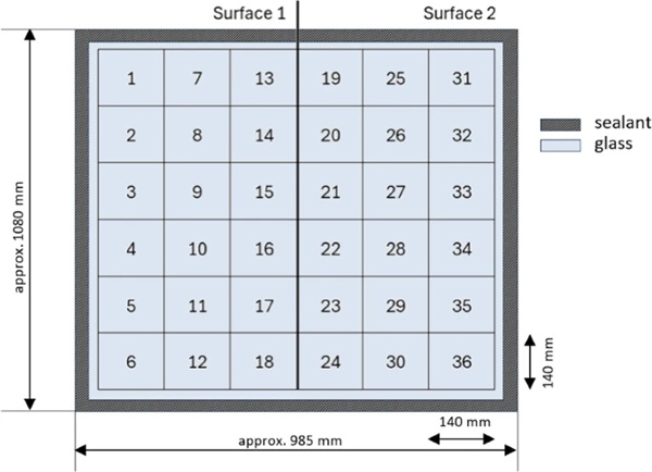
Prior to individual pane examination, cleaning with Isopropanol was performed. To assess both the top and bottom surfaces of each glass pane (thus, all four surfaces of the IGUs), each pane was halved. Subsequently, each half was divided into 18 square samples measuring 140 mm × 140 mm (as depicted in Fig. 7). This size selection ensured a sufficient number of samples for statistical analysis.
The average roughness depth Rz of each sample was measured at the center using the Universal Surface Tester (UST), depicted in Fig. 8 (a). The measurement parameters included a distance of 20 mm, a speed of 0.2 mm/s, and a constant measuring force of 10 mN. A 60° diamond cone probe tip was employed, meeting the specifications of (DIN EN ISO 3274:1998–04). The z-axis profile resolution was 60 nm.
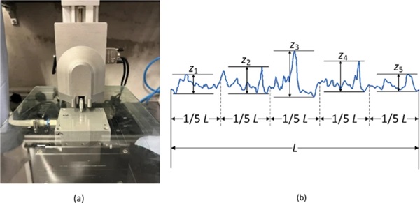
Rz is calculated by dividing the measuring profile into five sections of equal length and determining, for each section, the greatest distance zi from the highest peak to the lowest valley, as depicted in Fig. 8 (b). The Rz value is subsequently derived from the mean value of the zi values according to Eq. (1).
![]()
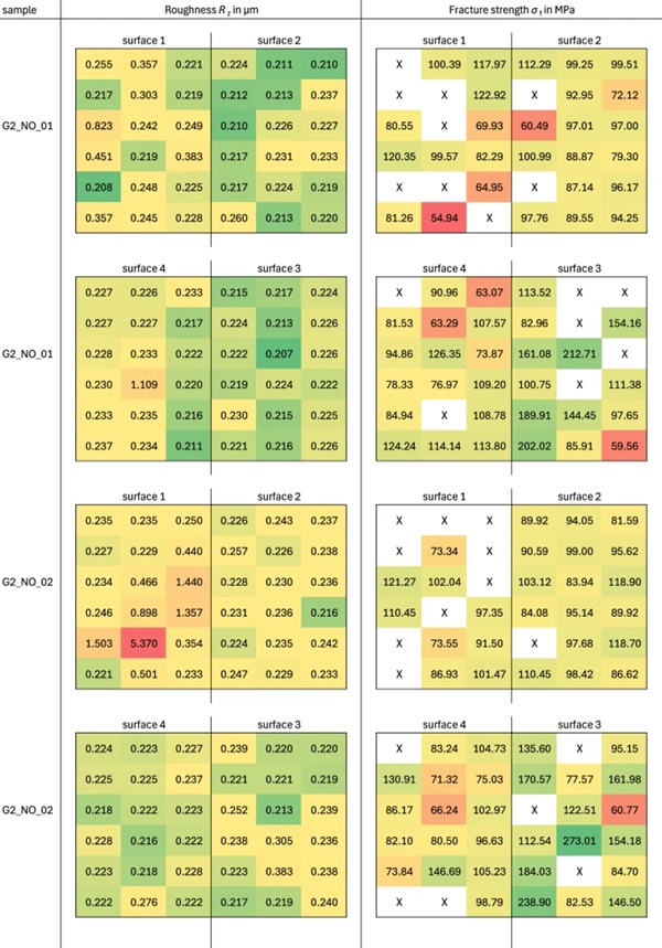
The roughness measurement results are depicted in Fig. 9 and Fig. 12 (left column). It's evident that surfaces 2, 3, and 4 exhibit similar average roughness. However, surface 1 (outer surface of the outer glass panes) shows a notably higher average roughness, particularly in the second IGU (G2_NO_02 from Table 1).
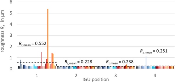
Surface roughness variability is greater for surfaces 1 and 4 (outer and inner surfaces of the IGUs) compared to surfaces 2 and 3 (sides facing the cavity). Additionally, the surface roughness of a reference glass pane ("new" glass) was measured and determined to be Rz,mean,ref = 0.23 µm, providing a basis for comparison.
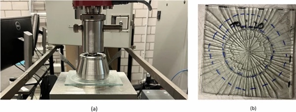
After measuring the roughness, the surface strength was assessed through double ring bending tests. The roughness was measured on the surface experiencing tension during the fracture test. Given the very low force (10mN) applied during roughness measurement, it is assumed that no significant additional damage is inflicted on the glass. The test setup and fracture stress evaluation followed EN 1288–5 (2000–09), albeit with differing ring dimensions. The load ring (80 mm) and support ring (120 mm) diameters were selected to maximize the presence of surface defects within the load ring, increasing the likelihood of strength reduction due to defects. Additionally, RFEM analysis ensured the absence of nonlinear effects with the chosen configuration. Since the samples are square, a mean sample radius (= 0.6 L) was determined for evaluation according to standard. Tests were conducted at a stress rate of 2.0 MPa/s. Figure 10 illustrates the test setup and a representative fracture pattern. To preserve the fracture pattern, an adhesive film was applied to the top side of the samples (load ring side) before testing commenced.
Due to differences in ring sizes and tested surfaces compared to the standard, a reference series ("new" glass) was also tested for comparative analysis. This reference series comprised 36 samples with a nominal thickness of 4 mm, with only the tin side being tested in this series.
Figure 12 (right column) shows the fracture stress for each sample in MPa. The values are categorized by color into "high" (green) and "low" (red). The mean values and standard deviations of the fracture stresses for all four surfaces are reported for each glass surface in Table 2.
Table 2 Mean fracture stresses, standard deviations, and coefficients of variation for each IGU - Full size table
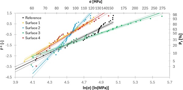
To ensure a robust statistical evaluation (Danzer et al. 2001), the fracture stresses of both IGUs were analyzed collectively. The IGUs shared the same age, size, and orientation within the same building. The fracture stresses per surface were statistically evaluated using a two-parameter Weibull distribution (Weibull 1939, 1951; Schneider 2001; Schula 2015; Datsiou & Overend 2018) with the shape parameter λ and the scale parameter β. Eq. 2 was used as estimator (Weibull 1939; Makkonen 2008), wherein i is the rank number of the sorted samples and n is the sample size. The Weibull parameters λ and β were determined using linear regression as illustrated in Fig. 11.
![]()
The results are shown in Table 3. The mean fracture stress values for surfaces 1, 2, and 4 are closely aligned. Surfaces 1 and 4 exhibit standard deviations of comparable magnitude, while surface 2 demonstrates a lower standard deviation. Surface 3 displays the highest mean fracture stress but also the highest standard deviation. The fracture stress for surfaces 1 and 4, as well as the reference series comprised of "new" glass, fall within 55 ± 2.5 MPa (5% fractile values with 95% confidence). Surface 2 exhibits a strength of 67.86 MPa, while surface 3 (coated) shows a strength of 48.09 MPa (5% fractile values with 95% confidence).
Table 3 Statistical evaluation of fracture stress - Full size table
Consequently, no systematic reduction in strength was observed in the tested glass. Even on the outer surface of the outer panes (surface 1), no decrease in strength was evident despite the elevated roughness. However, it's worth noting that surface 1 had the highest number of invalid samples.
Figure 12 compares the measured roughness and fracture stresses for each sample. No direct correlation can be established from the presented results. However, roughness was measured very locally for each sample. In future investigations, roughness should be measured across the entire load ring area (or at least at multiple points within the load ring area) and in different directions, then compared with fracture stress.
The results of this study were compared to literature data (as discussed in Sect. 1). Quantitative comparison with literature results is challenging due to variations in sample sizes, test configurations, ages, locations, and statistical analyses. Nevertheless, the findings of this study align with those of (Rota et al. 2023), indicating that the strength of used glass is highly dependent on its surface quality. Therefore, a generalized reduction in strength for used glass appears overly conservative, and subdivision into different quality levels with varied strength levels seems appropriate, albeit with the boundaries of these levels yet to be defined.
4.3 Remanufacturing of IGUs
Some of the glass panes were utilized in the production of new insulating glass units. To achieve this, the remaining sealant residue from the edge seal had to be removed after separating the IGU. The most effective method for removing the edge seal involved using a standard glass scraper and a small amount of water to prevent smearing and wetting by the butyl, as depicted in Fig. 13 left.

The butyl primary sealing could be entirely removed using just the scraper, whereas complete removal of the polyurethane secondary sealing necessitated the use of solvents (acetone and isopropanol) and extra fine steel wool (000 grade) in addition (Fig. 13 center). Intentionally, some glasses were not entirely cleaned, leaving polyurethane residues on the adhesive surface (Fig. 13 right). This was done to simulate cases where complete removal may not be economically feasible during subsequent fully automated production processes. Following the individual cleaning procedures, the glass panes were cut into typical test formats of 350 × 500 mm, resulting in two original edges remaining and two new edges created through the cutting process (Fig. 14).
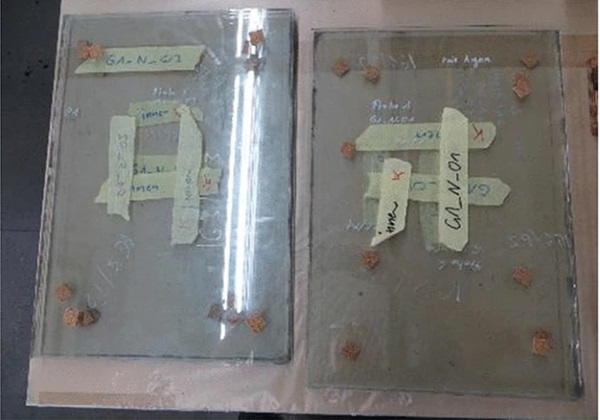
The presence of two distinct edge types allows for the identification of potential influences stemming from edge seal removal, cleaning, and/or sealant residues during subsequent analyses. In total, three different types of glass were prepared from the old IGUs based on the properties of the adhesive surface. Additionally, the glass panes were rotated so that the pane previously facing outward now faces inward towards the cavity. Specifically, this entails positions such as 4 becoming 3, and former position 3 becoming 4 (potentially coated surface 3 facing outward is in this case only for the lab test series).
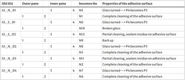
Furthermore, panes with a partially cleaned adhesive surface were utilized, and finally, panes that were completely cleaned (i.e., complete removal of the edge sealant). Table 4 outlines the processing and preparation of the "old" glass, along with their assignment to new insulating glass units. Specifically, the table provides detailed information on which side of the dismantled IGU is paired with a new float glass to form a new insulating glass unit after each treatment.
Table 4 Processing of the old IGU and assignment of the glass to produce new IGUs - Full size table
For example, the two panes of the old insulating glass unit G1_N_01 form part of the two new insulating glass units N5 and N1. N5 comprises the inner pane of the old IGU G1_N_01, rotated so that former position 4 now becomes position 3. The second (outer pane) of G1_N_01 remains unrotated, retaining position 2 of IGU N1.
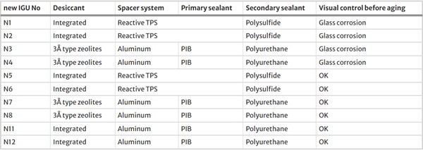
Subsequently, the glass panes prepared as described above underwent further processing into new insulating glass units. For this purpose, an old glass was paired with a new float glass (4 mm thickness) to create a double IGU with an space of 12 mm. In addition to a conventional aluminum spacer with a polyisobutylene (PIB) primary and a polyurethane secondary seal, a reactive thermoplastic spacer (TPS) system in combination with a polysulfide secondary seal was selected as a second edge seal system.
The reactive TPS warm edge spacer system, based on polyisobutylene, replaces conventional edge seal components such as metal or plastic spacer, desiccant, and primary sealant. It consists solely of an integrated polymer matrix incorporating the desiccant. Unlike conventional TPS types, a reactive TPS spacer chemically bonds, rather than just physically attaches, to the glass surface, resulting in a more robust edge compound that withstands various loads, ensuring long-term stability and gas tightness of the IGU as a whole.
Table 5 provides an overview of the further processing of the glass panes into various test units, all with dimensions of 350 mm × 500 mm and assembled in a 4–12-4 configuration. The sealing depth of all insulating glass units, regardless of the secondary sealing material used, was approximately 3.5 mm. For units using the conventional aluminum spacer, the applied amount of butyl per running meter was 2.5 g. For the application of the reactive TPS, a 5.8 mm nozzle was chosen, resulting in a spacer thickness of 6 mm after pressing the IGUs.
Table 5 Overview about the edge compound assembly of the newly produced IGUs - Full size table
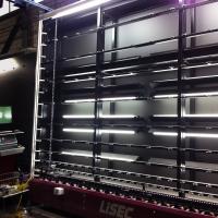
All the aforementioned double glazings were manufactured using a state-of-the-art IG-Line, where a horizontal transport mechanism guides the multi-pane insulating glass through the production process. Initially, the spacer is affixed to the "old" glass pane after it undergoes a fully automated washing procedure with deionized water. The back cover is secured by positioning the spacer on a meticulously adjusted support, movable both vertically and horizontally on one side. Subsequently, the glass with the spacer applied is fed into a press, and the second glass (new float glass) is pressed onto it. Concurrently, inert gas (argon) is introduced into the resulting cavity. Following pressing and filling, the secondary sealant is applied.
To produce units with the conventional aluminum spacer, the initial step involves bending the spacer to match the back overlap, followed by joining corner elements with longitudinal elements and providing connectors with an additional butyl seal. Desiccant is then inserted into the spacers through drilled holes on the back, with only two edges filled. These holes are sealed again with butyl. Subsequently, the spacer surfaces are cleaned, and butyl is applied as the first sealing stage via hot extrusion onto the flanks of the spacers, which are then manually placed onto the glass pane.
In contrast, the reactive thermoplastic spacer (TPS) is applied fully automatically by a CNC-controlled robot directly onto the glass, eliminating any manual steps. The butyl-based material is pumped from drums to the robot head of the applicator at a temperature of approximately 130 °C. This process is optically controlled by a computer with a precision of a tenth of a millimeter. Special patented closing techniques ensure a perfect seal between start and stop. As the application robot follows the glass edge, the spacer material is consistently and precisely positioned.
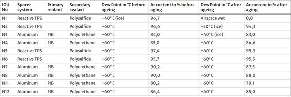
After four weeks of storage under normal climate conditions (23 °C & 50% r.H.), the gas filling degree and dew point were measured to ensure the curing of the secondary seal. All ten newly manufactured test IGUs exhibited a high initial gas filling degree, ranging from approximately 80% to 90% for units with a conventional aluminum spacer and PU secondary sealing, and above 95% for IGUs with a reactive TPS/polysulfide edge compound.
The slightly lower gas filling degree observed in IGUs with an aluminum spacer can be attributed to the manual sealing with PU after transportation from the IG line to the lab. However, this does not indicate a possible leak in the edge seal, as nine out of ten test units exhibited an initial dew point of approximately −60 °C, as expected for a gas and moisture-tight freshly produced IGU. Only test unit N1 showed a slightly increased dew point of −40 °C and the formation of some ice crystals, potentially due to glass corrosion of the old glass used in its construction, leading to adhesion problems and resulting in an untight IGU.
This may indicate production-related issues with the IGU, and the specific causes cannot be precisely identified at this point. The initial results before starting the aging tests are summarized in Table 6.
Table 6 Test results before and after aging tests according to EN1279 part2/3 - Full size table
Next, aging tests according to EN 1279 part 2/3 (DIN EN 1279–2:2018–10, 2018; DIN EN 1279–3:2018–10, 2018) were conducted on all produced test elements, followed by an examination of gas filling level and dew point. Table 6 presents the obtained results, comparing them directly with the initial values.
The post-aging tests yielded positive outcomes for all panes, particularly those where old panes were repositioned to former position 4 within the IGUs (N5-N8). This minimized contamination from old sealant residues resulting in optimal results across various edge seal structures. However, samples (N1-N4), where old polyurethane edge compound was entirely removed, exhibited acceptable residual argon content post-aging. Notably, those with a polysulfide secondary sealant (N1 and N2) showed inferior dew point results, indicating residual polyurethane contamination despite thorough cleaning. This incompatibility led to adhesion issues with the polysulfide sealant, particularly evident in N1, resulting in significant sealant loss and subsequent leakage during aging tests. Conversely, samples with a PU edge seal (N1 and N2) demonstrated better results, albeit with visible adhesion problems in N1. While panes N11 and N12, with incomplete removal of the old edge seal, also exhibited partial adhesion loss, the impact on measurements was less severe compared to N1. Surprisingly, these defects did not significantly affect test outcomes, highlighting the complexities of sealant compatibility and adhesion in remanufactured IGUs (Fig. 15).
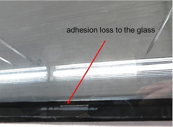
In summary, it appears feasible to construct new insulating glass units (IGUs) from old panes that meet applicable standards. These findings are preliminary and require validation through additional testing. Notably, the functionality of IGUs produced from old glass hinges significantly on the polymer base of the new sealant and the surface quality of the bonding area. Ensuring compatibility between the sealant types used in both original and new units is crucial to prevent adhesion issues. While complete removal of the old edge compound is time-consuming, it is recommended to optimize adhesion. Optimal results were observed when applying the new edge compound to glass from former position 4. Additionally, the quality of the new IGUs is influenced by surface damage such as corrosion or scratches, with variations often observed between weather and room sides. Depending on severity, this damage can impact edge seal adhesion properties.
5 Summary and Outlook
This paper presents ongoing research conducted by the German glass associations BF and FKG on the reuse and remanufacturing of glass panes, with a focus on insulated glass units (IGUs). After establishing fundamental requirements, the authors delve into current research findings, highlighting the potential environmental benefits within the construction industry. Further investigations are suggested to assess the long-term durability of remanufactured IGUs under varied environmental conditions.
IGUs dating back to the 1980s and two units from 2001 underwent disassembly and analysis on various fronts. Initially, gas levels and tightness were examined, revealing no detection of argon in any units using the SparkLike device. Dew point tests indicated varying results based on installation orientation: north-facing IGUs appeared intact, while south-facing units displayed increased dew point temperatures, suggestive of leakage.
Following assessment of IGU functionality, disassembly ensued, with subsequent cleaning of the glass panes. Double ring bending tests conducted on glass panes from two 2001 IGUs revealed no systematic strength reduction. Even on the outer surface of the outer panes, despite heightened roughness, no strength reduction was observed, albeit with a notable number of invalid samples.
The remaining old glass panes were integrated with new coated low-e glass and diverse modern edge compounds to form upgraded IGUs with warm edge technology. Various glass orientations and cleaning levels of the old glass pane were explored. All ten newly manufactured IGUs exhibited a high initial argon gas filling degree of approximately 85–90%. Subsequent IGU tests, including gas level and dew point temperature assessments, were performed according to EN 1279 part 2/3.
While the current findings suggest potential for reusing and remanufacturing old glass and IGUs, the study's sample size remains limited, and results are not yet conclusive. Future investigations, as part of the "Investigations on the Reuse and Remanufacturing of Flat Glass" project (funded by ZukunftBau https://www.zukunftbau.de/projekte/forschungsfoerderung/1008187-2422), aim to expand upon the presented research on a larger scale.

