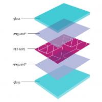
The Paper with the title "A Novel Glass Spacer for Vacuum Insulated Glazing" was first presented at GPD 2017 by Dr Cenk Kocer, University of Sydney, School of Physics, Sydney | NSW Australia 2006.
It consists of two panes of glass separated by a submillimetre vacuum gap, with an array of high strength spacers located in the gap to prevent the glass panes from collapsing under atmospheric pressure. It is well-known that the VIG has the potential to reach thermal conductance levels as low as 0.4 W m-2 K-1.
A crucial part of the VIG which greatly impacts potential thermal performance and underpins ultimate mechanical strength are the spacers. The choice of spacer also greatly affects the production process, cost and the appearance of the VIG product. In this work a novel glass spacer is discussed, with the thermal and mechanical performance of the spacer outlined.
Introduction
The conventional method of reducing heat loss through a single pane window has been to use an insulating window technology, such as double glazed, gas filled, windows where a standard configuration results in a thermal conductance between the inside and outside air of about 1.5 to 2 W m-2 K-1 [1]. A unique alternative technology is the Vacuum Insulated Glazing (VIG). The glazing consists of two panes of glass separated by an evacuated gap, with an array of high strength spacers in the gap used to maintain separation between the glass panes under the action of atmospheric pressure.
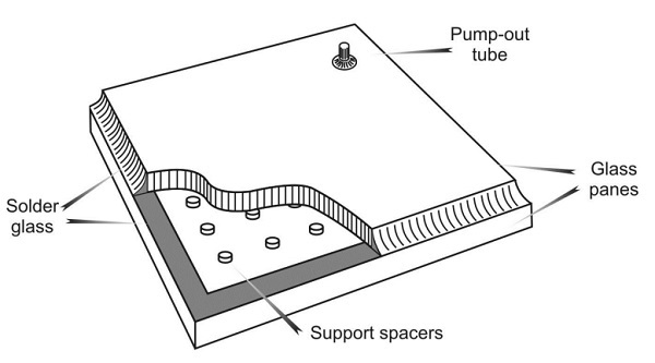
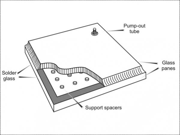
The first successful fabrication of a VIG unit was reported by the Collins group at the University of Sydney (USYD) [2-6]; Figure 1 is a schematic illustration of the USYD design; in this design as-received soda-lime glass panes, where one or both the panes are coated with a low emittance coating, are used, and the array of high strength spacers are cylindrical in shape and typically 0.5 mm in diameter and 0.2 mm in height. The two glass panes are hermetically sealed using a solder glass (glass frit) over the perimeter of the panes, and a pump-out tube on the top glass pane is used to evacuate the internal gap.
Heat flow through the VIG is due to, 1. conduction through the spacer array, 2. radiation between the internal surfaces in the vacuum gap, and 3. conduction through the solder glass edge seal; we assume the internal vacuum is low such that residual gas conductance is essentially zero. The overall heat transport for a window unit is typically given as the air-to-air heat conductance (or U-value).
To determine the U-value the heat transfer coefficient from the surfaces of the VIG to the inside and outside environments must be defined, and in this work we will use 8.3 W m-2 K-1 and 30 W m-2 K-1, respectively, where the inside and outside temperatures are defined as +21.1 °C and -17.8 °C, respectively. These values are taken from the ASTM standards and were also employed in past works [5].
The detailed formulations for the different heat transfer pathways are not given here as a matter of brevity, they have been reported in detail in previous publications [2-6]. It is important to note that the thermal conductance of VIG is not strongly dependent on the glass thickness. The thermal conductance is dominated by the surface-tosurface radiation between the glass panes and the conductance of the spacer array.
![Figure 2: A plot of the VIG centre-of-glazing, air-to-air thermal conductance as a function of the combined surface emittance, for different combinations of the radius of the spacer and the spacer array separation (equivalent to the total number of spacers in the gap). The combined emittance is elucidated in inset table; ε = 0.84 is for soda-lime glass with no coating, ε = 0.2 for a conventional low emittance coating, and ε = 0.03 for a high performance low emittance coating [16].](/sites/default/files/inline-images/Fig2_80.jpg)
Figure 2 is a plot of the VIG centre-of-glazing, air-to-air, thermal conductance as a function of the combined surface emittance, for different combinations of the radius of a spacer and the array separation (the distance between the spacers). What is particularly highlighted in figure 2 is the importance of the low emittance coating. Nevertheless, to reduce further the U-value of the VIG it is the spacer array contribution that is of most interest.
Clearly, to reduce the overall VIG U-value through reductions in the spacer array, a reduction is needed in the thermal conductivity and/or the size and/or the number of spacers. For each option the critical issue is one of strength; reducing the diameter of contact produces high levels of bulk compressive stress in the spacer and high levels of surface stress in the underlying glass, and a lower number of spacers (equivalent to increasing the distance between spacers) results in higher forces on each spacer and a greater stress in the glass.
Spacer Design Implications
The resistance to heat flow through a single spacer is related to; 1. the constrained flow that occurs because of the relative size difference between the supported glass area and the area of the spacer where this term is known as the spreading resistance, and only depends on the spacer size and the thermal conductivity of the glass and 2. the thermal resistance of the material of the spacer, which is determined from the length, area and thermal conductivity of the spacer material. The total resistance to spacer heat flow is then the series sum of these two terms and is expressed as,

where r is the radius of the spacer, h is the height of the spacer, kglass and kspacer are the thermal conductivities of the glass and spacer, respectively [6,7,9]. Typically, for a spacer produced from a metal, such as stainless steel, the thermal spreading resistance dominates the conductance, and therefore, it is only the thermal conductivity of the glass, the radius of the spacer, and the number of spacers which determines the total contribution of the spacer thermal conductance.
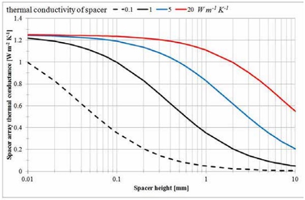
Figure 3 is a plot of the total contribution of the spacer array thermal conductance as a function of the spacer height, for different thermal conductivity values of the spacer material. Clearly, there is an advantage in producing spacers from materials of low thermal conductivity, if the thermal conductivity is less than 5 W m-2 K-1.
As mentioned, the changes that can be made to the spacers and the spacer array dimension provide a significant impact on reducing the overall U-value of a VIG. Assuming that the edge seal of a VIG is well formed to reduce the local stresses to levels below the critical point of long term glass failure, the dominant changes of interest are directly related to the spacers; 1. compressive stress in the spacers, 2. the stress on the glass surface due to indentation of the spacers, and 3. the deformation of the glass between the spacers, which produces tensile stresses above spacers on the outside surfaces of the glass panes.
Each of these stress fields is at a level that is directly related to the spacer shape, size, and distance of separation in the array. Table 1 presents the basic formulas that provide a good criterion for the potential failure of material due to these stress fields; the derivation and implications of these formulas is discussed in detail in the literature [6,9,10].

In each case it is assumed that for long term (+25 yrs) loading of the glass, the magnitude of stress should not exceed 8 MPa; this criterion of stress is taken from the ASTM standard. The allowable stress level in the case of indentation of the spacers is not determined in the same way. The indentation process is further complicated due to the high gradients of the stress at the edge of the spacer contact [11,12]. Typically, the spacer can be produced from a stainless steel, such as type 304, which as a cylindrical spacer can exhibit a yield strength of about 1- 2 GPa.
Clearly, the choice of spacer material, shape, size (height), and the spacer array design will play a significant role in defining the thermal and mechanical performance of a VIG unit. There are, however, other issues that must be considered. First, is the production of the spacer; good tolerances in size and shape must be adhered to; otherwise, localised differences in the forces and stresses may produce undesirable failures over long service lifetimes.
In addition, this may impact on the visual appearance of the spacer array. Second, it is a non-trivial exercise when placing the spacers on the surface of the glass panes in manufacturing, where speed and accuracy will have significant knock on effects.
If the placement process is slow the production costs will increase, and if accuracy is not well defined, as mentioned, localised differences in the forces and stresses may produce undesirable failures over long service lifetimes, not forgetting undesirable visual effects. It is important to optimise the choice of the spacer parameters not only for VIG performance, but also the performance and reliability of the manufacturing process of the spacer and ultimately the VIG unit.
In the following sections the detail of a novel spacer is presented. The spacer is not an independent component, in great contrast to traditional spacer designs; the spacer is produced on the glass surface and is a part of the glass pane. A method of laser irradiation is used to heat a local volume of the underlying glass pane. The heating process takes the glass to temperatures over 900°C for short periods, typically 1-2s. This process was invented at Corning Inc. USA [14,15].
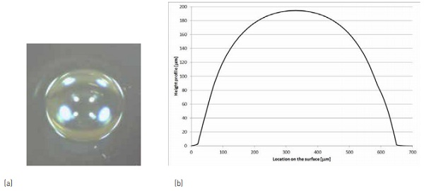
Since the heated volume is confined by the surrounding mass of cold glass, it expands at the surface creating a surface feature that is spherical in shape. Figure 4a is an image, top view, of the surface feature produced on the glass surface. Figure 4b is a surface profile of the surface feature.
This process has been demonstrated on several glass types [15], with the latest development including application of the process on as-received soda-lime float glass. In producing a surface feature on the glass surface that can be a spacer element, significant advantages can be gained in relation to several of the critical design issues mentioned above. The laser spacer, as it is termed in the remainder of this paper, can provide an advantage in the underlying lower thermal conductivity. It is in the following sections that the measurement of the total thermal conductance and the ultimate strength of the laser spacer are presented.
The Thermal and Mechanical Performance of the laser spacer
As presented previously, figure 3 is a plot of the analytical solution of the total array thermal conductance for a typical cylindrical spacer. The plot highlights the advantage of increasing the height or decreasing the thermal conductivity of the spacer. Even though the laser spacer can be produced at different heights, it is the advantage of the lower thermal conductivity that is of interest.
The data indicates an approximate 30% decrease in the total spacer array thermal conductance, when considering the difference between what would be a metal spacer and the laser spacer. To confirm that this is in fact the case, measurements on the laser spacers were performed. At the University of Sydney a small area guarded hot plate (GHP) was developed for measuring the thermal conductance through a single spacer [7].
Clear soda-lime float glass sheets, at a size of 350x350 mm, with an array of laser spacers were obtained from Corning Inc. USA [16]. These glass panels were then used to construct VIG units, the spacing of the array was 20 mm and the spacers were spherical in shape, about 180 µm in height and 600 mm in diameter at its base.
Measurements were taken on several of the laser spacers and at several points between the spacers. In these samples the glass was not coated with a low emissivity coating and the unit was prepared with an internal volume pressure below 10-3 Torr; at this pressure the residual gas thermal conductance is at a level of 0.01 W m-2 K-1 or less.
As mentioned previously it is important that the spacer used in a VIG be strong since there is not only the continuous load of atmospheric pressure, but also the potential of additional forces on a spacer due to external loads, such as thermal and wind loads. At the University of Sydney a simple and effective lever apparatus has been developed. Into the apparatus a single spacer, sandwiched between two small glass sheets, of size 30x30 mm, can be placed under load.
Relative to the spacer the applied load can be a combination of a normal and shear load, up to a limit of about 500N. For these measurements 30x30 mm, 4 mm thick, glass coupons with a single laser spacer, located at the centre of the coupon, were obtained from Corning Inc. USA [16].
During typical measurements the load sequence on the spacer was continuously imaged and the load at the spacer was measured using appropriately placed load cells. In all tests the load on the spacer was applied at low rates and care was taken to identify all levels of damage. In general, regardless of the spacer type (that is, cylindrical or spherical shapes), as long as the contact area of the spacer is equal, the contact surface of the glass substrate will exhibit failure at the same normal/ shear load combinations; cylindrical and spherical contacts, of the same contact area, exhibit a negligible difference in the contact surface stress [11,12].
It was not the focus of this work to characterise the failure limit of the underlying glass material. The object of the test was to determine the loads at which damage and/or failure of the spacer is observed, and thus, define simply the strength of the spacer. In all cases the glass was prepared to condition the surface to provide a contact friction as would be expected within the vacuum environment of the internal volume of the VIG.
As the applied load on the spacer is increased the contact area also increases, and follows well the analytical contact mechanics definition of a spherical contact on a flat surface [11,12]. In the analysis of the measurement data the linear elastic properties of glass-on-glass contact was taken into consideration. The laser spacer contact measurement was performed on as-received glass, thermally tempered glass, and on a Sapphire substrate.
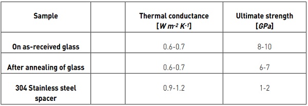
Table 2 presents the results for a laser spacer that was produced on as-received sodalime glass, and also results for the same spacer sample that has been annealed at a temperature of 600°C for 1 hr. In the case of the thermal conductance, a typical sample, of uncoated glass, provided a measured surface-to-surface thermal conductance of approximately 3.8 W m-2 K-1.
On the same VIG sample the thermal conductance of the array of spherical laser spacer was measured to be approximately 0.66 W m-2 K-1, which is in good agreement with the analytical calculation result of 0.6 W m-2 K-1. It is important to note that under the action of atmospheric pressure the contact radius of the laser spacer was about 0.18 mm during the measurement of the thermal conductance.
The data provided in figure 3 was calculated for a spacer with a cylindrical contact radius of 0.25 mm. As mentioned previously, the advantage of the laser spacer in addition to a potentially smaller contact area, is the underlying lower thermal conductivity. Considering all parameters equal except for the thermal conductivity, the advantage for the laser spacer is about a 30% decrease in the total thermal conductance contribution as compared to that of a metal spacer array.
Even though the thermal conductance of the laser spacer is lower because of the underlying lower thermal conductivity, in most cases the fact that the spacer is glass would be a concern in terms of ultimate strength. Under an increasing applied load the laser spacer exhibited a much higher ultimate strength than expected. It is reasonable to suggest that the laser process has resulted in a significant structural change; of which one part is a level of residual stress (temper) that has been locked into the structure. Typically, the force on a spacer due to atmospheric pressure increases as the array spacing is increased: that is, at a spacing of 20 mm the force is 40N, at 30 mm it is 90N and at 40 mm it is 160 N.
The ultimate strength of the spacer was measured to be at an applied load of about 500-600N. This translates to a mean contact pressure (compressive stress) of about 8 – 10 GPa. At the point of catastrophic failure, the fracture of the spacer exhibits fragmentation that is similar to that observed in thermally tempered glass sheets. This is shown in figure 5, an image of a coupon sample from the side. A simple test was performed to observe a change in the temper of the spacer. A coupon sample was annealed at 600°C for 1 hr.
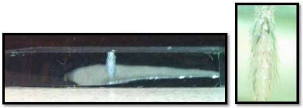
The annealed laser spacer exhibited a negligible change in size and shape, and when loaded to failure, the ultimate strength decreased by about 25-30%. Interestingly, the previously observed fragmentation did not occur. Figure 6 is an image of an annealed coupon sample from the side, after failure. The spacer has disintegrated under load, with very little through thickness fragmentation. that was annealed at 600°C for 1 hr, after catastrophic failure.

Summary
The Vacuum Insulating Glazing (VIG) is a highly insulating technology that has the potential to have a significant impact on energy use in buildings. The ultimate thermal conductance of the VIG is strongly dependent on the number, shape, and size, of the spacer array.
The use of a method to produce a spacer on the surface of the glass pane, by using the underlying glass as the material for the spacer, produces an advantage in the lower thermal conductance of the spacer. Measurements performed show that this advantage in the lower thermal conductance is about 30%. Furthermore, even though the laser spacer is glass, the processing of the glass to form the spacer results in structural changes which lead to a higher ultimate strength.
In this paper the background information and the initial thermal and mechanical measurements of a laser spacer were presented. Further work has been performed to detail the characteristic behaviour of shape changes, shear load effects, application in panel size strength tests, and integration of tempered glass.
In addition, numerical modelling to systematically detail the physical processes that govern the behaviour of the spacer has been undertaken. In future articles these results will be presented to provide a complete picture of the use of a laser spacer in the construction of a VIG device.
References
[1] D. Arasteh, S. Selkowitz, and J. Wolfe, The design and testing of a highly insulating glazing system for use with conventional window systems, Journal of Solar Energy Engineering, 111, 44-53, 1989.
[2] R. E. Collins et al., Vacuum glazing – A new component for insulating windows, Building and Environment, 30[4], 459-492, 1995.
[3] T. M. Simko et al., Temperature-induced stresses in vacuum glazing: Modeling and experimental validation, Solar Energy, 63[1], 1-21, 1998.
[4] R. E. Collins et al., Transparent evacuated insulation, Solar Energy, 49[5], 333-350, 1992.
[5] R. E. Collins et al., Current status of the science and technology of vacuum glazing, Solar Energy, 62[3], 189-213, 1998.
[6] C. F. Wilson et al., Heat conduction through the support pillars in vacuum glazing, Solar Energy, 63[6], 393-406, 1998.
[7] C. J. Dey et al., Design and validation of guarded hot plate instruments for measuring heat flow between evacuated plane-parallel glass surfaces, Review of Scientific Instruments, 69[8], 1998.
[8] H. Manz et al., Triple vacuum glazing: Heat transfer and basic mechanical design constraints, Solar Energy, 80[12], 1632-1642, 2006.
[9] R. E. Collins and A. C. Fischer-Scripps, Design of support pillar arrays in flat evacuated windows, Australian Journal of Physics, 44, 73-86, 1991.
[10] A. C. Fischer-Cripps et al., Stresses and fracture probability in evacuated glazing, Building and Environment, 30[1], 41-59, 1995.
[11] R. Mouginot and D. Maugis, Fracture indentation beneath flat and spherical punches, Journal of Materials Science, 20, 4354-4376, 1985.
[12] R. Mouginot, Crack formation beneath sliding spherical Punches, Journal of Materials Science, 22, 989-1000, 1987.
[13] Q-C. Zhang, T. M. Simko, C. J. Dey, R. E. Collins, G. M. Turner, M. Brunotte, A. Gombert, The measurement and calculation of radiative heat transfer between uncoated and doped tin oxide coated glass surfaces, International Journal of Heat and Mass Transfer, 40[1], 61-71, 1996.
[14] A. Streltsov, et al., Laser texturing of doped borosilicate glasses, Proc. of SPIE Vol. 7584 75840S3, 2010.
[15] S. Loguno, et al., Laser-induced swelling of transparent glasses, Applied Surface Science, [257], 2011.
[16 ] Dr Alexander Streltsov, Corning Research & Development Corporation, Sullivan Park, SPAR-02-05, Corning, NY 14831


