Article Information
- Digital Object Identifier (DOI): 10.47982/cgc.9.628
- Published by Challenging Glass, on behalf of the author(s), at Stichting OpenAccess.
- Published as part of the peer-reviewed Challenging Glass Conference Proceedings, Volume 9, June 2024, 10.47982/cgc.9
- Editors: Christian Louter, Freek Bos & Jan Belis
- This work is licensed under a Creative Commons Attribution 4.0 International (CC BY 4.0) licence.
- Copyright © 2024 with the author(s)
Authors:
- Hoessein Alkisaei - Delft University of Technology, Faculty of Civil Engineering and Geosciences
- Hanna Heller - Delft University of Technology, Faculty of Civil Engineering and Geosciences
- Clarissa Justino de Lima - American Glass Research
- Chris Noteboom - Delft University of Technology, Faculty of Civil Engineering and Geosciences
- Christian Louter - Delft University of Technology, Faculty of Civil Engineering and Geosciences

Abstract
Brazil has a low percentage of recycled container glass due to multiple factors, such as inadequate waste collection and recycling infrastructure, low public awareness about recycling's significance, and insufficient laws to promote it. In addition, the country faces high levels of homelessness and inadequate housing. As a result, an increasing number of builders are exploring repurposing glass bottles as a construction material for walls, occasionally incorporating them into traditional earthen building techniques. Therefore, this paper investigates the potential of prefabricated earthcrete bricks that integrate glass container bottles for the construction of structural load-bearing walls for affordable housing in Brazil while at the same time reducing pollution, enhancing aesthetics, and promoting environmental friendliness. Initially, the mechanical behaviour of the container glass bottles in earth bricks is investigated through FEM modelling. Subsequently, prototypes are made and tested in the laboratory, revealing a compressive strength between 8.21 and 11.40 MPa. From these findings, it is concluded that reusing glass bottles for the construction of structural walls capable of supporting small-scale structures could be feasible.
1.Introduction
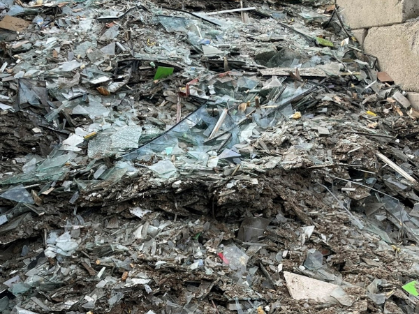
Many countries in the world still have a low percentage of recycling glass. This is due to a lack of proper waste collection and recycling infrastructure, insufficient public awareness about the importance of recycling, and a lack of adequate laws and regulations to promote recycling.
Brazil produces 8.6 million tons of glass annually, of which it is estimated that 630.000 tons are beer bottles and only a mere 300.000 tons are recycled (Brazil Sustainable Industry 2022; MassFix 2024). The remaining tons end up in landfills or are dumped in nature. In addition, Brazil faces a high level of homelessness and inadequate housing. Housing for low-income families has drastically decreased.
Therefore, builders are exploring repurposing glass bottles as a construction material to construct walls, occasionally incorporating them into traditional earthen building techniques. This approach provides the opportunity to construct affordable houses while tackling pollution at the same time. Some examples from practice are the following.
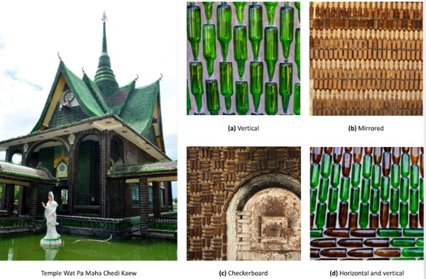
The Wat Pa Maha Chedi Kaew, also known as the Temple of a Million Bottles, is a Buddhist temple situated in Khun Han, Thailand, see Fig. 1 (Wat Pa Maha Chedi Kaew 2024). After becoming increasingly aware of the detrimental impact that numerous discarded bottles were having on the environment, the monks utilised the collected bottles as decorative and construction materials and were able to save both money and valuable resources. To ensure structural integrity, the bottles are firmly affixed to one another using cement. Not only the scale of the temple stands out, but also the innovative placement, positions and configurations of the bottles within the walls of the temple. A visual representation of these various configurations can be observed in Fig. 1.
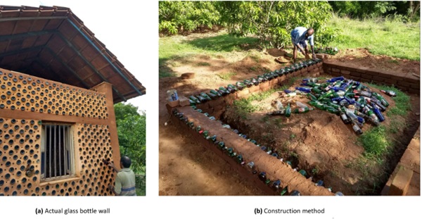
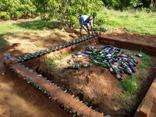
Another example is the beer bottle house in Tamil Nadu, India (All About Architecture 2021), see Fig. 2. The plot has a total size of 3x4 metres and the walls consisted of two layers of bottles that were arranged perpendicular to the wall, alternating their orientation. The spaces between the bottles are filled with a mixture of cement and locally sourced soil, serving as mortar to hold them firmly in place.
While several examples exist in practice, the building techniques and codes for the reuse of glass bottles in earth-based buildings are underdeveloped. In addition, there is a shortage of skilled builders and limited educational resources dedicated to these methods. Challenges for building techniques include difficulties in constructing straight walls due to the bottles’ asymmetric and round shapes. These round and complex shapes also complicate mortar connections, leading to gaps and a lack of a uniform building technique. Also, underdeveloped building codes in combination with lacking comprehensive testing for performance evaluation make building techniques susceptible to vulnerabilities. It is therefore paramount that the challenges are addressed and the building techniques and codes are improved.
When thinking about the practicalities of building an actual wall made out of glass bottles, the question arises of how to ensure the structural feasibility of a wall that consists of repurposed glass bottles and an earthen mixture. Therefore, this research aims to add to closing the knowledge gap by addressing the following subquestions:
- How can a load-bearing masonry unit be developed by combining repurposed container glass (as a whole) with an earthen mixture?
- How should the glass bottle(s) be positioned within the Glass Bottle Earth Brick (GBEB) to maximise its strength?
- What is the strength of a single GBEB consisting of glass bottles and an earthen mixture?
- What limitations would a GBEB, consisting of repurposed glass bottles and an earthen mixture, have?
This research aims to answer the aforementioned research questions by producing multiple earthen bricks that contain a single or more glass bottles. These bricks are tested physically, which will provide valuable information. Consequently, numerical analyses of these bricks are executed using the Finite Element Method. Ultimately, the results from the numerical analyses will be compared to the results of the physical experiments for validation, making it possible to draw conclusions and pave the way for further research.
2. Methods
2.1. General Methodology
This section presents the applied methods that help obtain the required data to answer the aforementioned research questions. This includes the methodology of constructing a physical prototype, Finite Element Method simulations that predict the behaviour of the physical prototypes, and the actual set-up and execution of physical experiments that help generate an understanding of the mechanical behaviour of the physical prototype and validate the numerical findings.
Moreover, after thorough literature research and investigation of contemporary methods, a list of requirements for a ‘Glass Bottle Earth Brick’ (GBEB) is composed. Note, this list is not sorted in a particular order:
- The glass bottle(s) should be visible. The visually aesthetically pleasing aspect is a main motivator for people to repurpose glass bottles. The bottles are placed horizontally, ensuring light passes through the bottom, with the additional benefit of being easily stackable.
- The labels on the glass bottles should be removed to ensure bonding with the mortar.
- The GBEB should be producible without the use of expensive machinery. When prefab components are produced, they should have certain dimensions and weights that are easily handled with body strength.
- The load-bearing Glass Bottle Earth Wall (GBEW), which consists of GBEBs, should fulfil serviceability and ultimate limit state requirements.
- The load-bearing wall should have the possibility to consist of prefabricated GBEBs to increase its flexibility in space and time.
For this research, the applied method for the construction of a GBEB is inspired by the pre-cast glass bottle panels by Mud Hands (Mud Hands 2014). However, slight adjustments are made for this research. The application by Mud Hands places bottles inside a mould after which concrete is poured as strengthening and bonding material. Subsequently, the bottles are cut at shoulder height, leaving the body and the bottom of the bottle encased within the concrete.
For this research, an earthen mixture will be used instead of concrete. Secondly, the bottles will be used in their entirety, meaning that no parts of the bottles will be chopped or cut off. Thirdly, Mud Hands uses a single generic and standard pattern for the placement of the bottles, while in this research different bottle patterns are investigated as well. Lastly, the GBEB will have dimensions and a weight that allow for easy handling without the usage of expensive machinery.
2.2. Earthen mix
The objective is to create a self-compacting earth-based composite from local earth that will be utilised to construct a brick in which glass bottles will be cast. Several research efforts have been made to give earth-based materials similar properties to that of concrete, to enable casting and enhance their competitiveness in relation to other construction materials (Clausell et al. 2021; Cong and Chen 2016; Gomaa et al. 2022; Landrou et al. 2016; Matos and Varum 2022; C. Ouellet-Plamondon and Habert 2014; C. M. Ouellet-Plamondon and Habert 2016). This contributes to the wider acceptance of earth as a viable construction material, given the familiarity with concrete in construction practices.
For this research, the focus has been placed on the following aspects of the mixture:
- The mixture should not show any segregation.
- The flow diameter is aimed to be between 200 and 300 mm to ensure it can self-compact and easily flow between the bottles.
- The mixture should be demouldable after at least 24 hours of casting.
- The failure pattern should have a similar satisfactory failure pattern as that of concrete.
- Early signs of excessive shrinkage (crack forming) are not favourable.
The applied soil for this study is Dutch soil that originates from Emmen, a place in North East Netherlands. The clay is extracted by OSKAM V/F (Compressed Earth Block Machines en Leem producten 2024) from road construction and construction pits. It is then processed without heating so that the clay quality is retained in the products. Consequently, the soil is mixed and large clumps are removed or crushed.
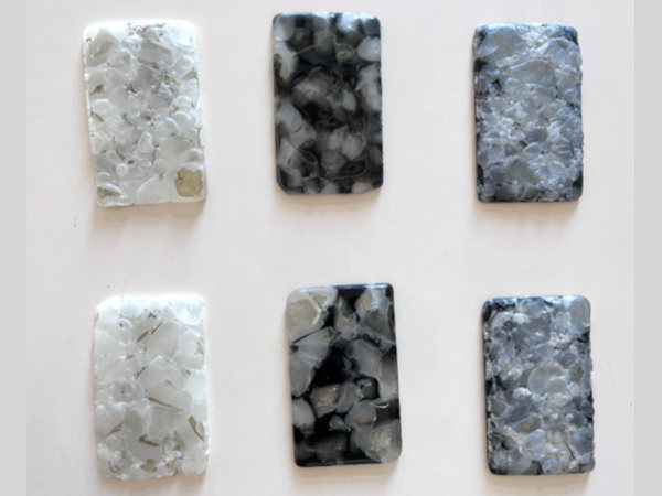
For this research, five different types of earth-based mortar mixtures with different compositions were created. The proportions of the mixtures are informed by a comprehensive review of existing literature, as documented by (Clausell et al. 2021; Cong and Chen 2016; Gomaa et al. 2022; Landrou et al. 2016; Matos and Varum 2022; C. Ouellet-Plamondon and Habert 2014; C. M. Ouellet-Plamondon and Habert 2016). In addition, valuable insights are retrieved from experts in the field. The mixtures are made in batches of 1.2 L using a Hobart Type N-50 mixer. All dry components (soil and cement) are added together and mixed at a slow speed. During the process, it is made sure that the sides and the bottom are mixed properly. After a good mixture, approximately 75% of the superplasticizer is added to the mix. Once that is mixed properly, the remaining 25% of the superplasticizer is added.
The first three mixtures (A1, A2, A3) are artificial soils composed of components as depicted in Tab. 1. The latter two mixtures (N1, N2) are natural soils. The proportions of all five mixtures are presented in Tab. 2. The latter table also illustrates the main ratios within the mixture design, where the category fines integrate the clay and silt content of the soil with cement and limestone filler. Consequently, all five soil mixtures are physically experimented as presented in Tab. 3. The results from the flexural and compressive tests are presented in Tab. 4 and 5 respectively.
Table 1: Composition of Artificial Soil.
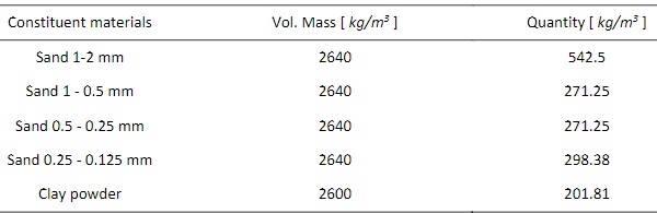
Table 2: Mixture proportions of Earth-Based Mortar with artificial soils (A1, A2, A3) and natural soil (N1, N2).
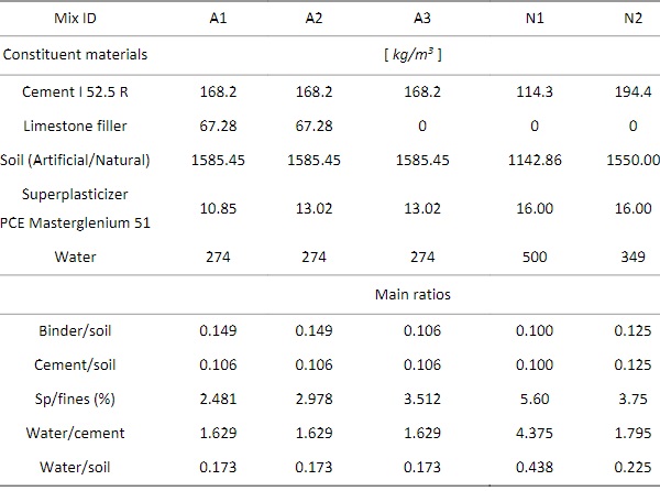
Table 3: Experimental program.
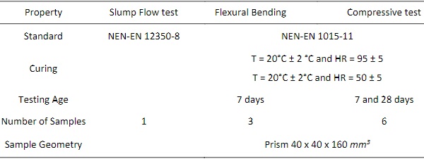
Table 4: Flexural tensile strength test results after 7 days (NEN-EN 1015-11, Stevinlaboratory TU Delft, H. Heller).
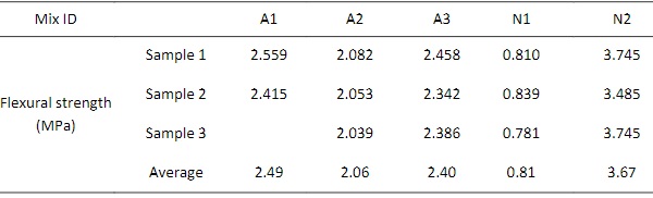
Table 5: Compressive strength test results after 7 and 28 days of curing (NEN-EN 1015-11, Stevinlaboratory TU Delft, H. Heller).
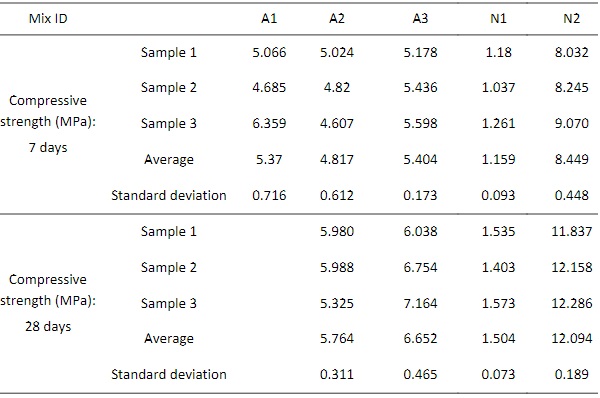
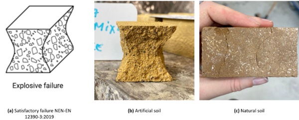
From the comparison between A1 and A2, it became evident that the superplasticizer has a negative effect on the flexural tensile strength. On the other hand, the compaction is higher with the addition of a superplasticizer. From the comparison between A2 and A3, it became clear that decreasing fines has a positive impact on flexural strength. As a result, it is decided to remove the limestone filler in the final mix with natural soil. In addition, Fig. 3 presents failure patterns that have a satisfactory similarity with that of concrete. Ultimately, mixture N2 was chosen to be applied for this research.
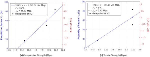
The characteristic compressive and tensile strength for mixture N2 are equal to 11.77 and 3.42 MPa respectively, see Fig. 4. Fig. 4(a) presents the compressive strength after 28 days, while Fig. 4(b) presents the tensile strength after 7 days. A Weibull linear regression is plotted through these points to estimate the characteristic strength with a failure probability of 5%. Note that the sample size is relatively small and accuracy can be improved by enlarging the sample size.
2.3. Longneck Beer Bottle Casted in Earth-Based Mortar
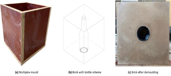
Three Glass Bottle Earth Bricks (GBEBs) are made with each brick casting one bottle which is bound by mortar made of mixture N2. To produce a brick, a mould is crafted using multiplexes as depicted in Fig. 5(a). To facilitate an effortless demoulding process, a thin layer of oil is uniformly applied to the interior of the multiplex mould. The Longneck beer bottle is positioned vertically at the centre of the mould, see Fig. 5(b). Next, the earth-based mortar is prepared, as described in previous sections, and poured into the mould. To prevent the bottle from floating upwards a weight is placed on top of the bottle. The brick undergoes a curing process at ambient temperature and is subsequently demoulded after a 24-hour duration, see Fig. 5(c).
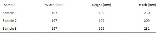
The dimensions of the three GBEBs are given in Tab. 6. The glass bottle utilised in this experimental setup is retrieved from Brouwland with surface conditions mildly abraded.
Table 6: Sample geometry of brick with a longneck beer bottle.
A notable gap exists in understanding how the earth-based mortar and the container glass interact to form a whole GBEB. To bridge the existing knowledge gap, a compressive strength test is executed, to uncover the complexities of their behaviour, identify the failure load and failure mode, and potentially draw insightful conclusions from the observed failure patterns.
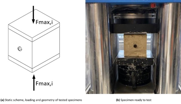
The compressive strength tests are conducted on each specimen after 28 days of curing. The rate of compression is taken to be 6 kN/s and the test will automatically stop when no strength increment is measured. Fig. 6 presents the setup of the experiment.
2.4. Numerical Analysis of Glass Bottle Earth Brick
To obtain deeper insights about the behaviour of a GBEB the Finite Element Method (FEM) is employed. This investigation aims to provide valuable perspectives on potential failure modes, the impact of bottle orientation, and the effect of varying internal distances between the glass bottles. The findings from the physical experiments are compared with the results from FEM analyses for validation.
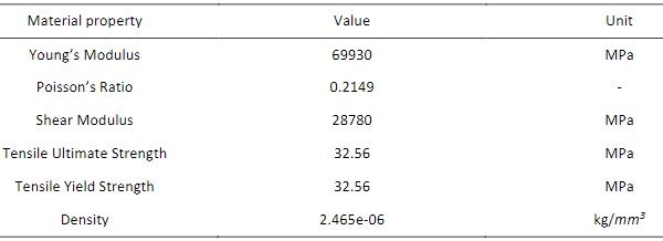
The assigned material properties of the glass bottles are equal to those of soda-lime glass. The estimated and applied material properties for the earthen mix are presented in Tab. 7. Since Earth Based Mortar is a recent invention, assumptions have been made where there is limited understanding of its material properties and are denoted by an asterisk (*). Assumptions have been based on existing data on rammed earth and low-strength concrete since Earth-Based Mortar (EBM) showed similar failure patterns as that of low-strength concrete. The Poisson ratio of the earthen mix is set equal to 0.2, characterising dry earth conditions. For the Elastic Modulus, a value of 25000 MPa is chosen, which is significantly influenced by the earthen mix and the moisture content. Higher Elastic Moduli correspond with higher peak stresses.
For the numerical analysis, the software package of SolidWorks is used. The FEM Analysis follows a linear elastic approach with properties as presented in Tab. 7 and 8.
Table 7: Estimated material properties of EBM.
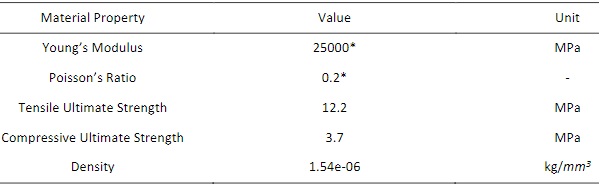
Table 8: Material properties of an abraded Longneck Beer Bottle.
The 3D FEM model of the GBEB is modelled, as depicted in Fig. 7. In addition, boundary conditions are applied on the upper and lower surfaces resembling the physical experiments. An externally prescribed downward displacement of 0.1 mm is placed on top of the modelled GBEB.
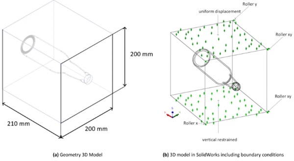
The collaborative numerical behaviour between the earthen mix and the glass bottle is ensured via the use of interface conditions. The interface condition is characterised by the utilisation of the Mohr-Coulomb model. A coefficient of friction is implemented to account for the internal friction of both the bottle and the earthen mix.
The relatively complex geometry, the small edges, the curvatures, the slender features and the acute corners of the glass bottles demand a mesh quality that can successfully reach convergence during analysis. For high and low-quality mesh are triangular shell elements and 3D tetrahedral solid elements used, respectively. By applying a blended curvature-based mesher the element size adapts to the local curvature of the geometry. This approach can overcome mesh failure.
Knurls are the ridges located on the base of a glass container. Knurling serves to separate damage created during the normal handling of containers from the highly stressed area of the bearing surface. The FEM model does not include the knurls. It remains unclear whether knurls have a significant effect on the ‘total’ behaviour of the glass bottles or the GBEB in its entirety. However, the research of Dr. Hu demonstrates that the stresses between the knurls increase by 43% when a glass bottle is exposed to external loads (Hu 2022).
3. Results
3.1. Compressive test results of GBEBs
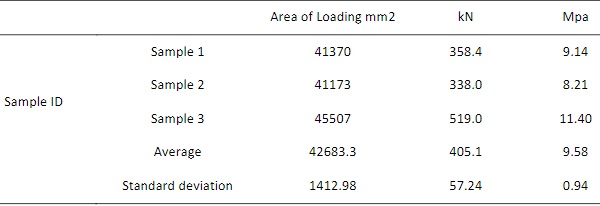
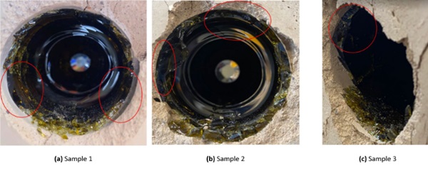
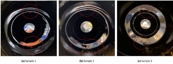
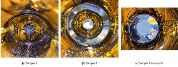
The results of the compressive experiments are presented in Tab. 9. The three GBEBs that have been excited to compressive experiments presented similar behaviour and failure patterns. Firstly, all the samples displayed circumferential failures at the heel region, which forced the heel to ‘fall out’ during the experiment. This is depicted in Fig. 8. Areas circled in red indicate zones of tensile stress intensification. Secondly, each GBEB exhibited cracks along the side of the bottle on the inner glass surface, as presented in Fig. 9. The cracks result from tensile stresses in the orthotropic direction on the inner side of the bottle. Thirdly, flash photography revealed cracks on the outer surface of the bottle, which align with the direction of cracks on the inner side of the bottle but along the horizontal line of the cross-section. This is presented in Fig. 10. Lastly, Fig. 10 also depicts vertical cracks at the shoulder-to-neck transition.
Table 9: Results of compressive test of earth bottle brick samples.
To determine the fracture origin location, the fracture origin orientation, and fracture mirror dimensions an optical microscope was utilised at magnifications up to 60X. In addition, a scanning microscope (JEOL JSM-IT510LV) equipped with X-ray spectroscopy capabilities was used to image the fracture origins at even higher magnifications and to identify any residues.
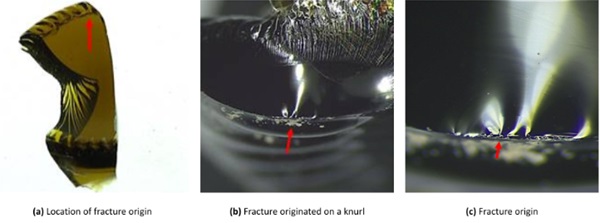
For Sample 1 it was not possible to determine the fracture origin. For Sample 2, the fracture origin was located at the lowermost heel region of the bottle, which is just above the bottom/bearing surface. This region is indicated with red arrows in Fig. 11. For Sample 3, the origin of the fracture was located at a knurl on the bearing surface. The location of this fracture origin is with red arrows indicated in Fig. 12.
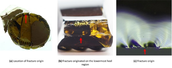
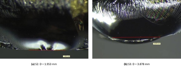
Fracture mirrors in Samples 2 and 3 were spotted, which enables the calculation of the stress at failure by using Eq. (1), in which r equals the radius of the fracture mirror in cm as illustrated in Fig. 13. The calculated stresses for Sample 2 and 3 are approximately 59.62 MPa and 42.27 MPa, respectively.
![]()
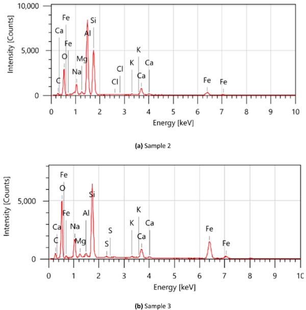
Moreover, Samples 2 and 3 have been subjected to scanning with an electron microscope with energy dispersive X-ray spectroscopy (SEM/EDS) to check whether any metal residue at the fracture origin would be present, which indicates a possible cause for the cleavage scratches. Cleavage scratches result from the translation of a hard and sharp object across the glass surface under an increased normal load.
Results from the scanning indicate that in Samples 2 and 3 metal residue composed of increased amounts of iron (Fe) and aluminium (Al) is present, as shown in Fig. 14. The presence of other elements, like Ca, Na, Mg and Si, is expected in typical container glass compositions.
The results from determining the fracture origin and its characteristics indicate that abraded glass bottles have a lower threshold for failure.
3.2. Numerical analysis results
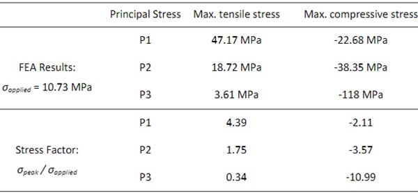
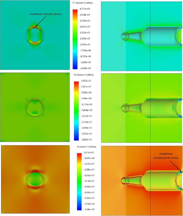
The results from the numerical FEM analysis are presented in Tab. 10 with P1, P2 and P3 representing the principal stresses. Due to linearity, the stress factor is derived by dividing the peak stress σpeak by the applied external stress σapplied. The corresponding deformed results are depicted in Fig. 15 with arrows indicating the maximum and minimum stress distributions.
The results of the numerical experiments coincide well with the obtained results from the physical experiments. For example, tensile stresses predominantly occurred on the inside surface of the bottle. In addition, compressive stresses are anticipated as well on the inside surface of the bottle. However, while cracks do not appear on the inside surface of the bottle, they do exist on the outside surface. In conclusion, numerical simulations show that the GBEB, as shown by the physical experiments, fails at the base and bottom of the glass.
Table 10: FEA Results of Principal Stresses, Referring to Laboratory Performance of Bricks.
4. Discussions and conclusions
This research focused on the incorporation of glass bottles into earth-based constructions, because of their mutual advantages of environmental sustainability and cost-effectiveness. Typically, in walls with glass bottles, the bottles are arranged horizontally creating a captivating effect where light filters through the bottles. However, irregular shapes of glass bottles pose challenges when connecting them with mortar during wall construction. In addition, it is expected that the orientation of the integrated container glass bottles have a significant effect on the properties of the Glass Bottle Earth Brick (GBEB). It is therefore paramount for the next researchers to investigate further what glass bottle orientations are beneficial for the total behaviour of a GBEB or Glass Bottle Earth Wall (GBEW).
To improve construction efficiency and quality the mortar is poured in between the bottles instead of applying the mortar manually. Using moulds to create a Glass Bottle Earth Brick facilitates easier stacking and faster execution. Also, this approach contributes to manual building without the need for expensive and complex machinery. However, to construct large-scale GBEWs, a more robust and familiar building is needed.
For the creation of a connection among different bottles a certain mixture of earth is used, which is self-compacting and proved to be effective. However, next researchers should take the freedom to investigate whether other materials are a better fit for the creation of a connection among bottles because factors like sensitivity to erosion, shrinkage, stability of the mixture, and material properties have not been thoroughly investigated. In addition, the applied combination of the earthen mixture includes ingredients like PCE plasticiser and a cement/soil ratio of 12%, which are not environmentally friendly materials. Therefore, further efforts to enhance sustainability could be explored.
Moreover, when producing a GBEB the incorporated glass bottle does not always stay firm in its position. Due to the hollow nature of the bottle and the moisture content of the surrounding earthen mixture, buoyancy forces arise and push the bottle to float and displace. It is therefore of great importance to develop a method in which the incorporated glass bottles are secured in their position while producing a GBEB.
Also, for this research, a single type of glass bottle is used and incorporated into a GBEB. However, in reality, numerous types of glass bottles are disposed of, which means that to achieve a higher rate of used waste products, the GBEWs would eventually consist of GBEBs with different types of glass bottles. What the significance and influence are of having different types of glass bottles in a GBEB or GBEW is a matter that needs further investigation.
Furthermore, the precise nature and effect of the knurls of the bottles have not been taken into account and the bottle openings pose a possibility for insect incubation. Further research is advised to investigate what the effects of the knurls on the total behaviour of the GBEB are, and what methods are fitting for the closure of the bottle openings.
Lastly, the safety of a GBEB and a GBEW has not been assessed. In the presented approach the bottom of the bottle, which is the weakest region of the GBEB, is exposed to the outside world and poses a potential vulnerability to the GBEW. It is therefore advised to assess the safety and the post-breakage behaviour of this approach and propose improvements when needed.
5. Conclusions
This research presented a method of how to produce a Glass Bottle Earth Brick (GBEB), which represents an earthen mix incorporating disposed container glass bottles. Given the complex geometry of a glass bottle, a self-compacting earth-based mortar is composed. This mortar utilises aggregates from local Dutch soil, with a maximum grain diameter of 2 mm.
The presented methodology proved to produce GBEBs without the use of expensive and complex machinery. In addition, the dimensions and weight of the prototypes are easily handled with body strength.
Results from compressive strength tests indicated that the fracture originated in the glass bottles. Examination of the fracture patterns showed that the samples displayed circumferential failures at the heel region, causing the bottom of the bottle to ’fall out’ during the test. In two out of the three tested samples, the fracture origin was retrieved. In these two samples, the fracture originated at the base and bottom areas of the bottle, at the lowermost heel region and a knurl, respectively. The physical experiments revealed a compressive strength between 8.21 and 11.40 MPa.
Comparingly, results from numerical investigations employing Finite Element Methods (FEM) presented similar fracture patterns in the overall behaviour of a GBEB. As with the physical experiments, the highest tensile and compressive forces were observed at the bottom and heel region of the container glass bottle.
Subsequently, prototypes are made and tested in the laboratory, revealing a compressive strength between 8.21 and 11.40 MPa. From these findings, it is concluded that reusing glass bottles for the construction of structural walls capable of supporting small-scale structures could be feasible.
Based on the above-mentioned findings, it is concluded that repurposing glass bottles for the production of Glass Bottle Earth Bricks for the application of structural walls is feasible.
Acknowledgements
The completion of this research project would not have been possible without the contributions and support of AGR in Delft and The Stevin Lab at the TU Delft.
References
All About Architecture. 2021. ‘Making a House out of Beer Bottles in Tamil Nadu, India’. All About Architecture. https://architecturerealestate.wordpress.com/2021/04/08/making-a-house-out-of-beer-bottles-in-tamil-naduindia-2/ (March 8, 2024).
Brazil Sustainable Industry. 2022. ‘Proper Step by Step Glass Disposal’. https://brazilsustainableindustry.com.br/sustainable-hints/proper-step-by-step-glass-disposal/.
Clausell, J.R., A. Quintana-Gallardo, C.H. Signes, and B. Serrano-Lanzarote. 2021. ‘Signes C.H. et al Clausell J.R. Quintana-Gallardo A. “Environmental Evaluation of a Self-Compacted Clay Based Concrete with Natural Superplasticisers.” In: Mater. Struct. Mater. Et Constr. 54 (2021), Pp. 1–16.’ Mater. Struct. Mater. Et Constr. (54): 1–16.
‘Compressed Earth Block Machines en Leem producten’. 2024. Oskam V/F. https://www.oskam-vf.com (March 8, 2024).
Cong, Ma, and Longzhu Chen. 2016. ‘Variables Controlling Strength Development of Self-Compacting Earth-Based Construction’. Construction and Building Materials 123: 336–45. doi:10.1016/j.conbuildmat.2016.07.017.
Gomaa, Mohamed, Wassim Jabi, Veronica Soebarto, and Yi Xie. 2022. ‘Digital Manufacturing for Earth Construction: A Critical Review’. Journal of Cleaner Production338: 130630. doi:10.1016/j.jclepro.2022.130630.
Hippie Pants. 2015. ‘Wat Pa Maha Chedi Kaew, the Temple of a Million Bottles’. Hippie Pants. https://hippie-pants.com/en-nl/blogs/hippie-pants/40295937-wat-pa-maha-chedi-kaew-the-temple-of-a-million-bottles (March 15, 2024).
Hu, Dr Wenke. 2022. ‘Glass Container Knurling Study’. Glass Worldwide: 88–90.
Landrou, Gnanli, Coralie Brumaud, Frank Winnefeld, Robert J. Flatt, and Guillaume Habert. 2016. ‘Lime as an Anti-Plasticizer for Self-Compacting Clay Concrete’. Materials 9(5): 330. doi:10.3390/ma9050330.
‘MassFix’. 2024. MassFix. https://www.massfix.com.br/ (April 5, 2024)
Matos, Ana Mafalda, and Humberto Varum. 2022. ‘Self-Compacting Earth-Based Composites: Mixture Design and Multi-Performance Characterisation’. Buildings 12(5): 612. doi:10.3390/buildings12050612.
Mud Hands. 2014. ‘Bottle Wall’. www.mudhands.com. https://medium.com/architecture-intervention/bottle-wall-c531cde27a2f (March 15, 2024).
Ouellet-Plamondon, C., and G. Habert. 2014. ‘Proof of Concept of Self-Compacting Clay Concrete to Scale-up Earth Construction’. In American Society of Agricultural and Biological Engineers, 141908765. doi:10.13031/aim.20141908765.
Ouellet-Plamondon, Claudiane M., and Guillaume Habert. 2016. ‘Self-Compacted Clay Based Concrete (SCCC): Proof-of-Concept’. Journal of Cleaner Production 117: 160–68. doi:10.1016/j.jclepro.2015.12.048.
‘Wat Pa Maha Chedi Kaew’. 2024. Wikipedia. https://en.wikipedia.org/w/index.php?title=Wat_Pa_Maha_Chedi_Kaew&oldid=1204776858 (March 8, 2024).