Source: Glass Structures & Engineering
Authors: Vlad-Alexandru Silvestru, Christian Bianchi, Jannis Wernery, Michal Ganobjak
DOI: https://doi.org/10.1007/s40940-024-00265-0
Abstract
Among a multitude of functions, the façade is responsible for providing sufficient thermal insulation and supplying the building interior with enough natural light. For the latter, transparent glazed areas are essential. However, compromises in terms of the glass-to-wall ratio are often necessary since large glazed areas lead to overheating in summer and heat loss in winter. A novel type of highly insulating translucent glass brick made from annealed glass and filled with aerogel granulate was developed recently as an alternative in this regard. The bricks are not supposed to replace the transparent glass areas, but to offer a translucent alternative for part of the otherwise opaque wall areas. This paper focuses on the structural behaviour of walls composed of such aerogel-filled glass bricks.
The components of such a brick and their functions are described. Moreover, two prototype systems for supporting the bricks in translucent walls are introduced—one with interlocking connections and pre-stressed wires, the other with interlocking connections and edge clamping. Both systems are analysed in finite element simulations from a structural point of view under out-of-plane loading. The resulting global deformations as well as occurring stresses in different components are analysed. Based on the findings, advantages and limitations of the different systems are highlighted and suggestions for improved alternative systems for translucent walls with insulating aerogel-filled glass bricks are made.
1 Introduction
Glass is an essential material in today’s facades due to its unique properties. When used as glazing for windows or façade elements, its transparency allows views from the interior of a building to the exterior environment and vice-versa. Moreover, it permits the natural light to enter the interior of buildings. From a thermal point of view, however, window and façade glazing has its limitations. State-of-the-art triple insulating glass units with low-emissivity coatings reach heat transfer coefficient values of around 0.5 W/(m2·K), which in most situations is higher than the thermal transmittance values of the surrounding insulated wall structures. Large windows often lead to higher heating, ventilation and air conditioning (HVAC) energy demands due to overheating during summer and heat loss during winter. This often leads to compromises in terms of window-to-wall ratio in residential and office buildings. While for the views between inside and outside, transparency is necessary, for daylight transmission, translucency is sufficient.
For situations with lower thermal requirements, in which the building interior should be provided with natural light, but at the same time, privacy should be ensured, solutions with glass blocks or channel shaped glass were used in the past. Glass blocks are regulated in (EN 1051-1 2003) and generally consist of two preheated glass parts with molten edges joined together and enclosing an air cavity. They can reach heat transfer coefficients of 3.0 W/(m2·K). Channel shaped glass is regulated in (EN 572-7 2012) and some examples of facades with such glass can be found in (Pilkington Profilit 2009). Both of these glass types are made from cast glass. Another application of cast glass for semi-transparent facades is in the form of solid bricks, which are not thermally insulating. Such bricks were used in the past for monumental structures like the Atocha Memorial in Madrid (Göppert and Paech 2004), and more recently the Qaammat Pavilion in Greenland (Oikonomopoulou et al. 2022).
In the past ten years, extensive research was conducted at TU Delft on such solid bricks made from cast glass, many of the results being published in the doctoral thesis by Oikonomopoulou (2019). An iconic façade built with solid bricks is that of the Crystal Houses in Amsterdam (Oikonomopoulou et al. 2018b). For all of these façades or façade-like structures with solid bricks and most of the related research, the connections between the bricks were realised with adhesives (Oikonomopoulou and Bristogianni 2022) or mortar (Fíla et al. 2019). Also for walls built with more conventional glass blocks, mortar was mostly used between blocks in the past. In terms of walls made of dry-stacked glass bricks, limited research and projects are available. Examples are the façade of the Optical House by Hiroshi (2013) and, although not a wall, the glass arch bridge prototype designed by Snijder et al. (2016).
Other examples are the suggested prototypes for interlocking cast glass components potentially made from raw or recycled materials, as described in Oikonomopoulou et al. (2018a). More recently, a hybrid glass block system was developed and investigated by Nathani (2021) and Sonar (2022). Suitable materials for use between interlocking cast glass blocks were assessed by Dimas et al. (2022). However, only limited previous investigations by finite element simulations on the structural behaviour of facades or components made of dry-stacked glass bricks or glass blocks are available. A study on the behaviour of three interlocking glass blocks with osteomorphic geometry, dry-stacked upon each other with soft interlayers in-between, and loaded in shear was conducted by Oikonomopoulou et al. (2018a) to assess the influence of the block geometry, especially its height and the amplitude of the interlocking parts, on resulting stress peaks and failure modes.
Aurik et al. (2018) used a 2D finite element analysis to assess local stresses occurring in a glass masonry arch made of dry-stacked glass blocks with soft interlayers in-between. Finite element investigations on dry-stacked bricks are also not available from conventional brickwork, which generally uses mortar at least between different horizontal brick layers. Moreover, available experimental investigations on dry-stacked solid glass bricks are generally limited to compressive tests and out-of-plane shear tests on assemblies made from a reduced number of blocks, as performed for example by Oikonomopoulou (2019), but do not include physical tests on walls made of such blocks under out-of-plane surface loads, as it would result through wind.
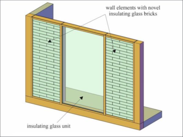
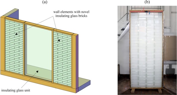
A novel type of insulating aerogel-filled glass brick was recently developed to be used for exterior walls (Ganobjak et al. 2023). Due to the aerogel filling it is translucent and reportedly reaches a thermal conductivity of 53 mW/(m·K) and a heat transfer coefficient of around 0.365 W/(m2·K). Due to its insulating, non-transparent but translucent properties, it is considered suitable for applications with increased demand for daylight and at the same time requirements for glare protection and privacy. Its envisioned application is not to replace transparent window or façade glazing elements, but to provide an alternative for the surrounding wall area that allows an increased daylight transmittance (see schematic illustration in Fig. 1a). A mock-up element was manufactured to illustrate the use case as wall element in a facade (see Fig. 1b). The performance of walls built with the novel type of insulating glass bricks, however, has not been investigated yet from a structural point of view. This paper presents first results in this regard based on finite element simulations. The focus is set on out-of-plane loads resulting from wind.
2 Systems and materials
2.1 Description of the translucent and insulating glass brick
Two brick geometries were assumed for the simulation of walls with the novel type of insulating glass bricks—a full-brick and a half-brick. An image of a half-brick assembled on top of a full-brick is shown in Fig. 2a, while the components of the two bricks are illustrated in Fig. 2b. The full-brick had dimensions of length × width × height of 500 mm × 150 mm × 85 mm, while the half-brick had a different length of only 247.5 mm. Each brick consisted of two laminated glass layers separated by spacer elements. The laminated glass layers were made of 2 × 12 mm annealed float glass. Annealed glass was preferred to thermally tempered glass since it allows for mechanical processing. Hereby, larger panels can be first laminated and afterwards cut into size and edge-processed. For the PVB interlayers, a thickness of 1.52 mm was assumed in the simulations.
PVB was chosen since there was no need for the higher stiffness provided by SentryGlas interlayers. General details on the properties of the materials used for the laminated glass can be found in Haldimann et al. (2008) and Schneider et al. (2016). The spacers with a resulting width of 99 mm were made of a two-component epoxy resin (Esprit Composite Epoxid-Kristallharz EC 141). The dimensions provided in this section for the brick components are according to those used for the assumptions in the performed simulations. For the above-mentioned physical prototype shown in Fig. 2a, slightly different dimensions were used (e.g., the resulting width of the spacers was 102 mm instead of the 99 mm used in the simulations). The epoxy resin was previously used for casting transparent objects, like jewellery, and had no previous applications in facades. It was chosen for the brick prototypes mainly based on its high clarity and low viscosity.
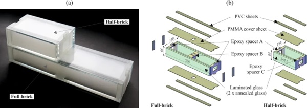
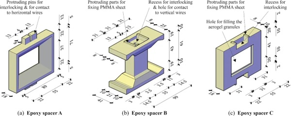
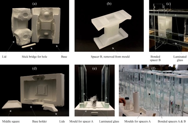
The geometries of the different spacers are illustrated in Fig. 3. The complex geometries of the spacers resulted from optimizations regarding assembly of the bricks and thermal performance. Three different spacer geometries were used—(1) spacer A at the ends of the full-brick and at the interior end of the half-brick, (2) spacer B in the middle of the full-brick, and (3) spacer C at the exterior end of the half-brick. The spacers B were cast separately in silicone rubber moulds and were bonded afterwards to the laminated glass layers (see Fig. 4a–c). The spacers at the ends of the bricks (spacers A and C) were cast directly between the laminated glass layers, which were positioned in a silicone rubber mould on their shorter edges (see Fig. 4d–f). First, the spacer at one end of the bricks was cast and let to cure, and then the bricks were flipped by 180° and the spacer at the opposite end was cast. To cover the space defined by the laminated glass and the spacers, 1.5 mm thick plates made of PMMA were used.
Moreover, a 0.5 mm thick layer made of the same epoxy resin as used for the spacers was cast on the interior face of each of the PMMA plates to ensure tightness between the spacers, the glass and the PMMA. For these thin layers, the epoxy resin was poured through the openings of the end spacers (spacers A and C), first on the interior surface of one of the PMMA cover sheets, and then on the other, after curing and turning the bricks upside-down. The interior space of the bricks was then filled with tapped aerogel granules (Lumira LA1000 from Cabot). This material has a visible light transmittance of over 90% per cm and a thermal conductivity of around 18–23 mW/(m·K) according to Cabot (2000). The openings, through which the aerogel was filled, were finally sealed with transparent tape. A wall section made of such aerogel-filled bricks including the spacers and the gaps between bricks reaches a U-value of approximately 0.4 W/(m2·K), which is lower than the U-value of a state-of-the-art triple IGU with down to 0.5 W/(m2·K).
For a previous version of the full-brick, with the same length of 500 mm and consisting as well of four 12 mm thick annealed float glass layers, the compressive strength was investigated experimentally (Ganobjak et al. 2023). The brick was positioned as it would be used in a brick wall and the force was applied through plywood layers to avoid local stress peaks. A force of 3042 kN was recorded before failure, corresponding to a compressive stress of 126.75 N/mm2 in the glass for the given glass area. Considering the weight of one full brick of approximately 5.8 kg, bearing the self-weight can be regarded as non-problematic for walls made of such bricks and reasonable storey heights.
2.2 Assembly and support systems for the translucent walls
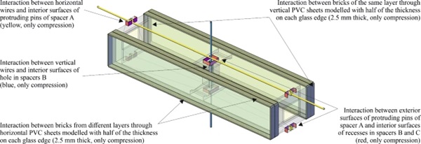
Two systems for supporting walls made from the novel type of insulating glass bricks were considered for the investigations discussed in this paper. The first support system was based on a mesh of horizontal and vertical pre-stressed stainless steel wires with a diameter of 3 mm. The horizontal wires were positioned between different layers of bricks and absorbed occurring horizontal out-of-plane loads acting on the walls (e.g., wind), through contact with the protruding pins of the spacers A in both full-bricks and half-bricks. The vertical wires were positioned between adjacent bricks of the same layer and through the holes in spacers B of bricks from layers above and below. They absorbed horizontal out-of-plane loads acting on the walls through contact with the spacers B in the full-bricks. For the second support system, an alternative without wires was considered. Edge clamping of wall elements on two or four sides, as it is used for glazing units or façade panels, was assumed. Between the clamping strips, gaskets made of EPDM or silicone were assumed. Sketches of the two support systems with their components are shown in Fig. 5. The system with wires would provide the advantage of potentially allowing for less wide posts, while the system with clamping would allow a further simplification of the spacer geometries.
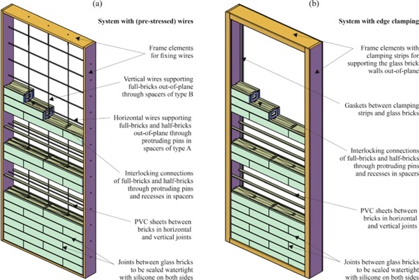
For both systems, the bricks were planned to be assembled in a dry manner by placing 5 mm thick and 25 mm wide PVC sheets both in the horizontal and in the vertical joints for avoiding direct glass-to-glass contact. In two consecutive layers in vertical direction, full-bricks laid on top of each other showed an offset by half of their length. The force transfer between adjacent bricks from different layers was realized for both systems through interlocking connections ensured by the spacer geometries with protruding pins and recessing parts. For a façade application, the joints between bricks would be sealed with silicone sealant (or grout) near the exterior and the interior surfaces of the walls, to ensure weather tightness. This would require a small offset of the PVC layers towards the interior of the bricks.
When building with glass, a damage of components made of this material needs to be considered. A replacement of damaged single bricks in the two introduced assembly and support systems is not easy, but possible. Having the bricks assembled in framed elements (both for the system with wires and for that with edge clamping), a replacement of a single brick could be done by removing one such framed element, and then removing all dry-stacked glass brick layers down to the damaged one. Since also the silicone sealant necessary for weather tightness between bricks would need to be removed for disassembling and replaced afterwards, and depending on the position of the damaged brick, the replacement process might require substantial labour.
3 Methods
3.1 Uniaxial tensile and compressive tests on epoxy resin used for spacers
There are no previous structural applications of the epoxy resin used for the spacers in the bricks. Therefore, uniaxial tensile and compressive tests were conducted to determine its mechanical properties under room ambient conditions (around 20 °C and 50% relative humidity).
For the tensile tests, coupon specimens of Type 1A with a thickness of 4 mm were manufactured according to (EN ISO 527-2 2012). The specimen geometry and the test setup are shown in Fig. 6a. The specimens were cast in silicone moulds by mixing the two components in a ratio of 2:1 between resin and catalyst. The test specimens cured under room ambient conditions for seven days before testing. The tests were conducted under displacement control on a Zwick/Roell universal testing machine. Two different displacement rates of 1 mm/min and 10 mm/min were used. Sheets of sandpaper with grit size P100 were bonded on the specimen surfaces in the clamping area to improve the grip. The force was measured with a 10 kN load cell, while for the displacements a digital image correlation (DIC) system was used in addition to the traverse displacement. The front surfaces of the specimens were covered first with a white flat paint and afterwards, a black speckle pattern was applied with an airbrush system.
The DIC strain and displacement measurements were conducted with a VIC-3D 9 system from Correlated Solutions, Inc. with two FLIR 12.3 MP cameras equipped with Rodagon lenses with a focal length of 80 mm. Five specimens were evaluated for each of the two displacement rates. First, three cycles up to a force of 800 N were conducted and afterwards the specimens were tested to failure. The Young’s modulus, the maximum engineering stress and the corresponding engineering strain (ultimate strain) were evaluated for this last cycle. The Young’s modulus was evaluated as linear regression between engineering stresses of 5 MPa and 20 MPa, corresponding approximately to 10% and 40%, respectively, of the failure stress. The stresses were calculated with the measured initial cross-sections, while the strains were determined based on a virtual extensometer applied over a length L0 = 75 mm of the specimen part with constant width.
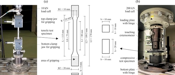
For the compressive tests, prismatic specimens with a height of 20 mm and a square cross-section with an edge length of 10 mm were cast. The chosen geometry was based on the indications in (EN ISO 604 2002). The specimen geometry and the test setup are shown in Fig. 6b. The tests were conducted on the same universal testing machine under displacement control with displacement rates of 1 mm/min and 10 mm/min. The forces were measured with a 200 kN load cell, while the displacements were measured with a touching extensometer between the load application and the support plates until 4 mm compression, corresponding to 20% of the initial height of the specimens. Some of the tests were continued beyond this compression value after removing the extensometer. The Young’s modulus, the maximum engineering stress and the corresponding engineering strain were evaluated for the compressive test specimens. The stresses were determined based on the initial measured cross-sections, while the strains were calculated based on the extensometer measurements. The Young’s modulus was determined as linear regression between engineering stresses of 20 MPa and 40 MPa. Three specimens were evaluated for each of the two displacement rates.
3.2 Finite element simulations on single translucent glass brick
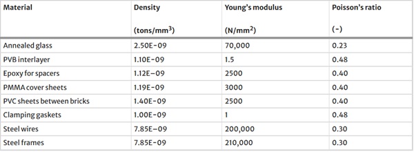
Finite element simulations were conducted in the computer-aided engineering software (Abaqus/CAE 2021) on a single translucent full-brick in order to assess different finite element types and mesh densities. The objective of this study was to reduce the computation time for the simulations at wall-level. The bricks were modelled as one single part with partitions for assigning the different materials. The components of a brick in the model as well as the applied boundary conditions and loading are illustrated in Fig. 7a. One brick included the two laminated glass packages consisting of two glass layers and a PVB interlayer each, a spacer element composed of all the spacers in a brick and the PMMA cover plates, and vertical and horizontal PVC sheets with a thickness of 2.5 mm along all glass edges. The aerogel granulate was not included in the model, since it was not expected to have a significant influence on the structural behaviour of the glass bricks and glass brick walls. In addition, an eventual load transfer between the two laminated glass layers through the cavity was considered to have an insignificant contribution and was neglected. The properties of the different materials as used in the simulations are provided in Table 1. For the epoxy resin, a yield stress of 50 N/mm2 was defined in addition to the elastic properties. The table also includes materials that were only used in the simulations at wall-level (see Sect. 3.3).
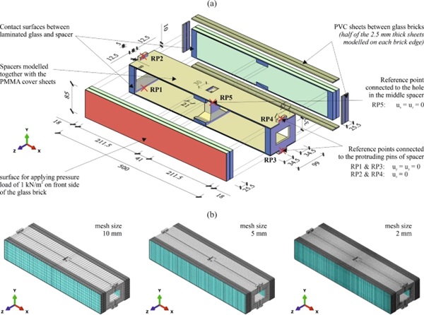
Table 1 Selected properties of the different materials used in the translucent and insulating aerogel-filled glass bricks and brick walls, as assumed in the simulations discussed in this paper - Full size table
Chamfers at the glass edges as well as eventual offsets of the PVC layers towards the interior of the bricks were neglected in the models. The different spacers in one brick and the PMMA cover plates were modelled as one material with the properties of the epoxy resin for two reasons: (1) their mechanical properties do not differ significantly, and (2) due to the thin epoxy resin layer poured on the PMMA cover plates, the spacers and the plates could be assumed as bonded together. Moreover, the spacer geometry was slightly adapted/simplified compared to the real one to ease the meshing and later in the simulations at wall-level the contact definitions. The 2.5 mm thick PVC sheets along the glass edges represent half of the layers used between adjacent bricks. They were modelled directly on the bricks, to allow the definition of a single contact interaction between adjacent bricks in the wall simulations. In the single brick simulations, the boundary conditions were applied on reference points as if vertical and horizontal wires would be used. Therefore, five reference points (RPs) were defined and connected to spacer surfaces: RP1-RP4 on the protruding pins of the spacers A at the extremities of the brick and RP5 for the hole in the spacer B in the middle of the brick. A load simulating a wind pressure of 1 kN/m2 was applied on one exterior glass surface.
All components of the full-brick were modelled with solid elements. The following element types were considered: 8-node linear elements with reduced integration (C3D8R), 8-node linear elements with full integration (C3D8) and 20-node quadratic elements with reduced integration (C3D20R). For each of these element types three different global mesh sizes were evaluated—10 mm, 5 mm and 2 mm—as illustrated in Fig. 7b. For comparing the results obtained with the different element types and mesh sizes, global deformations, maximum principal stresses in the glass layers and Mises stresses in the spacers were evaluated.
3.3 Finite element simulations on translucent glass brick walls
Finite element simulations were conducted on translucent glass brick walls with the two support systems introduced in Sect. 2.2. The full-bricks were modelled as described in Sect. 3.2 with 8-node elements with full integration (C3D8) and a global mesh size of 10 mm. Only in the area of the protruding spacer pins, the mesh was refined to 2 mm for improved contact behaviour. The half-bricks were modelled in a similar way as the full-bricks. Gaps in the interlocking connections between spacers of different bricks, which are resulting from manufacturing tolerances and are necessary for assembling, were neglected in the simulations. These gaps resulting between protruding spacer pins and recessed spacer parts had dimensions of around 0.5 mm to 1.0 mm in case of the realised mock-up.
For the interaction between different bricks, contact properties were defined as follows: (1) hard contact that allows separation in normal direction, and (2) friction with an assumed coefficient of 0.1 in tangential direction. These properties were defined both between the interlocking spacer parts of bricks positioned on top of each other, and between the PVC sheets belonging to adjacent, dry assembled bricks. This type of interaction allowed transferring forces between these parts only by compression, while in case of tension gaps would result. The modelling assumptions in terms of supports for the two considered systems—with pre-stressed wires and with edge clamping, respectively—are illustrated schematically in Fig. 8.
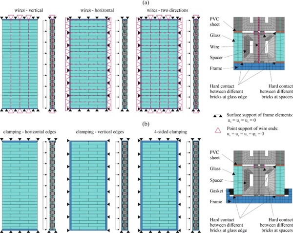
For the support system with wires, the wires were modelled as linear beam elements (B31) with a diameter of 3 mm and a mesh size of 2 mm. Such elements proved to allow a more stable convergence of the simulations compared to truss elements. For the material properties, stainless spring steel wire was assumed according to (EN 10270–3 2011). The wires were supported at both of their ends by fixing all their translational degrees of freedom and the rotation around their own axis. The contact between the wires and the defined spacer surfaces (see sketch in Fig. 9) was modelled with tie constraints to facilitate convergence in the simulations. The pre-stress of the wires was applied through predefined fields by cooling the wires by 47 °C.
This led to a pre-stress of around 150 N/mm2, corresponding to around 10% of the assumed ultimate strength of 1,500 N/mm2 for the wires. The frame elements around the brick wall were modelled as well. However, only for the bottom frame beam contact to the bricks was defined, while in the other directions a gap of 10 mm was left based on the assumption that this would be necessary for eventual thermal elongations. Therefore, these beams are included only as reference for the deformation of the brick wall. The frame parts were supported by fixing all translational degrees of freedom of their exterior surfaces. The assumption of rigid frames is correct when the frames can be connected to existing slabs and columns or walls, but otherwise their real stiffness and resulting deflections would need to be considered.
For the support system with clamping along the edges of the brick wall, gaskets with a width of 18 mm and a thickness of 12 mm were assumed along the edges on both the front and the back of the bricks at the supported wall edges. The gasket material was connected with tie constrains to the frame elements, which were also modelled for these systems. The connection between gaskets and the corresponding glass surfaces were modelled as well with tie constraints to facilitate convergence of the simulations. Between frame elements and glass bricks, contact was only modelled for the bottom frame beam, while for the other frame elements a gap of 10 mm was assumed between them and the brick, similar to the system with pre-stressed wires. All the frame elements were supported at their exterior surfaces by fixing all translational degrees of freedom.
Out-of-plane loading, as it would result due to wind, was modelled as pressure with p = 1.0 kN/m2 on one of the glass brick wall surfaces. The self-weight was neglected in the present investigations for all simulations to reduce the complexity in terms of closing and separating contacts (convergence issues). An addition of the self-weight would further reduce the resulting out-of-plane deformation.
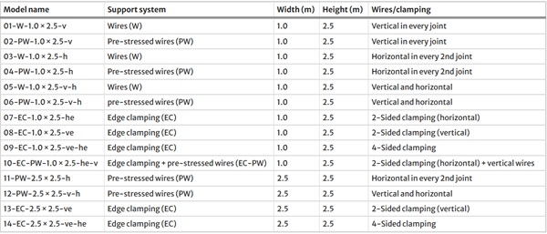
A glass brick wall element size with a width of around 1.0 m and a height of approximately 2.5 m was considered, corresponding to the size of the mock-up element shown in Fig. 1b. For the system with pre-stressed wires, alternatives with only vertical wires, only horizontal wires and both vertical and horizontal wires were considered. Moreover, simulations without pre-stress and such with a pre-stress of 150 N/mm2 were conducted. For the system with edge clamping, clamping only along the horizontal edges, only along the vertical edges, and four-sided clamping were considered. In addition, one system with clamping along the horizontal edges and pre-stressed vertical wires was included. Moreover, a second brick wall size with the same height and a width of around 2.5 m was investigated for the systems with four-sided supports and two-sided support along the vertical edges. A matrix with an overview of the different simulations is given in Table 2.
Table 2 Matrix of investigated models for translucent walls with the novel type of glass bricks - Full size table
4 Results and discussion
4.1 Mechanical properties of epoxy resin used for spacers
In both investigated support systems for the translucent brick walls, dry interlocking connections were used between the different layers of bricks. These connections were realised through the designed spacer geometries. Therefore, the mechanical properties of the selected epoxy resin were of interest. The stress vs. strain relationships obtained from the tests conducted under uniaxial tensile loading and uniaxial compressive loading at room ambient conditions are shown in Fig. 10a and b, respectively, as engineering values. Under tension, the epoxy resin exhibited an almost linear stress vs. strain behaviour before reaching ultimate stress values of approximately 50 N/mm2. With higher displacement rate, slightly higher stress values were reached.
The stress vs. strain behaviour under compressive loading was almost linear before yielding occurred. Yield stress values of around 75 N/mm2 were reached for a displacement rate of 1 mm/min, while with the ten times higher displacement rate, around 30% higher values were obtained. Large plastic strains were noticed under compressive loading after yielding. The curves in Fig. 10b extend only until compressive strains of 20–25%, at which the extensometer was removed. However, for some specimens the tests were continued afterwards. Figure 11 shows one such specimen at different stages of a test carried out until 50% compressive strain. It can be observed that a bulge resulted in all directions before reaching 10% strain. Afterwards, this bulge grew until ultimate failure occurred between 40 and 50% strain due to transverse tensile failure.
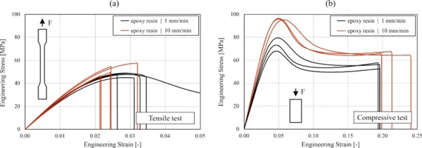

Table 3 provides selected mechanical properties determined from the tests as average values. The displacement rate dependency of the Young’s modulus proved to be small under tensile loading, while varying a little more under compressive loading. For the maximum stress, the ultimate stress was considered under tensile loading, while under compressive loading the yield stress is given in Table 3. Higher stress values were reached under compression after yielding and before failure due to transverse tension, however, the strain values at which these stresses occurred are beyond those interesting for practice. In the case of the interlocking spacers parts used for connecting the glass bricks, the tensile strength in the protruding pins is expected to be the limiting criteria.
Table 3 Selected mechanical properties of the spacer epoxy resin as mean values based on the uniaxial tensile and compressive tests - Full size table
4.2 Finite element mesh study for single glass brick
For the simulations on a single glass brick under a pressure load of 1.0 kN/m2 acting on one of the exterior glass surfaces, the overall displacements (see Fig. 12), the maximum principal stresses in the glass (see Fig. 13) and the Mises stresses in the spacers (see Fig. 14) were evaluated. Despite the very low values resulting for all these outputs, the study allowed to assess suitable finite element types and mesh sizes for the simulations at wall level. Further, the stress plots indicated the location of higher stresses in the glass layers an in the spacers. For the glass, the highest stresses occurred in the inner glass sheet of the loaded laminated glass in the area of the middle spacer B as a hogging effect. For the spacers, the highest stresses occurred in the protruding pins of the spacers A.
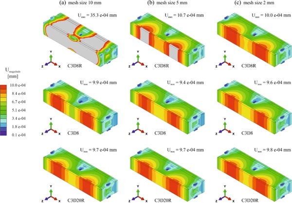
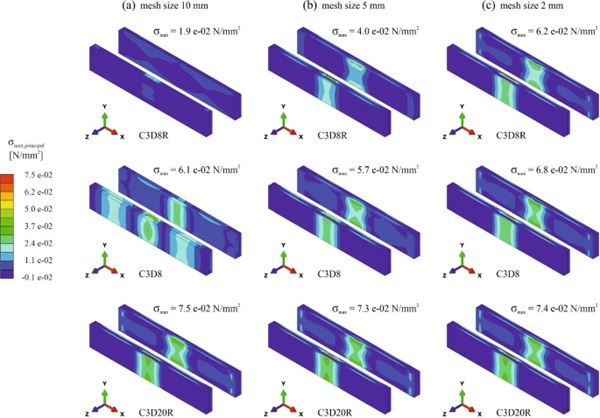
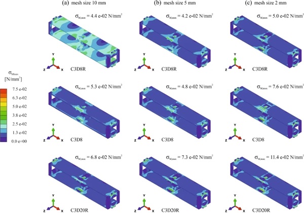
From the Figs. 12, 13 and 14, it can be noticed that by using the coarsest discretisation with 8-node solid elements with reduced integration and a mesh size of 10 mm, the displacements were overestimated, while the stresses were underestimated both in the glass and in the spacers. Even a mesh size of 5 mm did not lead to satisfying results with this type of elements. In case of the finest discretisation with 20-node solid elements with reduced integration, the most accurate results would be assumed. However, for the Mises stresses in the spacers, singularity points led to higher values than for all other models.
For the simulations at wall-level, a mesh size of 10 mm with 8-node solid elements with full integration was chosen. Despite leading to slightly lower stresses in the glass and in the spacers compared to models with the same mesh size and 20-node solid elements with reduced integration, this was considered acceptable for comparing the different brick wall support systems to each other. For the single brick, this compromise led to an approximately four times shorter computation time. The computation time with the finest discretisation was around 1,100 times longer. Moreover, a mesh refinement to a size of 2 mm was used in the areas of the protruding spacer pins for more accurate results in these zones.
4.3 Structural behaviour of translucent glass brick walls
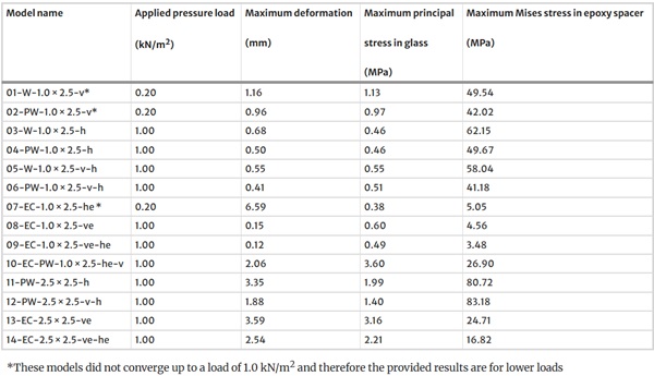
This section presents and discusses the results obtained from simulations of translucent glass brick walls with the different support systems described in Sects. 2.2 and 3.3. Table 4 provides an overview of global deformations, maximum principal stresses in the glass and maximum Mises stresses in the epoxy resin spacers resulting under an out-of-plane load of 1.0 kN/m2. For some of the models, as specified in the table, the whole load could not be applied due to convergence issues.
Table 4 Selected results from the performed simulations on translucent walls with the novel type of glass bricks loaded by a surface load of 1.0 kN/m2 - Full size table
For better qualitative and quantitative visualisation of the deformation behaviour of the glass brick walls with the different support systems, deformation plots are provided for the 1.0 m wide elements in Fig. 15 and for the 2.5 m wide elements in Fig. 16. The deformations were plotted with a scaling factor of 100. In case of the 1.0 m wide elements with wires, deformation contour plots are shown in Fig. 15a only for the alternatives with pre-stress. From the results in Table 4 and the plots in Fig. 15, it can be observed that the occurring maximum deformations are rather small for all the investigated systems, not exceeding 1/300 of the span.
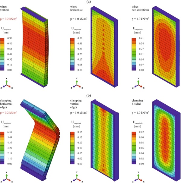
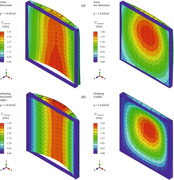
The highest displacements resulted for the systems spanning over the height of the glass brick walls, namely those with only vertical wires (models 01 and 02) and that with edge clamping along the horizontal edges (model 07). These were also the systems for which results were only obtained for a pressure of 0.2 kN/m2. In both cases, the convergence issues were due to difficulties in finding equilibrium under the occurring displacements with the given complex contact interactions. The deformation plots are not symmetrical in height direction because of the contact defined between bricks and frame only at the bottom. At the top, the movement of the bricks was not limited because of the assumed gap of 10 mm. In case of the system with vertical (pre-stressed) wires, most of the displacement was a rigid body movement of the glass bricks relative to the frame. For the system with edge clamping along the horizontal edges, the displacements resulted due to gaps opening gradually between the different brick layers on the opposite side to the loaded one. Only the lever resulting through the compressed glass brick edges and the pressure/friction in the interlocking spacers resisted the bending deformation. A combination of these two supporting systems (model 10) was investigated as well and showed significantly better results: the edge clamping impeded the rigid body displacement, while the vertical wires were more efficient for resisting the bending together with the compressed glass brick edges compared to the interlocking connections alone.
The 1.0 m wide systems spanning over the width of the glass brick walls, namely those with only horizontal wires (models 03 and 04) and the one with edge clamping along the vertical edges (model 08) behaved significantly stiffer according to the obtained maximum deformations. This was on the one hand due to the shorter span and on the other hand due to the lower number of possible gap openings between bricks. Moreover, the offset by half of a brick between layers contributed to the increased stiffness. The systems spanning in two directions with vertical and horizontal wires (model 05 and model 06) and the one with four-sided edge clamping (model 09) led to a further decrease of the resulting deformations, as expected. The effect of the pre-stress applied on the wires on the deformations of the walls is shown by the results in Table 4. A deformation reduction of around 25% could be achieved for these systems with the pre-stress level of 150 N/mm2.
For the 1.0 m wide elements, both for the systems spanning over the width of the walls and for those spanning in two directions, the edge clamping resulted in slightly more than three times lower deformations compared to the pre-stressed wires. However, one should consider that most of the deformation for the systems with wires occurred as a relative rigid body movement of the glass bricks relative to the frame. Interestingly, for the 2.5 m wide wall elements, the systems with edge clamping exhibited slightly higher deformations compared to those with pre-stressed wires.
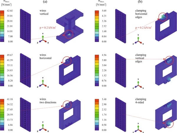
In addition to the deformations, the occurring stresses in the glass layers and in the spacers were evaluated. Besides the values provided in Table 4, stress contour plots obtained from the simulations on 1.0 m wide elements are provided for the glass layers in Fig. 17 and for the spacers in Fig. 18. The location of the bricks exhibiting maximum stresses is pointed out, along with the location of the maximum stresses in the respective bricks.
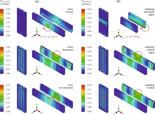
The maximum principal stresses in the glass layers reached quite low values. For the 1.0 m wide elements, the maximum values were reached for the systems spanning over the glass height, despite the models 01 and 02 only converged up to a load of 0.2 kN/m2. The system with vertical wires and edge clamping along the horizontal edges (see model 10 in Table 4) reached the highest values with 3.60 N/mm2, which is still significantly lower than the tensile bending strength of annealed float glass. For the investigated 2.5 m wide elements, the size of the maximum principal stresses in the glass increased slightly compared to the corresponding 1.0 m wide elements. However, the values were still significantly lower than the strength of the glass. The location of the maximum stresses were in most cases in the inner glass layer of the laminated glass on the side facing away from the load. The position of the brick exhibiting the maximum values in the wall elements depended on the support system and was located rather at the bottom or at the top of the wall for systems spanning in one direction and more towards the middle of the wall for systems spanning in two directions.
For the spacers, the Mises stresses were evaluated. The resulting values were significantly higher for the systems with wires (see Fig. 18a) compared to those with edge clamping (see Fig. 18b). The position of the bricks exhibiting the maximum values corresponded well to the bricks exhibiting the highest glass stresses. The locations of the maximum Mises stresses were very isolated. For the system with wires, this corresponded to the contact points in which the wires touched the spacers. For the system with only vertical wires the maximum Mises stresses were in the inner hole of a spacer B, while for the systems with only horizontal wires and that with wires in two directions, the maximum Mises stresses occurred in the recesses of the protruding pins of spacers A. For the 1.0 m wide elements, the maximum stresses in the spacers were reduced by pre-stressing the wires (see Table 4). The size of the maximum stress values for the systems with wires exceeded in some cases the tensile strength of 47.6 N/mm2 and in case of the model 11, even the compressive yield strength of 73.5 N/mm2 determined for the epoxy resin with a displacement rate of 1 mm/min in the conducted tests. For the systems with edge clamping, the maximum Mises stresses in the spacers occurred in the protruding parts of the spacers ensuring the interlocking connections. Their size was significantly lower compared to the systems with wires. For the 1.0 m wide elements the difference was approximately by a factor of ten; however, this difference was lower for the wider wall elements.
Based on the findings from the conducted simulations, it can be overall concluded that systems spanning over the width of the wall elements and systems spanning in two directions behaved well in terms of deformations. Systems spanning over the height of the elements, either only with wires or only with edge clamping along the horizontal edges, showed higher deformations and convergence issues in the simulations. A system with combined edge clamping along the horizontal edges and vertical wires, however, might be a suitable solution in case it is aimed not to use vertical mullions. One should also consider that the conducted investigations did not consider the self-weight of the glass bricks, which would have a positive effect on reducing the occurring deformations under out-of-plane loading. As mentioned previously, some of the simulations exhibited convergence issues. Considering the complex contact interactions between the glass bricks, the use of the explicit solver might be more suitable for such simulations than the implicit solver used for the investigations in the current paper. However, a proper validation of assumptions necessary for using the explicit solver for quasi-static problems (e.g., time scaling and mass scaling) is only considered feasible through experimental results. Such were not available for the investigated situations or similar ones.
In terms of resulting stresses, the simulations showed that glass failure is rather unlikely to occur due to out-of-plane loading for the investigated configurations. The weakest elements in the glass bricks proved to be the epoxy resin spacers, especially the parts ensuring the force transfer to the wires and the protruding pins ensuring the interlocking connections. Considering that higher loads than the pressure of 1.0 kN/m2 assumed in these investigations might occur and that the properties of the epoxy resin used for the spacers would very probably degrade with higher service temperature, experimental investigations on the structural behaviour of the spacers and optimizations of its geometry are necessary.
5 Outlook on optimization possibilities for the translucent brick walls
The conducted finite element simulations showed the suitability and relatively good structural performance of some of the investigated support systems for translucent walls made from the novel aerogel-filled glass bricks. At the same time, the findings indicated existing optimization possibilities of which some are highlighted in this section.
The annealed float glass sheets used in the current version of the bricks are 12 mm thick. Since only low stress values were observed in the simulations, eventually the glass thickness might be reduced, especially if the walls are only self-bearing and not intended to carry loads from the main structure (e.g., slabs). A reduced thickness of the glass would actually improve the thermal performance of the bricks and is expected to only lead to a very limited increase of out-of-plane deformations. Moreover, the aerogel-filled glass bricks are translucent, not transparent. Therefore, also the optical quality requirements for the glass are not extremely high. Annealed glass from end-of-life window or façade glazing could be considered for remanufacturing into such glass bricks, even if it exhibits surface scratches.
The current size of the bricks was chosen to reproduce the appearance of conventional brickwork. Larger (higher) single bricks are however worth considering. This would reduce the number of brick layers and gaps between them for the same wall height, hereby also reducing the length of thermal bridges. However, this would eventually also lead to increased stressing of the interlocking spacer parts. Regarding the spacer, various optimizations are possible from a structural point of view. Depending on the chosen support system, the geometry of the spacers could be optimized to more efficiently transfer the loads. More important, the epoxy resin currently used needs detailed investigations regarding behaviour at high service temperatures and its durability under the expected environmental conditions. Eventually alternative materials or material combinations inspired from available spacer systems for insulating glass units might prove to be solutions that are more suitable. Moreover, the behaviour of the single brick as well as of the brick walls needs to be investigated under temperature changes in a future step. At single brick level, temperature changes might lead to different thermal elongations of the glass layers and the epoxy resin spacer and, as a consequence, to either delamination between these materials or shear cracks in the glass. Depending on the air tightness of the aerogel-filled cavities, temperature changes might also lead to pressure changes in these cavities and, as a consequence, to stresses in the sealing tapes. At brick wall level, temperature changes will lead to an increase or decrease of the pre-stress in the wires for the respective systems. Future investigations of the single brick under temperature changes might also lead to necessary adaptations and optimizations of the spacers.
6 Conclusions
The results discussed in this paper allowed assessing the structural performance of different support systems for walls made of translucent aerogel-filled glass bricks loaded by out-of-plane loads. The findings led to the following conclusions relevant for further development of such systems:
- The epoxy resin used for the spacers in the aerogel-filled glass bricks had a similar stiffness under tensile and under compressive loading at room ambient conditions. However, while it showed a brittle failure in the uniaxial tensile tests, it behaved ductile in the compressive ones.
- The finite element studies on a single glass brick showed that with linear solid elements with reduced integration a very fine mesh was necessary for reasonable results, while with linear solid elements with full integration, such results were obtained also with a significantly coarser mesh.
- Walls made of translucent aerogel-filled glass bricks and spanning over the wall height showed a reasonable deformation behaviour when edge clamping along the horizontal edges combined with vertical wires were used as support system. The deformations were significantly higher and the simulations showed convergence issues when only one of the two support systems was used.
- Walls made of translucent aerogel-filled glass bricks and spanning over the wall width or spanning in two directions showed a reasonable deformation behaviour both for support systems with wires and for support systems with edge clamping under the applied pressure load of 1.0 kN/m2.
- For all investigated support systems, only low maximum principal stress values below 4 N/mm2 resulted in the annealed float glass layers. The spacer elements exhibited high local stresses, which for some support systems with wires exceeded the strength determined in the experiments for the assumed epoxy resin.
Careful attention was given to the assumptions made for the performed simulations. Nevertheless, physical experiments at wall assembly level would be useful in a future step for further validating the simulation findings, as well as for assessing the influence of manufacturing tolerances.

