First presented at GPD 2019
Today, I will take you through an overview of the three available techniques for WS de-airing. The objective will be to provide complete and factual information needed for a selection process. Indeed, when it comes to de-airing, you can say that there is more than one way to skin a cat. Each technology has their own advantages and disadvantages. Their own strengths and weaknesses.
The important point is to understand them well, and compare them correctly. In other words, to include all the relevant factors in the mix, and to avoid comparing apples and oranges when a selection needs to be made. Ultimately, I will try to provide you a basic tool that will objectively assist in the decision making when planning the investment of deairing lines.
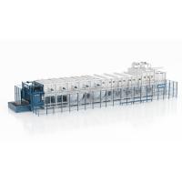
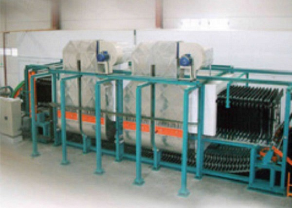
A typical vacuum ring oven line is composed of 3 main sections:
- The entry conveyors,
- The exit conveyors, and
- The actual oven in between which is running from right to left in this example.
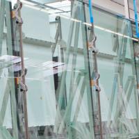
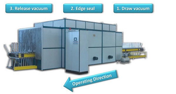
The process starts by fitting the vacuum rings on the periphery of the WS. These vacuum rings are available in (cheap) silicone and (expensive) EPDM material. The latter have the advantage that they do not leave marks on the WS that otherwise need to be cleaned out. However, both have a limited lifetime and need to be replaced relatively frequently. When the WS are placed on the conveyor and the vacuum line is connected, vacuum is drawn to pull out the air between the glass panes before the WS is heated.
The objective is to seal the edges after the air is removed. It is critical that the edge seal is properly formed before the vacuum is released and that no air is allowed to go back in between the glass panes. Here, the process parameters are very important. As you can see in this ideal process chart, the vacuum is drawn whilst the glass is still cool. In this manner, during this step, the surface structure of the PVB remains intact and optimum de-airing can take place.
When de-airing has been done to the required amount, the WS is heated in the oven to approximately 110 to 120º C. This softens the PVB and starts the lamination process. This is the time where the critical edge sealing takes place. The vacuum can be released as soon as the WS temperature drops below a certain threshold. Release it too soon and air can penetrate between the glass panes, as the PVB will not have had enough time to harden and the edge seal would not have been formed.
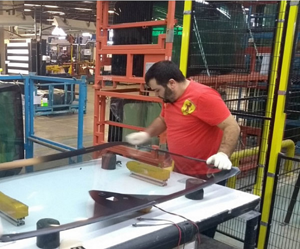
In this video, we are probably seeing the impact of poorly selected process parameters: the exit conveyor is hardly long enough to allow the glass and PVB to cool down. The vacuum is probably released while the WS are still at a temperature where the PVB is still soft, and the edge seal has not been formed. How can we tell?... look at the operators placing these clips! This is a typical operation carried out to avoid or remove bubbles during the autoclave process. Correct process parameters could possibly have avoided or at least reduced this additional operation.
To summarize what we have said:
- Correct selection and optimal process parameters of the PVB are critical for first time yield
- Entry and exit conveyors should be long enough to allow enough time for vacuum drawing and cooling down of the WS
- The rings will not fit all WS shapes and there will be a different set of rings for nearly each WS model. These ring sets have to be switched over during each model change
- Vacuum rings, either Silicone or EPDM need to be replaced every 1000 to 1500 cycles
Let’s talk about vacuum ring lines’ strengths: They are scalable. When you have low volume requirements, you can install a short tunnel. This will save you space, and some costs compared to a full size line.
One of the most important advantages of this technology is that it is very simple and therefore the initial investment of the line is quite low.
Finally, they are very flexible with respect to what you can produce. You should be able to use these lines with simple shapes. You will be able to de-air WSs, SLs, SRs with or without connectors, with or without deep bends in a vacuum ring oven.
There is one caveat with respect to WSs with connectors: it might be necessary to place clips over the rings to ensure that the connectors do not affect the vacuum. On the other hand there are quite a few weaknesses:
- These lines are in general manually operated with few automation opportunities. Automation is mostly possible at the unloading side. Automation becomes unreliable if clips need to be placed over the rings.
- The cycle time is relatively high. Anywhere from 25 to 60 secs.
- They are labor intensive
- The power consumption is high. They are usually powered with electricity and the heating is from convection heating elements. It might not be possible to fit rings around complex shapes and connectors might need additional clamping operations. What is considered a complex shape?... basically any shape that has concave edges, and possibly asymmetric WS’s. Depending on the build of the conveyors, you may also have max-min limitations.
- A separate set of rings is needed for each shape. The longer the oven the higher the amount, and therefore the investment in rings
- Whenever you have a changeover from one shape to another, you will need to switch the whole set of ring which means additional downtime, and either additional labor or investment in some kind of automated storage devices.
- Operational costs are a weakness of this technology. You have relatively high energy consumption, high cost of consumables due to the replacement of the rings, and finally, quite a high cost of maintenance even though the initial out of pocket investment was very attractive.
- And finally, based on the size of the oven, there will be a more or less big impact during stoppages as the line will probably need to be emptied to avoid various types of damages to the WSs in the oven.
Let’s now have a look at the next technology which is the nipper roller line.
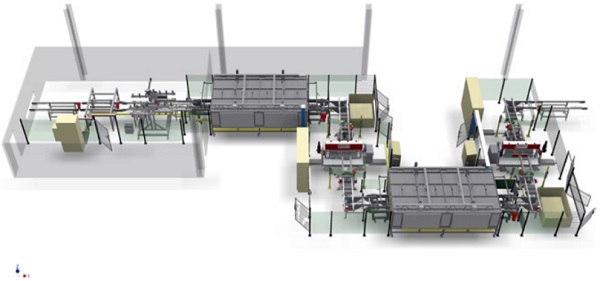
These lines are laid out in a typical U-shape configuration to enable change of orientation from leading long edge to short edge of the WS between the ovens and the nippers. The WSs travel through the line with their wings up. This is not usual when it comes to WS transfer, but you will understand the reason when you see the working principle of the nippers. Here you see a WS in wings up transfer mode in one of the 2 infrared ovens. In the ovens, the WSs travel long edge leading to ensure even heating throughout the entire surface.
Radiation is used rather than convection and conduction. The specific wavelength of these long life lamps directly heats the PVB rather than the glass. Because the PVB does not need to be heated to the same temperatures as in the vacuum ring oven, the PVB does not undergo the physical transformation and remains milky. This is not a defect, but a differentiation of the processes. This also allows for lower energy consumption.
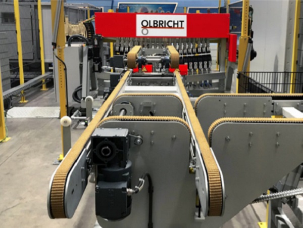
Each oven is followed by a nipper. Nippers are basically working as rolling pins that mechanically squeeze the air out from between the WS. To avoid introducing bubble defects on the windshield it is recommended to work without mechanical referencing on the line. Mechanical stops will bump the edge of the PVB and introduce defects that will result in bubbles and lower the first time yield. This particular model does away with mechanical referencing on the line. Special features are added to the equipment to ensure that the WS travel is controlled throughout the process. There are a total of 10 degrees of freedom that are fully automated on each nipper and its entry and exit conveyors. On the nippers we have
- Automatic smile adjustment to handle the various radii without breakage
- Tilt that moves the nipper forwards and backwards
- Side shift and a
- Rotation to handle the rotation of the WS as it travels through the rollers
These features that are combined to the rotation, tilt and distance adjustments of the entry and exit conveyors ensure that the optimal de-airing is achieved. (Figure 3)
The nipper process is a 2 stage process. The first stage is the de-airing process where the WS glass leaves the first oven at approximately 70ºC and the PVB is softened but the surface structure remains intact. Most of the air is pushed out by the first nipper. The second step is the tacking process. the WS leaves the 2nd oven at approximately 90 to 100ºC, and the PVB is completely softened so that it fully attaches to the glass. The remaining air is pushed out at the 2nd nipper and edge sealing is achieved at this stage. At this point in time the WS is ready to be sent to the autoclave.
One of the major strengths of the nipper technology is its very short cycle time. The cycle time starts at 13 or 14 seconds for simple shapes, and will slightly increase with larger or more complex WSs.
Secondly, it is a process that is fully automated. It can run without the need for any operators. A single supervisor can run the entire line. From the point of view of operational costs, it is very frugal: both energy consumption and maintenance costs are very low. The line has high first time yield.
Start up after line stoppages are very quick in spite of lowered power usage to reduce overall power consumption. On the fly changeover with automated line adjustments.
Line stoppages have practically no negative impact. WS that were in the ovens can be buffered on the conveyors. When compared to large ovens that contain 150 or up to 300 WS that need to be emptied or else they are scrapped, this is a notable difference. Very robust technology with long life expectancy. We have some lines that have been running close to 30 years. Never less than 20 years.
Along with all these strong points, there are also a few weaknesses: First of all, the initial investment is relatively high. Not as high as the vacuum bag line, but higher than a vacuum ring line. However, it is true that when you factor in for capacity and you include all the ancillary equipment that needs to be purchased together with the vacuum ring line, the price difference is no longer so large.
The main drawback of nipper lines, however, is that it can only handle WS without connectors due to the mechanical pressing. As more and more premium car WS have special features that need electrical connectors, this is probably the most important weakness of the nipper roller lines.
In addition to these, there are a couple of minor inconveniences: the footprint is wider than other de-airing lines, even though the total length will generally be shorter.
And there is one operational disadvantage in that the operators cannot rely on visual PPI’s to judge the quality of the process. This is more of an issue for first time users of nipper lines as they will need some time to develop their own process indicators.
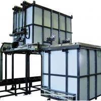
Now we’ll have a look at the 3rd and last technology: the vacuum bag line. The working principle is very similar to the vacuum ring technology. You have the same three sections:
• The entry conveyor
• The oven, and
• The exit conveyors
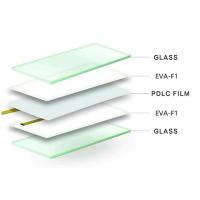
Similar temperature and vacuum parameters are used as in ring technology. The major two differences when compared to the vacuum ring is that you have a set of vacuum bags fixed to the conveyors where the WSs are placed. These bags are not changed for different shapes and any one or more glass can be placed in the bags for de-airing.
The second major difference is that is possible to automate the complete system. In fact, the system is more often than not, run in a fully automated mode.
For instance, here we see a shuttle dropping the WS (it could be a SL or a SR) into the bag. At the unloading side, there is a robot in this photograph that unloads the WS that is ready for the autoclave process.
The most important strength of the vacuum bag, aside the fact that it can be run fully automatically is that it can handle all types of automotive glass without exception. Fast cycle times can also be achieved; although this increases substantially the initial investment.
This technology has the highest first time yield. When first time yield is ranked from worst to best, you get vacuum rings, nipper rollers, then bags.
Finally vacuum bags, like nipper rollers have a quick change over between shapes as long as the recipes have been created. Of course, if the oven parameters need to be modified, you will need to wait for the heat up or cool down period.
Unfortunately, there are some important weaknesses to this technology. First and foremost, the initial investment is very high. If it wasn’t, none of the other technologies would stand a chance, really. Of course, this is assuming that you can afford the also very high energy and maintenance costs. Generally, vacuum bag lines have a high operational cost which can only be covered by value added, high priced premium products. There are two additional inconveniences:
- The footprint required is the largest of all 3 technologies, and
- There is a big impact whenever stoppages occur, as the number of WS in the oven is usually very high, higher in fast cycle lines.
Now that we’ve looked at all 3 technologies, how should one go about selecting the optimal equipment? How should investment decisions be taken? What are the traps that you need to avoid?
There are some obvious and well know parameters that all companies will use to try to make a meaningful cost comparison. These are things like cycle time, or the capacity of the equipment. There is also the expected lifetime of the equipment. However there are many costs that can remain unnoticed, but are as important to avoid cost calculation traps.
You probably already get the idea that this is not an investment that can be decided only based on the price of the equipment. Definitely not a purchase where the buyer goes and selects the cheapest offer! Even if you only looked at the purchase price, there are side costs that add up due to ancillary requirements:
Will you need to buy or build additional infrastructure to supply the increased power requirements? Keep in mind that vacuum rings and bags require a lot of power.
Do you have sufficient storage space for the vacuum rings? What about space for unloading the WS in the line during stoppages? Is there any additional automation that has to be purchased to ensure the line works according to your expectations?
Have you considered the differences in labor between the different systems? This may not be as obvious as counting the operators and supervisors needed on the line. There are hidden labor costs such as rework due to low first time yield, cleaning smudges left by silicone rings, or additional labor when you need to empty the ovens.
I recently witnessed a case at a company where we were installing a WS sub-part assembly line. This company decided to use the lower cost silicone rings. Good for them, as they thought they were saving a whole bunch on their investment costs. (Figure 5.)
Unfortunately, what they didn’t realize was that they had to assign two full time operators to clean every single WS before it went to the subpart assembly! All the WS had marks from the cheaper silicone rings. The sub-part assembly line was in a different plant to the vacuum ring line. So if this had not been brought up during the startup of our sub-part assembly line, the additional labor cost might not have been allocated to the de-airing line, and cost comparisons would have been done with the lower cost silicone rings without consideration of the additional labor! A perfect way to throw off the comparisons.
The last factors impacting overall cost will be the other operating expenses such as replacement of rings and bags and the type of material chosen as well as the overall maintenance costs from year to year. Now, I’d like to share some real world info compiled from some companies that were kind enough to contribute their data under condition of anonimization. So, it could be that, if you are a manufacturer of automotive glass, the data from your company is part of this real world info.
The first set of data that we’ll look at will be the Investment values per 1000 WS over the accounting life of the line. Based on the line features, we can see that for the vacuum ring and the nipper lines the value is less than 50 EUR/1000 WS, slightly higher for the nipper line. On the other hand, the vacuum bag line cost is between 150 and 200 EUR! This is a hefty difference, but if you are producing WS with connectors, and you must have automation, it is an investment that you have to make.
To be able to make a meaningful comparison of the labor costs, we took the actual labor hours for operators and supervisors, including labor for re-working the WS when bubbles were formed and we multiplied it by a fixed theoretical hourly cost. In this case it is not surprising that the vacuum ring lines which have the least amount of automation end up having the highest labor cost among all 3 technologies.
Our next analysis is on the maintenance and operating costs. There are some small amounts related to preventive maintenance as well as spare parts change of wear parts in these costs, but The bulk of the cost here comes from the replacement over time of the rings and bags. Actual maintenance and consumables’ cost per 1000 WS is high for both ring and bag lines. Nipper lines’ maintenance cost is nearly negligible.
When it comes to energy consumption, we again see very large differences. As we would have expected, the nipper has the lowest energy cost among all technologies, whereas the bag, with the large mass that it has to heat has the highest cost of all. (Figure 6)
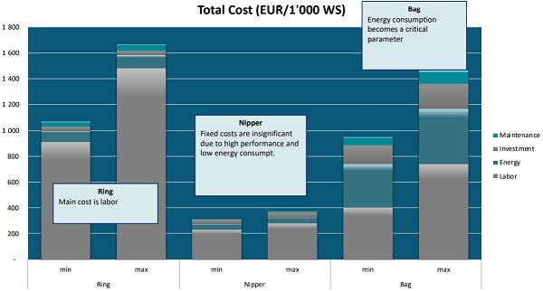
Finally, when you add up all these costs, there are some conclusions that can be drawn straight away:
- Labor is the cost parameter that has the biggest impact overall
- Energy cost’s impact is most marked in the vacuum bag line
- Actual equipment purchase cost is very small for both ring and nipper lines
- Overall best performance belongs to the nipper
- In a European labor cost setting, the vacuum bag line, due to its ability to run with full automation has a better performance than the ring option
But, it is clear that not all investments will happen in Europe and different geographies will have different cost structures. So, how should we select which technology to choose? As always, information and correct analysis is the key. You need to be aware of your current and future product range. You need a strategy regarding automation requirements. Can you live with manual operations? When will you have to start automating your processes? You need to be aware of the relative importance of your cost parameters: labor, consumables, and energy are straight forward. Access to financing might be less so. What are your production targets? Do you have line constraints that require higher or lower cycle times to ensure other, more costly equipment such as press bend furnaces are not underutilized? Ultimately you need to have a good knowledge of all 3 technologies in order to make an informed decision.
This is why we created two interactive tools to assist with the decision process. The first one is a simplified version and relies on some basic questions. We will have a chance to try it in a few minutes. The second tool which you can find on the web site nipperRoller.de allows you to enter your own data and will calculate a cost comparison based on your actual or theoretical parameters such as labor energy cost, yield, maintenance, etc.
Finally, I would like to suggest that a checklist is useful to make sure that all the relevant information is considered: Have you considered all the products that you are producing as well as those that you will produce in the coming years? Do you have a master plan?
Did you consider all the relevant costs, including the hidden ones? Ultimately you will realize that there isn’t a single solution that will fit all your needs and parameters. Rather, you will probably choose a combination of 2 technologies.
When the time comes, I hope you will visit our web site: www.NipperRoller.de where we have both interactive tools to assist you as much as possible.