This paper was first presented at GPD 2023.
Link to the full GPD 2023 conference book: https://www.gpd.fi/GPD2023_proceedings_book/
Authors:
- Laura Galuppi(1)
- Massimo Maffeis(2)
- Gianni Royer-Carfagni(1,2)
(1) Department of Engineering and Architecture, University of Parma, Parma (PR), Italy
(2) Maffeis Engineering SpA, Solagna (VI), Italy
Abstract
The retrofitting of existing buildings, from both the seismic and the energetic point of view, is of paramount importance nowadays. The latter can be achieved through the use of Insulating Glazing Units (IGUs), composed of glass panes held together by structural edge seals, entrapping a gas for thermal and acoustic insulation. Their structural response is governed by the load sharing between the glass elements, due to a complex interaction with the gas in the interspace space. Here, the recently proposed Betti's Analytical Method (BAM) for the calculation of IGUs is reviewed. The model allows to evaluate the response of IGUs composed of an arbitrary number of glass panes of arbitrary thickness, under the most various support conditions and external loads, including line-distributed and concentrated actions. The great advantage compared to other methods is that it provides compact and easy to apply formulas, requiring coefficients that can be summarized in synthetic tables. The BAM approach is here validated by means of comparison with numerical results obtained with MEPLA-ISO software.
Introduction
Insulating Glazing Units (IGUs) consist of glass panes held together by structural edge seals, entrapping a gas for thermal and acoustic insulation. IGUs are widely used as envelopes for energy retrofitting of new and old buildings: together with seismic retrofitting, they are the key way to enhance the safety, energy efficiency and durability in a costeffective way [1].
Changes in temperature and barometric pressure unbalance the external and internal pressures, developing effects in all the panes. When external actions are applied, the bending of one pane induces gas pressure variations, redistributing the loads among the panes and providing a load-sharing effect, depending upon the flexural stiffness of the panes.
While the verification of IGUs under climatic loads is quite straightforward, the methods proposed by Standards [2] [3] to evaluate the load-sharing usually apply only to uniformly distributed loads as external actions. The cases of line distributed and concentrated load require specific tables for each condition, and/ or the use of FEM analyses.
An analytical method based on Betti’s Reciprocal Work Theorem (Betti’s Analytical Method - BAM) has been recently proposed [4]. The method considers IGUs composed by an arbitrary number of glass panes of any shape and arbitrary thickness [5], allowing to evaluate the gas pressure variation under the most general loading conditions. The main advantage with respect to other methods proposed so far is that simple expressions permit to determine the pressure variation once we know one shape function, representing the deformed surface of a simply supported plate, of the same shape of the IGU, under uniform pressure [6] [7]. In practical use, only one table is sufficient to consider many cases in terms of loads and boundary conditions. Once the value of the pressure variation has been determined, it is possible to calculate the stress and deflection in each of the constituent glass panes via tables, or any general-purpose FEM code.
The BAM approach is going to be included in new European Standard [8]. Here, its accuracy is demonstrated by comparisons with numerical analyses, showing the influence on load-sharing of the size and shape of the IGU, glass and spacer thickness, and type of loading condition. The comparison software is MEPLAISO [9], widely used in the design practice.
The BAM approach
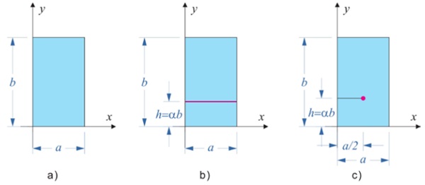
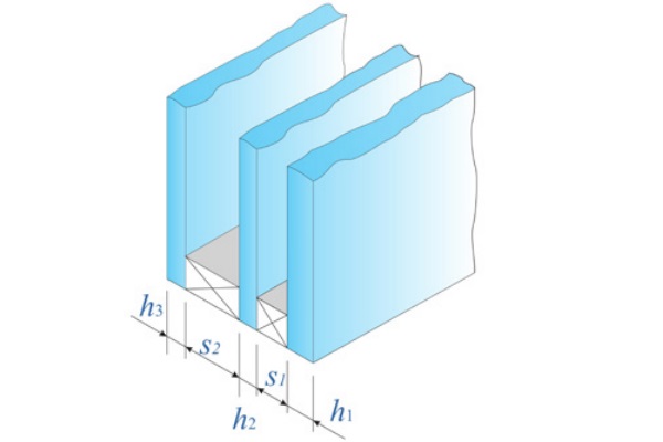
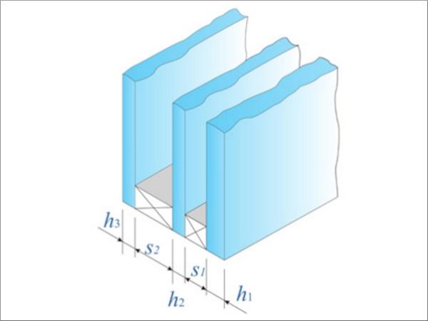
Consider the rectangular IGU shown in Figure 1, with edge length a and b in the (x,y) plane, composed of N=2, 3 glass plies. As indicated in Figure 2, denote by hi , i=1,…,N, and sj , j=1,…,N-1, the thickness of the i-th glass ply and the j-th spacer, respectively.
Define the panel area and the volume of the j-th interpane cavity at the time of sealing as
![]()
When external loads are applied, the reference volume of the j-th cavity may vary, producing a change in the gas pressure Δpⱼ, which sums up with the applied loads and contributes to the panels deformation. The BAM approach [4] [5], based on linear elasticity theory, allows to evaluate Δpⱼ as a function of a non-dimensional shape function φ(x,Y) corresponding to the deflection of a linear elastic plate, shaped as the IGU, simply supported at all edges, under uniform pressure. The relevant (non-dimensional) quantities used in the calculation of IGUs under external loading (either surface distributed, line distributed or concentrated) are the mean value φA of φ(x,Y) over the plate area, its mean value φL on the segment where the line-distributed load is applied, and its value φP at the point of application of the concentrated load. These coefficients, which only depend on the panel shape, can be readily evaluated by using tables and charts recorded in [6].
Define, for the j-th cavity (j=1,…,N-1), the following non-dimensional coefficients:

Double Insulating Glass
For DGUs under load applied on plate "1", the gas pressure variation is evaluated as a function of the coefficient K₁, defined as

which depends on the IGU geometry (size, shape, and thicknesses). When the IGU is subjected to a uniformly distributed load p, the gas pressure variation is given by
![]()
For IGU under a line-distributed load H, acting on a segment of length l, the gas pressure variation is given by

while for the case of concentrated load F it reads.

When the external load is applied on plate 1, the deflection of plate 1 is due to the effects of the applied load -Δp₁, and of a uniformly distributed load (with sign opposite to that of the external load). The other plate (2) will be subjected only to distributed load Δp₁. If the load is applied on both plates, their effect can be superimposed.
Triple Insulating Glass
For TGUs under load applied on plate "1", the gas pressure variation in the two cavities may be expressed as a function of the coefficients

When the IGU is subjected to a uniformly distributed load p, the gas pressure variation is given by
![]()
When the IGU is subjected to line-distributed load H, the pressure variations in the two cavities are given by

while for the case of concentrated load P it reads

In the case where the external load is applied on plate 1, the deflection of plate 1 will be due to the effects of the applied load, and of a uniformly pressure -Δp₁, the intermediate plate 2 is subjected to uniform pressure (Δp₁ - Δp₂), while plate 3 is subjected only to Δp₂. Again, if loads are applied on both the external plates, their effect can be superimposed.
Since the BAM method is based on Betti’s theorem, which is valid within linear elasticity theory, one apparent limitation is that it cannot account for geometric nonlinearities in the response of the glass plates. However, two aspects need to be considered. On the one hand, the pressure variation in the cavity is consequent to the relative deflection of the two confining plates: whereas the absolute deflection of one plate is certainly affected by geometric non linearities, the relative deflection of the two plates is much less influenced. On the other hand, since in general geometric non-linearities increase the plate stiffness, we expect that, under the action of the applied loads, the pressure variation is less than that calculated with eq.s (5-6) and (8-10): to this respect, the BAM approach is on the safe side since it underestimates the coupling of the plates through the gas. The conclusion is that the BAM may be used to evaluate the gas pressure variation, and a FEM analysis, accounting for the geometric non-linearities, will evaluate, a posteriori, the deflection and stress in the glass panes.
Examples and comparisons
The considered IGU geometry is that of a rectangular plate with area A= 4 m², and variable aspect ratio λ=a/b, with loads applied on plate “1”.
Two different geometries are here considered:
- DGU with cavity thickness s₁ = 16 mm, glass thickness h₁ =6 mm and different values of h₂ ;
- a symmetric TGU with s₁ = s₂ = 12 mm, h₁ =h₃ = 10 mm, h₂ = 6 mm
Since the external load is supposed to be applied on pane “1”, the other panes are subjected only to the pressure variations, as discussed in the previous section. The output of MEPLA ISO [9] does not provide the pressure arising in the cavity; hence, the comparison is made in terms of out-of-plane displacement of the not-directly-loaded glass plates. We consider rectangular DGUs because, whereas the BAM approach can be used for DGUs of arbitrary shape, MEPLA ISO can only consider rectangular geometries.
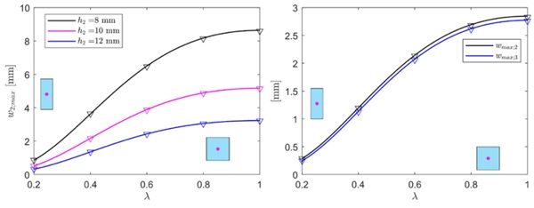
For the case of IGU under uniformly distributed load p = 1 MPa, the pressure arising in the cavities are evaluated by means of eq.s (4) or (8). Figure 3 shows, on the left h. s., the results in terms of maximum deflection of the (unloaded) plate 2, from either the BAM approach (continuous lines) or MEPLA ISO (markers), as a function of the IGU aspect ratio λ in the range [0.2 - 1], for h₂ =8, 10, 12 mm. Obviously, in this case the maximum deflections correspond to square plates ( λ=1). The graph on the right h. s. refers to TGU, and shows the maximum deflections of plates 2 and 3, which are maxima for λ=1. There is an excellent correspondence (maximum error lower than 0.5% for DGU, less than 0.7 % for TGU) between the BAM and the numerical results, for all the considered geometries. As observed in [4], and [5], for this simple case the BAM approach gives results in perfect agreement with the formulation proposed by current Standards, in particular by the European Norm EN 16612 [3]. Consider now the case of a rectangular IGU subjected to a line distributed load H = 1 kN/m, applied at the plate midspan, i.e., at y = b/2 (see Figure 1b, with α =1/2).
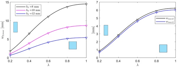
Figure 4 shows the comparison between the maximum deflection of the unloaded panes evaluated via the BAM approach MEPLA ISO, again as a function of the IGU aspect ratio λ. This is considered in the range [0.25 - 4], in order to account for the case of load applied on a line parallel either to the short edge ( λ<1) or to the long edge ( λ>1). There is an excellent agreement between analytical and numerical results, being the mean difference of the order of 0.3% for the DGU, and the maximum difference lower than 0.7% for the TGU.
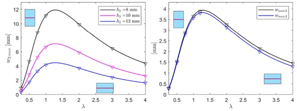
Figure 5 corresponds to the case of concentrated load F= 1 kN applied at the IGU center (see Figure 1c, with α=1/2). The aspect ratio λ is here in the range [0.2-1], due to the symmetry of the considered geometry. In the numerical analyses with MEPLA-ISO, the concentrated force has been modelled as a load distributed on a small 20 mm × 20 mm square imprint. Observe that now the maximum difference is of the order of 0.6% for both DGU and TGU, confirming the accuracy of the proposed model.
The applicability of the BAM for DGUs made of laminated glass elements has been investigated in [6]. In this case, the deflection-effective thickness, i.e., the thickness of a monolith with equivalent bending properties in terms of deflection, shall be considered. The results of [6] confirm the accuracy of the BAM approach.
Conclusions
The recently proposed BAM (Betti’s Analytical Method) approach for the calculation of IGUs, has been revised. The strength of the this approach consists in the fact that it allows to calculate the internal gas pressure without solving the plate problem for each specific external load condition (uniform pressure, line load, concentrated force). The calculation is based on coefficients whose values can be summarized in one table. Compact formulas have been presented to evaluate the pressure variation of the gas in the IGU cavities, for the case of Double and Triple Units. Comparisons with results obtained with MEPLA-ISO software have confirmed that there is an excellent correspondence between analytical and numerical results (maximum error of the order of 0.5%), for DGU and TGU of various size and aspect ratio, under uniform, line distributed and concentrated external actions.
Acknowledgements
The authors acknowledge the support of the Italian Dipartimento della Protezione Civile under project ReLUIS-DPC 2022–2024.
Bibliography
[1] JRC Technical Report “Innovative Materials for Seismic and Energy Retrofitting of the Existing EU Buildings”, 2018.
[2] ASTM E-1300: standard practice for determining load resistance of glass in buildings. Standard, American Society for Testing Materials; 2012.
[3] EN 16612: Glass in building – Determination of the lateral load resistance of glass panes by calculation. Standard, CEN/TC 129; 2019.
[4] Galuppi, L., Royer-Carfagni, G. "Betti’s analytical method for the load sharing in double glazed units." Composite Structures 235 (2020): 111765.
[5] Galuppi, L., Royer-Carfagni, G."Green’s functions for the load sharing in multiple insulating glazing units." International Journal of Solids and Structures 206 (2020): 412-425.
[6] Galuppi, L. "Practical expressions for the design of DGUs. The BAM approach." Engineering Structures 221 (2020): 110993.
[7] Galuppi, L. "Erratum to “Practical expressions for the design of DGUs. The BAM approach”(Engineering Structures 221 (2020)– 110993)." Engineering Structures 232 (2021): 111726.
[8] Feldmann, M., Laurs, M., Belis, J., et al. (2023). The new CEN/TS 19100: Design of glass structures. Glass Structures & Engineering, 1-21.
[9] Bohmann D. MEPLA ISO freeware; 2011. URL:https://www.mepla.net/en/mepla_iso.








Comments
Its main benefit over other approaches is that it offers concise and simple formulas, requiring coefficients that can be condensed into artificial tables.