This paper was first presented at GPD 2023.
Link to the full GPD 2023 conference book: https://www.gpd.fi/GPD2023_proceedings_book/
Authors
- Ingo Stahlkopf - Optris GmbH
- Torsten Czech - Optris GmbH
Abstract
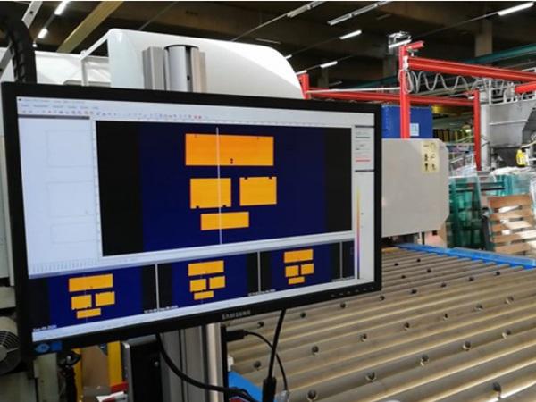
A way to determine the condition and functionality of a glass furnace is to measure the glass temperature as it exits the furnace. Modern furnaces are equipped with infrared devices that captures continuously the infrared information from a designated line (Scan line) taken on the glass as it passes the gap between the furnace and the quenching zone. Out of these scan lines an IR-image is created. The line scan image visualizes the heat distribution inside the furnace. The operator gets feedback of the used settings by identifying areas which may are over or underheated. Condition changes inside the furnace, such as heating losses or heater defects can be monitored easily. Therefore, the IR-image is an important indicator to ensure the quality of glass tempering process. However, since different types of glass with different types of coating have different heat radiation characteristics the IR system must provide the operator with correct temperature information.
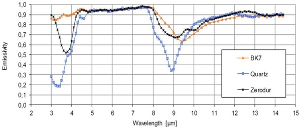
To reduce reflections in general all Infrared devices for such glass measurement applications are operating in wavelengths suited for most glass types. The graphic below gives the emissivity (the part of measured energy that comes from the material) curves for three different types of glass. The range of 5 or 7.9 µm gives the highest emissivity values. That’s why all infrared devices designed for glass applications are operating at one of those spectral ranges.
As soon as the glass is coated the emissivity can be reduced strongly.
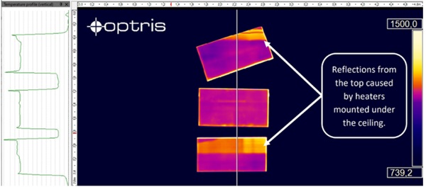
The image below shows a Line scan of a Low-E coated glass with an emissivity of 0.01. That means from all thermal energy radiated from the glass surface the sensor “sees” only 1%. 99 % of what the sensor detects are reflections from the near environment.
In Figure 3 there is an example where heaters were installed under the ceiling above the furnace which are mirrored on top of the glass. Needless to mention that this line scan gives no useful information about the furnace conditions.
Most line scan systems can be equipped with reference sensors. In theory those additional pyrometers measure the glass temperature from the uncoated side underneath. The pyrometer detects the true temperature which means much less reflections and stable conditions. The temperature from the reference sensor is used to correct the IRimage generated from the top. The left image below shows what the IR camera is measuring from the top without referencing. The right image is calculated by the reference sensor temperature. The temperature difference in this case means 442 K in particular.
This kind of systems has its benefits but also its limitations. Each type of coating needs its specific settings. And still, especially for Low-E glass, those kinds of strong reflections are impossible to eliminate completely as to be seen in Figure 3.
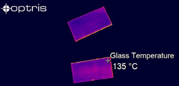
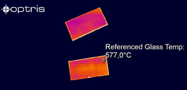
To avoid the reflection issue caused by heaters, windows, lights, or other heat sources the measurement must be done from below the glass completely.
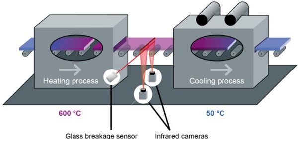
The first challenge for that approach is the limited space between the ground and furnace table. Most existing Line scanners have a fixed focus and need to be installed in a defined distance to cover the whole width. Using two IR-cameras installed underneath the glass provides a new approach. If both cameras are merged the overall image can cover a width of up to 4.2 m by having a distance of 90 cm between ground and glass.
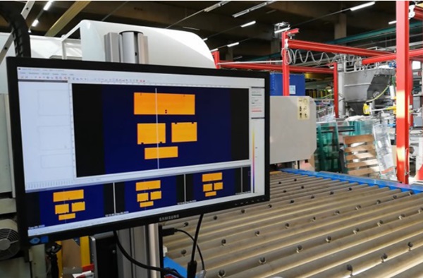
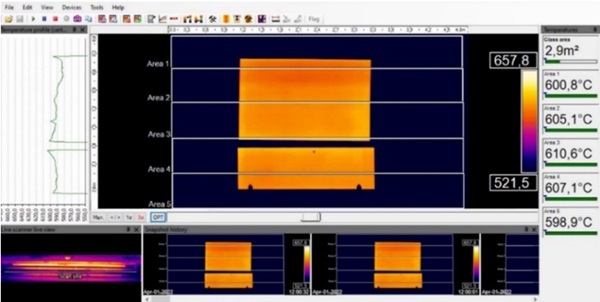
Figure 7 is line scan created by the Optris Bottom Up Glass Inspection System, using 2 units of PI640 cameras. The principle is comprehensible but there are also some facts to consider and challenges to solve. Occasionally the glass breaks by entering the chilling area. In such a case the measurement equipment must be protected from the falling glass. Also during the continuous operation, the equipment needs to be protected so that no dust build up on the lenses, e.g. affect the temperature readings. To counteract these possible issues the Optris system comes with two shutters, one for each camera. They open only when the furnace door is open, and glass comes out. In addition, a highspeed pyrometer is continuously monitoring the area just below the out coming glass. In case of a glass breakage it activates the fast closing mode of the shutters. Due to the short shutter openings the dust contamination is reduced and thanks to the highspeed pyrometer even falling pieces of glass cannot harm the cameras and its optics.




Comments
This meticulous approach ensures that the coated glass maintains its intended characteristics, such as solar control or low-emissivity, while still meeting safety standards. Regular calibration of temperature sensors and adherence to specific tempering guidelines contribute to the overall quality and performance of the coated glass products.