Authors: Efstratios Volakos, Chris Davis, Martien Teich, Peter Lenk & Mauro Overend
Source: Engineering Structures, Volume 274, 2023,
https://doi.org/10.1016/j.engstruct.2022.115164
(https://www.sciencedirect.com/science/article/pii/S0141029622012408)
Highlights
- The impact of temperature on the mechanical response of a liquid-laminated embedded glass connection is assessed via experimental, numerical and analytical methods.
- The stiffness and load-bearing capacity of the connection decreases with increasing temperature.
- The connection failure mechanism is characterised by glass fracture for temperatures at or below ambient indoor temperature while at higher temperatures it is governed by insert delamination.
- A simplified analytical model is introduced that adequately captures the load–displacement response of the connection accounting for the time and temperature dependent behaviour of the interlayer.
Abstract
Embedded load-bearing laminated glass connections have gained popularity in recent years due to their mechanical performance and aesthetic appeal. However, there is a paucity of data on their structural behaviour across a range of temperatures that may arise in building applications and there is also no simplified mechanics-based model for predicting their load–displacement response. This study addresses these gaps directly through experimental pull-out tests on steel inserts encapsulated in resin-laminated glass performed at various temperatures. The experimental results confirm that the response of the resin interlayer is time / temperature-dependent which therefore significantly affects the connection behaviour. In particular, both the stiffness and strength of the connection decrease with increasing temperature.
Similarly, temperature also governs the failure mechanism of the connection. Specifically, temperatures at or below ambient indoor temperature (-10 °C and + 22 ± 2 °C) result in glass fracture whereas at + 50 °C the connection fails due to insert delamination. The numerical (FE) simulations of these tests show that a complex stress/strain state is set up in the vicinity of the embedded insert which correlates well with the experimentally observed failure mechanisms at different working temperatures. Finally, the insights gained along with the data generated from the experimental and numerical work were used to develop a simple analytical tool that predicts the pull-out load–displacement response of the embedded connection at different temperatures and load durations.
1. Introduction
The growing trend for transparency in contemporary architecture has fuelled the demand for load-bearing glass applications in the building industry. Given the inherent brittleness of glass [1], one of the most significant engineering challenges that arise is the development of glass connections that can transfer considerable loads in a material that is susceptible to stress concentrations in a visually unnoticeable fashion.
A large variety of connections for glass structures are now available that can be broadly grouped into mechanical or adhesively bonded assemblies [2], [3]. The consensus is that adhesive joints outperform their bolted counterparts [4] in terms of structural efficiency, because they achieve a more uniform load distribution compared to bolted connections (i.e. loads are transferred over a larger area) which generate undesirable high glass stress concentrations in the bolthole region where the glass exhibits reduced strength due to the additional drilling-induced flaws and the reduced effectiveness of tempering [5], [6].
Among the adhesive connections, a new type has recently emerged known as embedded laminated glass connections [7], [8], [9], [10], [11], [12], [13], [14], [15], [16], [17], [18] that has significantly improved the strength and aesthetic quality of structural glass connections. Such connections comprise a metal insert embedded in a laminated glass component through films of a transparent adhesive interlayer (i.e. SentryGlas or PVB) and are fabricated via the standard autoclave lamination process. However, undesirable residual stresses are set up in the embedded zone owing to the thermal cycle imposed on materials with dissimilar coefficients of thermal expansion (glass and metal) throughout the autoclave lamination process [16]. Titanium inserts are often used to alleviate these stresses [15] as titanium has a thermal expansion coefficient similar to that of glass. Yet, these connections are relatively expensive due to the relatively high cost of titanium and the additional costs of the autoclave lamination process.
In order to address these issues, a variant of the embedded connection was proposed and assessed [19], [20] where a steel insert is encapsulated in the laminated glass unit via a transparent cold-poured resin (i.e. liquid optically-clear adhesive [21]). Compared to conventional autoclave lamination, cold-poured liquid resin lamination does not require high temperature and pressure (i.e. exothermic reaction), thus eliminating the unwanted residual stresses and reducing manufacturing expenses while being environmentally friendlier because of the lower energy consumption.
As expected, the mechanical behaviour of the embedded laminated glass connections is significantly influenced by the mechanical properties of the polymeric adhesive interlayer which in turn exhibits time and temperature dependencies. Recently, pull-out tests executed on this new variant (i.e. with transparent cold-poured resin) have demonstrated the viability of this connection at ambient temperatures (+22 ± 2 °C) and revealed that the stiffness, strength and the failure mechanism of the connection are highly influenced by the magnitude of the applied strain rate in the interlayer [20]. However, its mechanical response at realistic temperatures, above and below ambient is unknown.
This is a significant gap in knowledge because a limited number of studies on conventionally laminated embedded connections have shown that the stiffness and load-bearing capacity of the connection decrease with increasing temperature [10], [11], [16], [17]. It was also reported that the failure mechanism of the connection is governed by glass fracture at relatively low temperatures whereas failure of the adhesive interlayer and delamination phenomena prevail as the temperature increases. These findings therefore call for an experimental campaign to examine the temperature impact on the mechanical performance of the liquid-laminated embedded glass connections.
Furthermore, while the above-mentioned existing literature provides a very useful background for the experimental program and the associated numerical modelling performed in the present study, none provides an analytical / empirical method for predicting the mechanical response of embedded connections. As a result, real-world implementation of these connections usually requires extensive experimental testing and laborious numerical (FE) simulations. There is therefore a need for simple analytical / empirical models for predicting the mechanical response of embedded connections to support engineering design tasks.
In this regard, the primary objectives of this paper are: (i) to investigate the temperature-dependency of the mechanical response of the proposed liquid-laminated embedded connection and (ii) to provide a simple analytical tool for predicting the connection behaviour. This is achieved by extending the previously published work of Volakos et al. [20]. In particular: the axial pull-out response of the proposed connection is assessed at two additional different temperatures (i.e. −10 °C, +50 °C) via experimental tests (Sect. 2) performed on physical prototypes; Finite Element (FE) simulations of these tests are then conducted in Abaqus [22] in order to explore the resulting stress/strain state within the connection at different temperatures (Sect. 3); finally, in Sect. 4, a new simple analytical model is introduced that can adequately capture the pull-out behaviour of the connection while accounting for the time and temperature dependent response of the interlayer.
2. Experimental investigations
2.1. Specimens and tests setup
The specimens (Fig. 1) comprise a double laminated glass unit in which a steel insert is partially embedded through a transparent cold-poured liquid resin interlayer. The nominal dimensions of the heat-strengthened soda lime silica glass [23] panels and the 1.4404 stainless steel [24] plate insert are 300 × 400 × 6 mm and 140 × 200 × 2 mm respectively. The insert is polished to a surface roughness of 0.2 mm featuring rounded corners (R = 5 mm) at its embedded face to reduce stress concentrations. In the interest of text coherence, the large faces of the insert are labelled as ‘top–bottom face’, the small lateral faces as ‘side face’ and the remaining embedded face as ‘end face’.
Lamination is performed by means of a two-component, polyurethane-based, thermoset resin (Ködistruct LG [25]) produced by H. B. Fuller - Kömmerling with a nominal constant total thickness of 6 mm (tolerance of ± 0.3 mm) i.e. 2 mm thickness between the glass and the insert. The resin cures (exothermic reaction) at room temperature exhibiting a low shrinkage value of 3.5 % that results in limited quantities of entrapped air (i.e. bubbles) [20] and low residual stresses. The specimens fabrication was performed by the H. B. Fuller - Kömmerling Liquid Composite Centre of Excellence at TTEC GmbH (Bexbach, Germany) and followed the step-by-step procedure described in [20].
![Fig. 1. Geometry and dimensions of specimens; section (a) and top view (b) [20].](/sites/default/files/inline-images/Fig1_226.jpg)
The experimental campaign consists of a total of 6 pull-out tests. All tests were performed at Cambridge University Structures Laboratory using an Instron electro-mechanical testing machine fitted with a climatic chamber (temperature accuracy ± 1 °C, relative humidity accuracy ± 3 %). The experiments were performed at two different constant temperatures (-10 °C and + 50 °C) with 3 test repetitions for each temperature. The temperature range (i.e. −10 °C - +50 °C) of the tests was determined based on the temperature limits (i.e. −20 °C - +80 °C) for practical purpose in civil engineering provided by ETAG 002 [26]. Additionally, the maximum testing temperature (i.e. + 50 °C) was selected to represent a realistic scenario for typical building applications (especially for temperate climates) and to exceed the glass transition temperature (Tg ≈ +48 °C, determined via DMTA tests [25]) of the resin where large changes in its mechanical response are expected (i.e. change from brittle to ductile).
The tests were carried out in displacement control with a constant crosshead displacement rate of 1 mm/min. For comparison purposes, the tests performed at + 50 °C were executed at a constant relatively humidity of 40 % controlled by the climatic chamber corresponding to that measured during the tests at ambient laboratory temperature (+22 ± 2 °C) reported in [20]. However, the tests at −10 °C were performed without humidity control due to inability of the climatic chamber to control the relative humidity at temperatures below + 15 °C.
A stiff steel base plate rigidly connected to the metal base of the Instron machine was employed to clamp down the specimens by means of two steel reaction bars (Fig. 2). The insert was pulled out through a bolted connection rigidly fixed to the Instron crosshead. To prevent direct contact of the glass with the steel reaction bars, intermediate aluminium sheets (thickness 6.35 mm) were used.
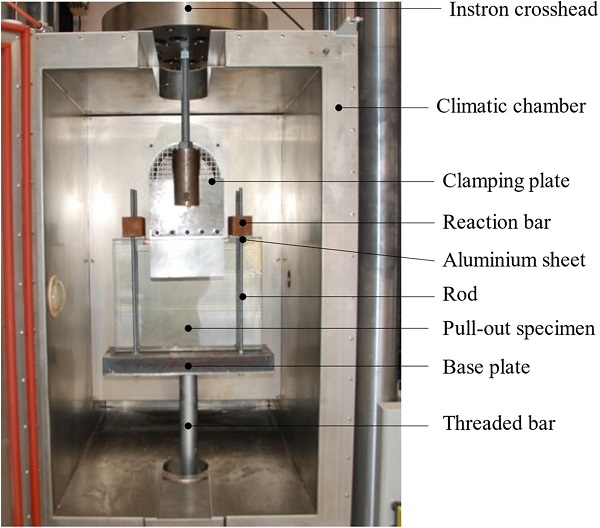
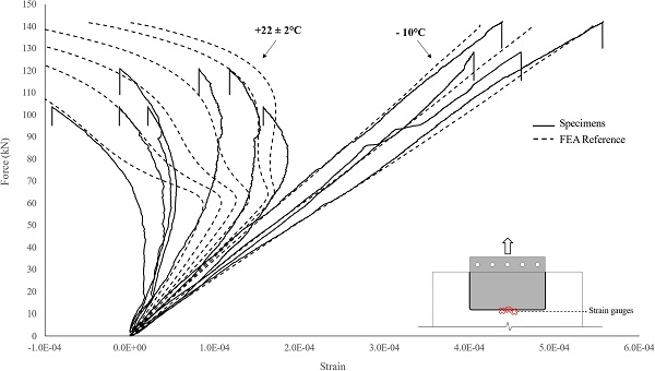
The total applied load and the crosshead displacement were recorded during testing. In addition, six transducers (three on each glass panel) were installed to measure the relative displacement between the steel insert and the glass and strain gauges were applied to the outer glass surface in the vicinity of the end face of the insert where large stress concentrations were expected to occur (Fig. 3).
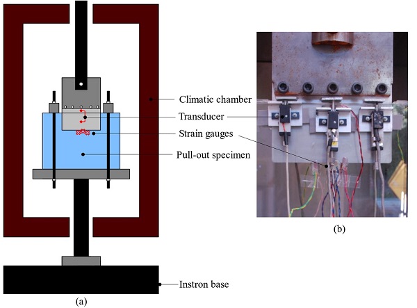
Additionally, 4 thermocouples (temperature accuracy ± 1 °C) were used to monitor the temperature before and during the tests. Specifically, two thermocouples were applied on the glass surface (one on each glass ply) and on the protruding part of the steel insert (one on each side) respectively. In all cases, loading commenced after all thermocouples had reached the intended temperature.
2.2. Experimental results and discussion
2.2.1. Load-relative displacement behaviour
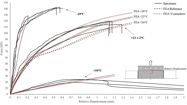
Fig. 4 shows a summary of the experimental results in the form of the load-relative displacement responses of all the tested specimens. Firstly, a qualitative comparison among the curves shows that regardless of the working temperature, the typical load–displacement response exhibits an elasto-plastic behaviour. However, the initial linear response, the strength and the failure mechanism of the connection are all markedly influenced by the temperature. It is in fact known that polymeric interlayers demonstrate softening with increasing temperature which explains the gradual connection stiffness reduction in the initial stage of the curves as the working temperature rises.
In addition, temperature also influences the adhesion quality between the interlayer and the substrates with debonding/delamination phenomena being more prevalent in warm moist conditions. This explains the experimentally observed transition of the connection failure mechanism, from brittle (glass failure) at relatively low temperatures (-10 °C and + 22 ± 2 °C [20]) to ductile (insert delamination) at higher temperatures (+50 °C).
![Fig. 4. Experimental load-relative displacement curves for each specimen tested at −10 °C, +22 ± 2 °C [20] and + 50 °C.](/sites/default/files/inline-images/Fig4_210.jpg)
In more detail, the −10 °C tested specimens demonstrated an initial linear response up to approximately an applied load of ≈ 95 kN featuring a mean stiffness (slope of load-relative displacement curves) of about ≈ 960 kN/mm. This initial linear response was followed by a plastic behaviour due to yielding of the steel insert, until an ultimate average applied force of ≈ 138 kN (ultimate relative displacement ≈ 0.2–0.6 mm) where one of the glass panels failed (Table 1).
Table 1. Primary test results at different temperatures.

Accordingly, the specimens tested at + 22 ± 2 °C [20] exhibited an initial linear response (average stiffness of ≈ 265 kN/mm) up to approximately 50 kN which was followed by a plastic behaviour up to failure (average load-bearing capacity of ≈ 116 kN and ultimate displacement ≈ 1.2 mm) due to breakage of one of the glass panels. In this instance, the stiffness reduction in the initial linear stage is the result of the progressive relaxation of the resin interlayer (i.e. time-dependent response) in conjunction with the initiation of yielding of the steel insert at approximately ≈ 95 kN (based on the FE results and experimental observations).
Finally, the + 50 °C tested specimens demonstrated an initial linear response until an average maximum applied force of ≈ 22 kN where delamination of the insert initiated leading to gradual decrease of the connection load-bearing capacity. The connection exhibited an average initial linear stiffness in the order of ≈ 35 kN/mm featuring a reduction of ≈ 96 % and ≈ 87 % with respect to that of the −10 °C and + 22 ± 2 °C tested specimens respectively.
From Table 1, it can be seen that the strength standard deviation of the connections tested at −10 °C and + 22 ± 2 °C that demonstrated glass failure is greater than that tested at + 50 °C (insert delamination) because of the relatively high probabilistic dispersion of the glass fracture strength (characteristic bending strength of heat-strengthened glass = 70 MPa [23]).
2.2.2. Failure mechanisms
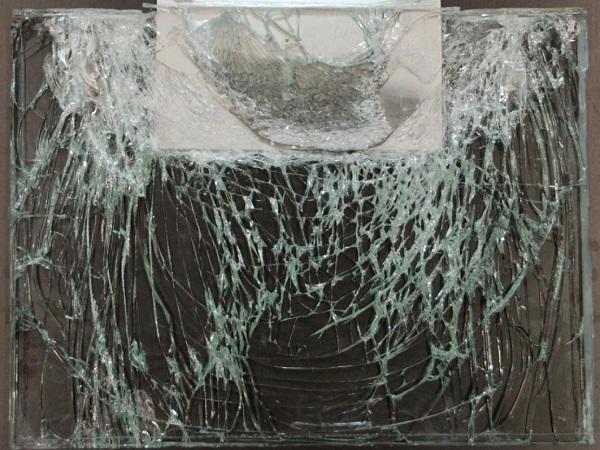
Two discrete failure modes were observed during testing that correlate to the working temperature. At + 22 ± 2 °C [20] and −10 °C, the strength of the embedded laminated connection was governed by breakage of one of the glass panels (Fig. 5). Yet, in both instances, the steel insert demonstrated considerable plastic deformation in the region of the boltholes leading to significant ductility before the brittle glass failure of the connection. From Fig. 5 it is also evident that the crack pattern of the specimens tested at −10 °C is similar to that of the specimens tested at + 22 ± 2 °C, except that the former produces a larger and denser (i.e. smaller fragments) crack pattern, due to the higher elastic strain energy that is stored and released at failure.
The energy release rate in the connections tested at −10 °C caused the glass fragments to detach from the specimens at failure, whereas at + 22 ± 2 °C the interlayer held all the glass fragments together after fracture. Careful observation of the crack pattern indicates that, for both temperatures the glass fracture originated in the region of contact between the aluminium sheets and the glass (Fig. 2). In this area, high direct compressive stresses were generated in the glass produced by the reaction forces which resulted in the formation of vertical (bearing) cracks (i.e. parallel to the loading direction, Fig. 6).
These vertical cracks instantly propagated towards the embedded area, gradually deviating until becoming nearly perfectly horizontal (i.e. orthogonal to the loading direction) at the glass surface located close to the end face of the steel insert. Additionally. the development of vertical (flexural) cracks was observed at the embedded glass zone close to the top glass edge which are attributed to the eccentricity between the reaction forces and the applied load (Fig. 6).
![Fig. 5. Failure mode of −10 °C (a), +22 ± 2 °C (b) [20] and + 50 °C (c) temperature tested specimens.](/sites/default/files/inline-images/Fig5_210.jpg)
![Fig. 6. Scheme of glass crack pattern at −10 °C and + 22 ± 2 °C [20] tested specimens (a) and of insert delamination at + 50 °C tested specimens.](/sites/default/files/inline-images/Fig6_184.jpg)
The failure mechanism of the + 50 °C tested specimens (Fig. 5) was characterised by delamination of the steel insert starting at a relatively low applied force (19–24 kN). Consequently, no signs of macroscopic yielding were detected in the steel inserts at this temperature. During testing it was evident that the debonding of the insert commenced at one of the rounded corners at the end face of the insert (Fig. 1) and gradually propagated over the entire embedded region. This eccentric delamination pattern (i.e. with respect to the loading direction) resulted in a slight rotation of the steel insert (Fig. 6).
3. Numerical (FE) investigations
3.1. Numerical (FE) model
In order to further examine and understand the experimental results, 3D Finite Element analyses of the tests were undertaken in Abaqus [22]. A brief description of the numerical (FE) model is herein provided but further details can be found in [20].
The numerical (FE) simulations were conducted as quasi-static analyses accounting for geometrical and material non-linearities. The total analyses time was divided into approximately 250 steps/increments regardless of the examined temperature. This resulted in a maximum time step of about 4 s and 0.5 s for the FE simulations at −10 °C / +22 ± 2 °C and at + 50 °C respectively.
To lower the computational cost, half of the connection (Fig. 7) was modelled utilising the symmetry along the x-axis (i.e. loading direction) and applying the relevant boundary conditions (BC). Additionally, the model was further simplified by disregarding the bolted connection (Fig. 2) and thus imposing a forced displacement rate (i.e. 1 mm/min parallel to the x-axis) directly to the bolts. The steel reaction bars were also omitted and were replaced by appropriate boundary conditions applied to the free (top) face of the aluminium sheet. For the contact between the steel insert and the bolts as well as between the glass panels and the aluminium sheet, appropriate surface to surface contact interactions were defined.
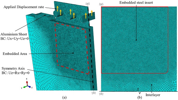
Solid brick elements were assigned throughout the entire model (i.e. glass plies, steel insert/bolts, aluminium and interlayer). In particular, reduced integration elements (i.e. C3D8R) were used in order to avoid volumetric locking phenomena that may arise when modelling almost incompressible materials as the resin interlayer (see Abaqus Analysis User’s Manual). In addition, a rigid connection (perfect bonding) was considered among the constituent materials (i.e. glass, insert and interlayer) and hence the present FE study does not explicitly capture delamination phenomena.
In order to ensure adequate accuracy of the numerical (FE) results and taking into account the experimental findings as well as the results of preliminary FE investigations (convergence study), a fine mesh size (Fig. 7) was assigned over the embedded area and in the region of the contact between the glass panels and the aluminium sheet as well as between the bolts and the insert where localised stress intensification is expected.
The glass and aluminium were modelled as linear elastic materials with elastic modulus Eglass = Ealum = 70 GPa and Poisson’s ratio vglass = 0.2 [23] and valum. = 0.30 [27]. The steel insert was modelled as elasto-plastic material with elastic modulus Esteel = 200 GPa and Poisson’s ratio vsteel = 0.3 [24]. The yield and ultimate stress were set according to data provided by the supplier as 320 MPa and 620 MPa respectively.
Based on research [25] performed by the product manufacturer (H. B. Fuller - Kömmerling), the time/temperature dependent material behaviour of the resin interlayer can be sufficiently captured via the generalised Maxwell (i.e. viscoelastic) model [28] which is mathematically represented by a Prony series:
![]()
Where G(t) is the shear relaxation modulus (function of time), G∞ is the long term shear modulus, n is the total number of Maxwell elements (i.e. linear Hookean spring connected in series with a Newtonian dashpot) and Gi, τi are the shear modulus and relaxation time respectively for each Maxwell term. The instantaneous shear modulus G0, can be estimated as:
![]()
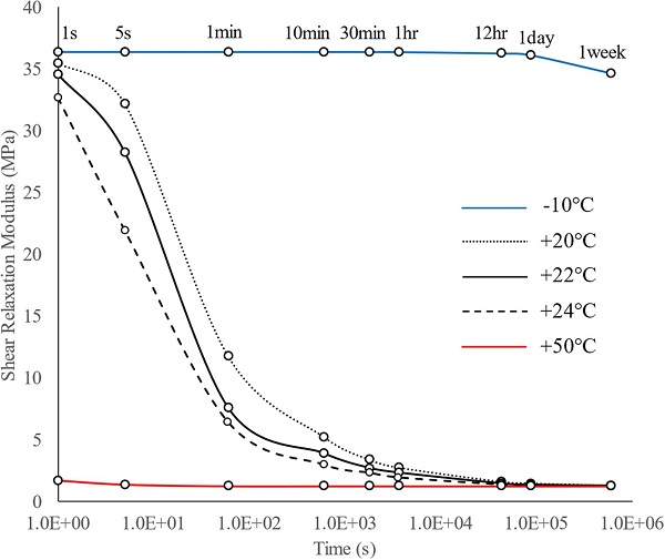
In the current study, the Prony Series parameters of the interlayer (Ködistruct LG), summarised in Table 2 at different temperatures, were defined by the manufacturer (H. B. Fuller - Kömmerling) and provided to the authors after private communication. The shear relaxation modulus (Eq. (1)) of the resin at different load durations for each tested temperature is shown in Fig. 8. Finally, in consultation with the manufacturer, the resin was modelled as isotropic with a Poisson’s ratio vresin = 0.49 that is time and temperature independent.
Table 2. Prony Series parameters (G0=36.39MPa) of the resin interlayer at different temperatures.

3.2. Numerical results and discussion
3.2.1. Numerical (FE) load–displacement curves and stress/strain state
The numerical (FE) load-relative displacement response of the connection at different temperatures shown in Fig. 9 (i.e. FEA Reference) is in good agreement with the experimental findings. Thus, the suitability of the numerical simulations is verified which enables us to examine the resulting stress/strain distribution within the connection.
Firstly, the FE simulations at −10 °C and + 22 °C (Fig. 10 and Fig. 11) indicate that the distribution of the maximum principal stresses in the glass at the experimental failure loads, closely corresponds to the glass crack pattern resulting from the physical tests (Fig. 5) considering that in brittle materials, cracks are usually formed normal to the direction of the maximum principal stresses. In particular, tensile stresses orthogonal to the loading direction (σz) are produced in the vicinity of the top glass edges at the outer and inner glass surface where vertical (flexural) cracks were formed due to the eccentricity between the reaction forces and the applied load (Fig. 6). Accordingly, tensile stresses in the loading direction (σx) are present in the region of the end face of the insert that correspond to the experimentally observed horizontal cracks in this region.
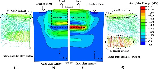
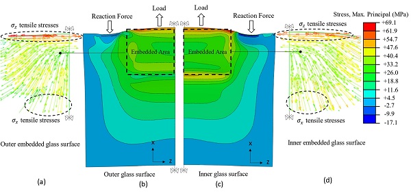
Comparison between Fig. 10, Fig. 11 shows that unlike the FE simulation at −10 °C, the FE specimen at + 22 °C experiences large stress concentrations at the maximum failure load (≈ 120 kN) which are located at the inner glass surface in the vicinity of the end face of the insert.
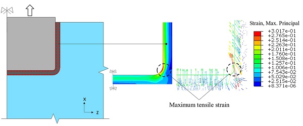
Accordingly, as seen in Fig. 12, the FE analysis results at + 50 °C correlate well with the experimental observations indicating that the delamination of the insert nucleates at the corner rounded edge of the interlayer where strain intensification occurs.
3.2.2. Load-transfer mechanisms
To further interpret the mechanical response of the connection and better explain the resulting stress fields, the load-transfer mechanisms are here briefly recalled. More details are provided in [20].
The load applied to the steel insert is transmitted to the glass panels through the interlayer via the Shear and the Tensile load transfer mechanisms (Fig. 13a):
![Fig. 13. Scheme of load-transfer mechanisms (a), (b) and amplified deformed shape of glass panels at failure load (≈ 120 kN) of FE specimen at + 22 °C [20].](/sites/default/files/inline-images/Fig13_74.jpg)
In the region of the latter mechanism (i.e. end face of steel insert), due to the incompressibility (εx+εy+εz≈0) of the resin and the high level of confinement (εz≈0), the interlayer experiences large out-of-plane contraction (εy≈-εx) (Fig. 13b) that results in out-of-plane bending of the glass panels, thereby producing direct tensile stresses (σx) at the inner surface of the glass (Fig. 13c). Additionally, in this region the stress state of the adhesive interlayer is characterised by a high tensile hydrostatic component which may lead to cohesive failure especially in case of polymeric interlayers that are susceptible to cavitation phenomena (i.e. formation of voids/bubbles in the bulk of the adhesive) [16].
In this regard, the high stress concentrations observed at the inner glass surface in the region of the end face of the insert especially for the FE specimen at + 22 °C (Fig. 10) are the result of the superposition of the tensile glass stresses (σx) generated by the Shear and the Tensile (i.e. due to local bending of the glass) load-transfer mechanism.
However, for the FE specimen at −10 °C this localised stress intensification is minor (Fig. 11). This can be rationally explained by the fact that for a given applied load, the relative displacement between the insert and the glass (Fig. 4) is markedly higher for the specimens at + 22 ± 2 °C compared to the −10 °C ones due to the lower resin stiffness (Fig. 8). As a result, the interlayer at the end face of the insert develops higher axial strain (εx) which according to the Tensile mechanism (Fig. 13b) yields greater out-of-plane bending of the glass panels. This is also explicitly confirmed by the experimental (strain gauges) measurements of the strain in the loading direction (εx) at the outer glass surface in the region of the end face of the insert.
Specifically, Fig. 14 shows that in the case of the −10 °C tested specimens, tensile strains arise which increase almost linearly with increase of the applied load up to failure. However, in the case of the + 22 ± 2 °C tested specimens, in the beginning of the tests (relatively low applied load), tensile glass strains are developed that rise with increase of the applied load but with a lower rate compared to the −10 °C tested specimens. As the load increases, these strains start to decline with some strain gauges reporting even compressive (i.e. negative) strains close to the maximum failure load which indicates large out-of-plane bending of the glass in this region.
To further examine the impact of the Tensile mechanism (Fig. 13) on the connection behaviour, a ‘contactless’ configuration (Fig. 15) was numerically (FE) analysed featuring a 2 mm clearance between the interlayer and the end face of the insert to eliminate adhesion as well as load-transfer between them.

In the first place, by comparing the FE load–displacement curves obtained from the two different FE configurations (i.e. Reference and Contactless, Fig. 9), it is observed that the contribution of the Tensile load-transfer mechanism rises with increase in temperature. This is ascribed to the reduction in interlayer stiffness as the temperature rises (Fig. 8). Namely, as the resin softens, for a given applied load, larger relative displacement is developed (Fig. 4) resulting in greater resin axial strain (εx) at the end face of the insert (Fig. 13), and therefore amplifying the contribution of the Tensile mechanism.
However, overall from Fig. 9 it is concluded that regardless of the working temperature the load transferred via the Tensile mechanism is in fact negligible especially for relatively thin inserts because the area of load-transfer of the Tensile mechanism (end face) is comparatively too small in relation to that (top/bottom faces) of the Shear mechanism.
Contrarily, the FE results revealed that the Tensile mechanism has a significant effect in terms of the resulting stress/strain state within the connection. Specifically, for the FE specimens at + 22 °C and + 50 °C that exhibited high stress and strain intensification in the region of the end face of the insert, it is found that the maximum principal tensile stress and strain of the Contactless configuration exhibit a reduction of about 42 % and 24 % respectively with respect to the Reference one (Fig. 16).
![Fig. 16. Comparison of maximum principal stresses (a) [20] and strains (b) at maximum failure load between the Reference and Contactless FE specimens analysed at + 22 °C and + 50 °C.](/sites/default/files/inline-images/Fig16_41.jpg)
4. Analytical investigations
4.1. Analytical model
A simplified analytical model (Fig. 17) is herein introduced that can sufficiently capture the time and temperature dependent characteristics of the load–displacement response of the connection observed in the experimental and numerical investigations.
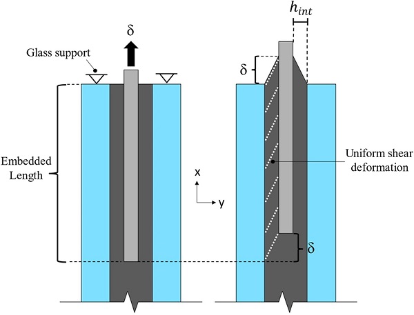
This simplified analytical model does not account for the plastic behaviour of the steel insert and also neglects the contribution of the Tensile mechanism (Fig. 13) to the total load transfer based on the aforementioned numerical (FE) results (Fig. 9).
Therefore, it is conservatively assumed that the applied load is only transferred through shear stresses over the top and bottom embedded surface (Shear load-transfer mechanism, Fig. 13) of the steel insert. In this regard, by assuming a uniform distribution of the shear stress/strain over the embedded zone, the following simplified expression can be derived:
![]()
Where F is the total applied force, Aemb (2 × 100 mm × 200 mm) is the sum of the insert surfaces subjected to shear stresses (top/bottom faces in Fig. 1) and τ is the shear stress in the interlayer.
For the simple case of a linear elastic isotropic interlayer material Eq. (3) can be expressed as:
![]()
Where G is the shear modulus of the interlayer and γ is the applied shear strain in the interlayer.
Accordingly, for an isotropic viscoelastic material, the shear stress τ(t) resulting from an applied shear strain history can be evaluated by means of the Generalised Maxwell model in the form of a convolution integral via the Boltzman’s superposition principle [28] as:
![]()
Where G(t) is the shear relaxation modulus (Eq. (1)) and γ(t) is the applied shear strain history in the interlayer.
Consequently, for a viscoelastic interlayer material Eq. (3) takes the following form:
![]()
By assuming linear elastic behaviour of the adherends (i.e. steel and glass) and considering that the interlayer stiffness is comparatively too low with respect to that of the adherends, the shear strain history γ(t) applied to the resin interlayer can be evaluated based on the relative displacement between the insert and the glass δ(t) by the following relationship:
![]()
Where δ(t) is the history of the applied relative displacement and hint (2 mm) is the thickness of the interlayer between the insert and the glass (Fig. 17).
By substituting Eq. (7) to Eq. (4), for a linear elastic isotropic material, the total applied force (F) can be evaluated for a given applied relative displacement δ as:
![]()
Accordingly, for a viscoelastic material by inserting Eq. (7) to Eq. (6) the following relationship is obtained:
![]()
As expected, unlike the case of a linear elastic material (Eq. (8)), the expression derived for a viscoelastic material (Eq. (9)) is a function of time which indicates that the overall mechanical response of the connection depends highly on the applied load duration.
4.2. Analytical results and discussion
From Fig. 8, it is noticed that at −10 °C and + 50 °C the resin shear relaxation modulus G(t) is constant and equal to the instantaneous G0 and long term G∞ shear modulus respectively for load durations relevant to that of the pull-out tests (i.e. < 30 min). Therefore, for both temperatures, the interlayer material response is considered to be linear elastic and thus Eq. (8) can be utilised for the analytical evaluation of the connection load–displacement behaviour.
Specifically, Fig. 18 shows that in the case of the −10 °C tested specimens, the analytical estimation is in satisfactory agreement with the experimental and numerical (FE) load–displacement curves until a maximum applied force of approximately 95 kN, with analytical and average experimental values of the initial linear stiffness being around 730 kN/mm and 960 kN/mm respectively. At this load level (95 kN) the steel insert starts to yield locally and thus the actual applied shear strain in the interlayer γ(t) is no longer directly proportional to the measured relative displacement between the insert and the glass δ(t) (Eq. (7)).
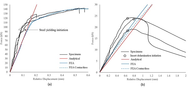
Similarly, for the specimens tested at + 50 °C, the analytical prediction (Fig. 18b) provides a good fit to the experimental and numerical (FE) data up to the applied load where insert delamination commences. In particular, the experimental and analytical initial linear connection pull-out stiffness were estimated in the range of 35 kN/mm and 25 kN/mm respectively that equates to an underestimation of about 29 %. This is mostly attributed to the contribution of the Tensile mechanism to the total load transfer which was considered negligible in the analytical model, but can become more significant at relatively high temperatures (Fig. 9).
Unlike −10 °C and + 50 °C, Fig. 8 shows that at + 22 ± 2 °C the resin interlayer exhibits large relaxation for load durations relevant to that of the pull-out tests (i.e. < 30 min). Hence, in this case the mechanical response of the connection is time-dependent (Eq. (9)) and specifically it is governed by the history of the relative displacement between the insert and the glass δ(t) summarised in Fig. 19 for each tested specimen. In order to evaluate the connection pull-out response, these experimental relative displacement time histories are first approximated by six degree polynomials (Eq. (10), Fig. 19) and are then implemented in Eq. (9).
![]()
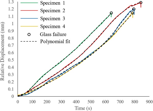
Where t is the time and a, b, c, d, e, f and g are the polynomial coefficients summarised in Table 3 along with the coefficient of determination (R²) for each polynomial fit.
Table 3. Determination (R²) and polynomial coefficients of the history of the relative displacement δ(t)

The analytical predictions for each specimen tested at + 22 °C ± 2 °C are presented in Fig. 20. In general, it is observed that the connection response is adequately captured within the examined temperature range (+22 °C ± 2 °C). In more detail, the experimental response of Specimen 1 (Fig. 20a) is better approximated by considering the resin properties at + 22 °C while the behaviour of the other specimens is better captured considering the interlayer properties at + 20 °C. Additionally, as expected the analytical model overestimates the connection response for loads higher than about ≈ 95kN. As mentioned above, at this applied load level, local yielding of the steel insert commences and thus the actual applied shear strain in the resin interlayer is significantly lower from that calculated by Eq. (7).
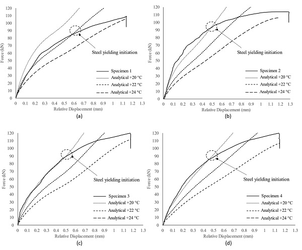
Overall, it is concluded that the proposed simplified analytical model (Eq. (8), (9)) offers a satisfactory prediction of the connection load–displacement response under pull-out loading. It does so with significantly less effort and cost than 3D FE modelling or physical testing, thereby providing a useful tool for early stage design of such connections for real world applications.
5. Conclusions
In this study, the mechanical response of an embedded liquid-laminated glass connection subjected to pull-out loading at different temperatures was assessed by means of experimental tests, numerical (FE) simulations and simplified analytical models.
Firstly, the experimental results showed that temperature has a major impact on the structural behaviour of the connection. Specifically, it was found that as long as the working temperature does not significantly exceed the room temperature threshold (+22 ± 2 °C), the failure mode of the connection is characterised by glass fracture whereas beyond this limit delamination phenomena govern the connection failure mechanism. It was also shown that the insert can be sized to produce a significant degree of plastic deformation in the connection prior to reaching the ultimate load-bearing capacity which is desirable for robust engineering design.
The numerical (FE) simulations conducted in Abaqus revealed the resulting complex stress state within the connection which is characterised by large stress/strain concentrations whose intensity also depend on the working temperature. Overall, the numerical (FE) distribution and direction of the stresses/strains correlate well with the experimental measurements (i.e. strain gauges and load–displacement behaviour), the experimental glass crack pattern and the location of the observed insert delamination.
Finally, based on the experimental and numerical (FE) data, a simple analytical tool was developed that offers satisfactory accuracy in predicting the pull-out load–displacement response of the connection, thereby providing a preliminary insight of the connection performance which can be a useful aid in the engineering design of these connections for real-world applications.
Declaration of Competing Interest
The authors declare that they have no known competing financial interests or personal relationships that could have appeared to influence the work reported in this paper.
Acknowledgements
The authors wish to express their gratitude to H. B. Fuller-Kömmerling, seele and Arup for providing the materials and technical advice required for this paper and to TTEC GmbH for providing technical support for the manufacture of the specimens. This research project is funded jointly by the EPSRC (UK) Doctoral Training Account, H. B. Fuller-Kömmerling and seele.
Data availability
Data will be made available on request.


