Authors: S. C. Angelides, J. P. Talbot & M. Overend
Source: Glass Structures & Engineering, volume 7
DOI: https://doi.org/10.1007/s40940-022-00168-y
Abstract
Laminated glass panels are increasingly installed in glazed façades to enhance the blast protection of buildings. These ductile panels offer residual bending resistance following the fracture of the glass layers, due to the composite action of the attached glass fragments in compression and the interlayer in tension. Three-point bending tests performed previously on laminated glass specimens at low temperature, which aimed to simulate the effects of high strain-rate due to the time-temperature dependency of the interlayer, demonstrated an enhancement of the ultimate load capacity by two orders of magnitude compared to that at room temperature. These tests were performed on specimens with an idealised fracture pattern, by pre-fracturing cracks at a uniform spacing of 20 mm, aligned in both glass layers. Under blast loads, however, a random pattern of irregular fragment sizes occurs, with the cracks not always aligned in the two glass layers.
Additionally, the plastic hinge location within each specimen coincided with the point of application of the load, which may have influenced the results. This paper addresses these concerns by reporting on further low-temperature tests that have considered four additional pre-fractured patterns in both three- and four-point bending. The results demonstrate that the bending moment capacity of the specimens is unaffected by the number and size of the glass fragments, and by the choice of the loading rig. An enhancement of the bending capacity is consistently observed for specimens with misaligned cracks that is almost twice that of specimens with aligned cracks. This suggests that the idealised pattern with aligned cracks, considered in previous work, results in a lower-bound estimate of the bending capacity for panels with random fracture patterns formed under blast loading.
1 Introduction
During a blast event, the façades of buildings act as the first barrier of defence in protecting occupants, by preventing the blast waves from penetrating the interior. Resilient glazed façades, capable of offering such protection, can be achieved by using ductile, laminated glass panels instead of inherently brittle, monolithic glass panels. These composite sandwich panels, consisting of multiple glass layers laminated with a transparent polymer interlayer, hold the glass fragments in place and offer enhanced capacity by providing resistance to the blast wave after the glass layers have fractured. Although many interlayer types are available, the UK Centre for the Protection of National Infrastructure recommends using only Polyvinyl butyral (PVB) and ionomer interlayers for blast protection (CPNI 2019). The focus here is on the former, as this is the most common interlayer used in building façades.
The lamination of the glass layers and PVB results in a strong adhesion bond forming between the glass layers and the PVB. Following the fracture of the glass layers, it is this bond that retains the glass fragments on the interlayer, thereby reducing the risk of glass-related injuries during blast events. This bond is not a universal constant and is affected by environmental factors (Butchart and Overend 2012, 2013, 2017; Samieian et al. 2018). Furthermore, some fragments invariably delaminate at large deflections (Hooper 2011; Pelfrene et al. 2016).
An additional benefit of the glass-PVB bond is that the attached glass fragments contribute to the post-fracture capacity of the panel, resulting in a composite bending action that involves the interlayer, working in tension, together with the glass fragments that come into contact as the panel deforms, working in compression. Although this bending capacity has been experimentally demonstrated to be negligible under quasi-static loads (i.e. low strain rates), compared to the capacity of the intact panel (Kott and Vogel 2003, 2004, 2007), the response is fundamentally different at the high strain-rates associated with blast loading, due to the viscoelastic nature of PVB. It should be noted that this applies for glass fragments that are unconfined, as the contribution of the fractured glass is non-negligible, even at very low strain rates, if confined between layers of unfractured glass (Overend et al. 2014).
An enhanced PVB stiffness is observed at high strain-rates, and the shape of the stress–strain diagram resembles an elastic–plastic material (Kott and Vogel 2003; Bennison et al. 2005; Iwasaki et al. 2007; Morison 2007; Hooper et al. 2012a; Zhang et al. 2015; Chen et al. 2018; Botz et al. 2019a). This often leads to the misleading terminology of ‘elastic and ‘plastic’ when referring to the response of the PVB. Although this is also adopted in this paper, these terms only refer to the shape of the stress–strain diagram, as the response remains viscoelastic in practice. The term ‘yield stress’ therefore refers to the stress at which a significant change in slope of the stress–strain diagram is observed, rather than the onset of true plasticity. This distinct point in the stress–strain diagram is only observed at high strain-rates or low temperatures.
By drawing comparisons with the traditional analysis methods for reinforced concrete, which also consists of a brittle material (concrete) reinforced with a ductile one (steel) to carry tension, analytical models were derived by Angelides et al. (2019) for the post-fracture bending moment capacity of laminated glass at high strain-rates. The limit of the elastic response of PVB, i.e. the yield stress, was considered in the derivation of the elastic capacity (M₃—identified as Stage 3 by Angelides et al.). Note that Stages 1 and 2 in the models by Angelides et al. correspond to the pre-fracture stage (i.e. all glass layers are intact) and to the stage were only one glass layer has fractured, respectively. The transformed section approach was adopted and a panel with two fractured glass layers was considered. The contribution of the bottom glass layer (i.e. the layer not impacted by the blast wave, or the ‘tension’ glass layer) was ignored, as this is in tension for the positive blast phase due to the sagging response.
The top glass layer (i.e. the layer impacted by the blast wave, or the ‘compression’ glass layer) was idealised as a uniform homogeneous material, due to the small size of the glass fragments formed under blast loads as a result of the high strain energy stored in the panel prior to fracture (Overend et al. 2007; Haldimann et al. 2008; Zaccaria and Overend 2012, 2020). It was considered that the fracturing of the glass layers occurs over a very short time-frame, relative the post-fracture response of the panel, and may therefore be idealised as a form of instantaneous ‘phase change’ in the material. It is, however, noted that the fracture pattern may differ even for panels with the same geometry and under identical blast loads, due to the random surface flaws developed in the glass during manufacturing, installation and service-life (Haldimann et al.). The location of the critical flaw (i.e. the flaw at which cracking begins) therefore varies and does not always coincide with the location of the highest internal bending moment, as shown in Fig. 1a. This was also observed in the blast tests performed by Osnes et al. (2019).

Following the yielding of the PVB, the plastic capacity (M₄ – identified as Stage 4 by Angelides et al.) was derived by Angelides et al. by applying moment equilibrium about the plastic neutral axis at the instant when the cross-section has no reserve moment capacity and a plastic hinge forms. At this instant, the compressive force in the top glass layer initiates crushing of the glass fragments and leads to further local fracture at the location of the highest internal bending moment, in addition to the initial global fracture of the glass, as shown in Fig. 1b. The initial global pattern occurs separately in each glass layer when the tensile stresses, developed from the combined out-of-plane bending and in-plane membrane response of the panel, exceed the fracture stress (Fig. 1a). In contrast, the subsequent local fracture due to crushing occurs only in the ‘compression’ glass layer (Fig. 1b). The differences between the global and local fracture are evident when comparing the fracture patterns from blast tests on both monolithic glass panels (Johns 2016; Monk 2018) and laminated glass panels (Osnes et al. 2019). No crushing failure is observed in the former, whereas the evolution of the fracture pattern in laminated glass at different time stamps shows further cracking after the initial fracture pattern has formed.
These analytical models were later experimentally validated by Angelides et al. (2020), who performed three-point bending tests (3-PBT) on pre-fractured laminated glass specimens at −100 °C. The tests were initially performed on specimens (labelled as CS1 by Angelides et al.) with two glass layers (with tG = 3 mm) and a single interlayer (tPVB = 0.38 mm). The low temperature aimed to simulate the effects of high strain-rate due to the time-temperature dependency of the viscoelastic PVB, which was demonstrated by Angelides et al. using Chen’s et al. (2018) high-speed tensile test results at different temperatures. By deriving a linear time-temperature equivalence mapping for PVB, similar to the work of Siviour et al. (2005) for other polymers, Angelides et al. mapped the maximum strain-rate from the 3-PBT at −100 °C–25 °C, calculating a mapped strain-rate of 25 s⁻¹.
This value was selected because it is representative of laminated glass panels in typical blast conditions, as evidenced by Morison’s (2007) and Hooper’s (2011) full-scale blast tests, where mean strain-rates ranging from 7.6 to 30 s⁻¹ were recorded. This procedure was chosen to validate the models due to its advantage of decoupling inertia loading from the effects of strain-rate, which is not possible in traditional dynamic tests. The results of Angelides et al. showed an enhancement of the ultimate load capacity by two orders of magnitude compared to that at room temperature. This demonstrated the significance of PVB stiffening at high strain-rates to the residual post-fracture bending capacity that is often ignored in existing blast analysis methods of laminated glass panels (Angelides and Talbot 2021). The results also consistently showed enhanced capacities for specimens with thicker PVB and glass layers (labelled as CS2: tG = 3 mm/tPVB = 1.52 mm/tG = 3 mm and CS3: tG = 6 mm/tPVB = 1.52 mm/tG = 6 mm by Angelides et al.), which validated the analytical predictions of bending theory.
The experimental work of Angelides et al. considered an idealised fracture pattern, by pre-fracturing cracks at a uniform spacing of 20 mm, as shown in Fig. 2a. This allowed a direct comparison between tests. Under blast loads, a random pattern of irregular fragment sizes occurs, as described above and shown in Fig. 2b, with the cracks not always aligned in the two glass layers. Additionally, the plastic hinge location (i.e. mid-span) within each specimen coincided with the point of application of the load from the 3-PBT rig, which may have influenced the results. This paper addresses these concerns and aims to demonstrate that the post-fracture bending capacity previously derived by Angelides et al. for an idealised fracture pattern represents a lower-bound value for panels with more realistic, random patterns. To achieve this, low-temperature bending tests are performed on a series of different pre-fractured patterns to assess the influence of the glass fragment size and crack alignment on the bending moment capacity. Additionally, four-point bending tests (4-PBT) are also performed to demonstrate that the experimental results are unaffected by the choice of loading rig. The present study is limited to:
- PVB laminated glass specimens with two glass layers;
- three different, pre-fractured patterns with cracks aligned in both glass layers (single crack at mid-span, three cracks at uniform spacing, and a single crack offset from mid-span); and
- one pre-fractured pattern with crack misalignment in both glass layers.

2 Experimental method
This section introduces the glass specimens and pre-fractured patterns considered, followed by a description of the bending tests performed with the two different loading rigs. The derivation of the post-fracture plastic bending moment capacities from the experimental results is then explained.
2.1 Description of laminated glass specimens and pre-fractured patterns
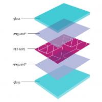
The test specimens consisted of laminated glass made from two layers of annealed glass (tG = 3 mm), with polished edges (to minimise secondary cracking), and a PVB interlayer (tPVB = 0.38 mm). The overall geometry of the specimens (total length L = 200 mm, width B = 55 mm) was determined by the available space within the environmental chamber and the need to ensure a sufficiently high length-to-thickness ratio for simple bending; the thickness of each layer was dictated by manufacturing constraints. The specimens were laminated in a commercial, glass laminating autoclave to BS EN ISO 12543-2, using the same glass and PVB products for all specimens. The specimens are identical to the CS1 specimens considered in the experimental investigation of Angelides et al. (2020).
To ensure controlled and repeatable fracture patterns, the specimens were pre-fractured before testing, by first scoring both glass faces with a hand-held glass cutter (hardened steel) and then impacting them at the location of the score, from both sides, to produce full-thickness cracks in each glass layer. Similar methods of pre-fracturing have been described by Nhamoinesu and Overend (2010), Hooper (2011), Samieian et al. (2018) and Angelides et al. (2020).
To investigate the influence of the fragment size on the post-fracture bending capacity, specimens with three different pre-fractured patterns were tested. These are illustrated in Fig. 3a–c. The baseline pre-fractured pattern (A-1) has a single transverse crack at the mid-span location, with the cracks in each glass layer aligned one above the other (Fig. 3a). The second pattern (A-2) has two additional cracks, located 30 mm away on either side of the mid-span location (Fig. 3b). The final pattern (A-3) has a single transverse crack located 30 mm from the mid-span location, again, with the cracks in each glass layer aligned one above the other (Fig. 3c). Pattern A-2 and A-3 enable the investigation of the influence of smaller and unequal fragment sizes, respectively, compared to the baseline pattern. The results from all three patterns are also compared to the idealised fracture pattern considered by Angelides et al. (2020), which, in comparison to the baseline pattern, has four additional cracks at 20 mm spacing from the mid-span location, as discussed in Sect. 1 and shown in Fig. 3e.
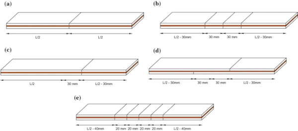
To examine the influence of the crack alignment between the two glass layers, an additional pre-fractured pattern was considered (A-4). This is shown in Fig. 3d and is similar to pattern A-3 but with the crack in the bottom glass layer located 30 mm from the mid-span location in the opposite direction to the crack in the top glass layer (i.e. a crack misalignment of 60 mm).
Each specimen was pre-fractured immediately before testing, to avoid the need for controlled storage of the specimens. This minimised the influence of any moisture on the exposed PVB, which could have led to a degradation in material properties (Butchart and Overend 2012, 2013, 2017; Botz et al 2019b; Botz 2020).
2.2 Choice of loading rig
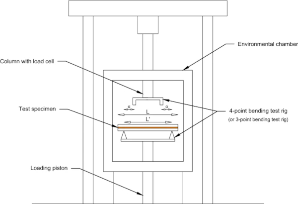
The experiments were performed in Cambridge University Engineering Department using a Schenck Hydropuls PSA testing machine within an environmental chamber. The PSA machine is typically used for axial testing, but bending tests can also be performed by incorporating 3-PBT and 4-PBT rigs, as shown in Fig. 4. The span L′ between the simple-supports is 110 mm, with the load applied mid-span, for the 3-PBT, and at a distance α = 26 mm from each support for the 4-PBT (i.e. shear span = 26 mm and load span = 58 mm in 4-PBT). The maximum load cell capacity is 10 kN, and the displacement is measured from the movement of the loading piston. Temperatures as low as -196 ˚C can be achieved in the chamber using a thermostatically regulated supply of liquid nitrogen.
A summary of the experimental work performed is shown in Table 1. The 3-PBT were carried out at a controlled temperature of −100 °C, repeating each test three times for each pre-fractured pattern (A-1–A-4) to obtain confidence in the experimental results. Displacement-controlled tests were performed at a rate of 0.1 mm/min, with the applied load measured by the load cell. These conditions are identical to the previous experimental work of Angelides et al. (2020) and correspond to a mean mapped strain-rate of 25 s⁻¹, which is typical of laminated glass panels under blast loads at ambient temperature. The temperature in the environmental chamber was controlled through an internal thermometer and verified with a thermocouple placed near the specimens. To ensure that the specimens themselves reached the desired temperature, a second thermocouple was initially bonded to a sample specimen to establish the time required for its temperature to reach that of the chamber. This time was found to be approximately 10 min, and this acclimatisation period was used in all specimens prior to testing. To verify that the PVB itself was also cooled to the desired temperature, a thermal camera was used (Angelides et al. 2020).
Table 1 Testing conditions of laminated glass specimens for each pre-fractured pattern - Full size table

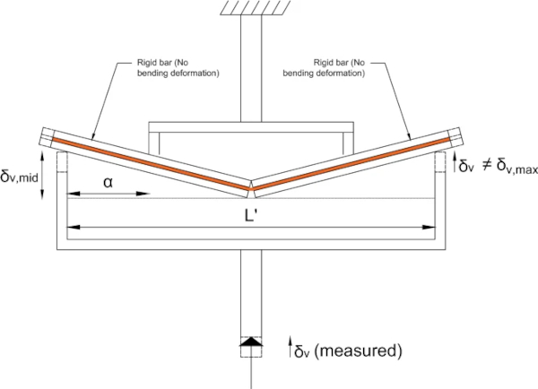
To demonstrate that the experimental results are unaffected by the choice of the loading rig, 4-PBT were repeated for patterns A-1 and A-2. Additionally, to validate the enhancement in ultimate load capacity at low temperatures, as observed by Angelides et al. (2020) and discussed in Sect. 1, bending tests for pattern A-1 were also performed at room-temperature using the 4-PBT rig at the same displacement-rate. Again, each test was repeated three times. For the simple deflected shape of pattern A-1, in which the sections either side of the crack are treated as rigid, the mid-span deflection was derived from the recorded displacement by considering similar triangles
![]()
as shown in Fig. 5.
2.3 Plastic moment capacity
A key objective of the experimental work is to demonstrate that the post-fracture bending moment capacity previously derived by Angelides et al. (2020) for an idealised fracture pattern represents a lower-bound value for panels with random fracture patterns. This is achieved by comparing the idealised capacity to the capacities of specimens with different glass fragment sizes (patterns A-1–A-3) and with crack misalignment (pattern A-4). The bending moment capacities (M₄,i—i.e. for Stage 4, as defined by Angelides et al. 2019) are derived from the experimentally measured ultimate load (P₄,i – i.e. for Stage 4), by applying the upper-bound theorem of plasticity (Jones 2011). The ultimate load refers to the maximum load recorded.
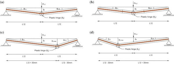
This corresponds to the instance the glass crushes and a plastic hinge forms (Angelides et al. 2020). For the simply-supported, statically determinate specimens considered here, the bending moment distribution is governed by equilibrium alone and is not affected by the stiffness variation along the span resulting from the pre-fractured cracks. As the cross-sections with cracks are significantly weaker than the non-fractured sections, plastic hinges are more likely to form at these locations first. Based on this assumption, the anticipated collapse mechanisms from the 3-PBT are plotted in Fig. 6, illustrating how each specimen behaves as two rigid bars connected via the hinge. Figure 6a, c show the anticipated collapse mechanisms for patterns A-1 and A-3, respectively, with the plastic hinges drawn at the location of the single crack. For pattern A-2 (Fig. 6b), which has multiple cracks, the plastic hinge is expected to form at the mid-span crack, as this experiences the highest internal bending moment. This assumption is supported by the experimental work of Angelides et al. (2020), where PVB tearing was consistently observed in the mid-span crack for the pre-fractured specimens with 5 cracks.
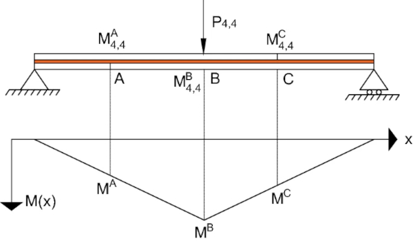
For pattern A-4 (Fig. 6d), similar to pattern A-3, the crack locations do not coincide with the location of the maximum internal bending moment, as shown in Fig. 7 (i.e. Mᴬ=Mᶜ<Mᴮ). However, the moment capacities at the crack locations are weaker than the non-fractured section at mid-span (i.e. Mᴬ₄,₄<Mᴮ₄,₄ and Mᶜ₄,₄<Mᴮ₄,₄). Therefore, as with pattern A-3, it is expected that the plastic hinge will form at a crack location, despite the mid-span non-fractured section experiencing a higher bending moment. Due to the sagging response, it is expected that an additional crack will form in the ‘compression’ glass layer and align with the existing crack in the ‘tension’ glass layer (i.e. location A shown in Fig. 7). A plastic hinge is therefore expected to form at the location of the crack in the ‘tension’ glass layer. The validity of this assumption will be re-examined in Sect. 4.3, which discusses the experimental results for pattern A-4.
The derivation of the plastic moment capacities from the experimental results, for each pre-fractured pattern, is summarised in “Appendix A”. The resulting analytical expressions are given below in Eqs. 1 and 2, for the 4-PBT and the 3-PBT respectively:

where d = 30 mm.
3 Results
This section presents the results of the experimental work described in Sect. 2. Firstly, a comparison of the ultimate loads recorded at low and room temperature with the 4-PBT rig is presented for the specimens with pre-fractured pattern A-1. The ultimate loads recorded at low temperature with the 3-PBT rig are then compared for the four pre-fractured patterns (A-1–A-4). Finally, these results are used with Eqs. 1 and 2 to derive the plastic moment capacities for each pre-fractured pattern, which are then compared to the capacity of the idealised pattern considered by Angelides et al. (2020).
3.1 Four-point bending tests
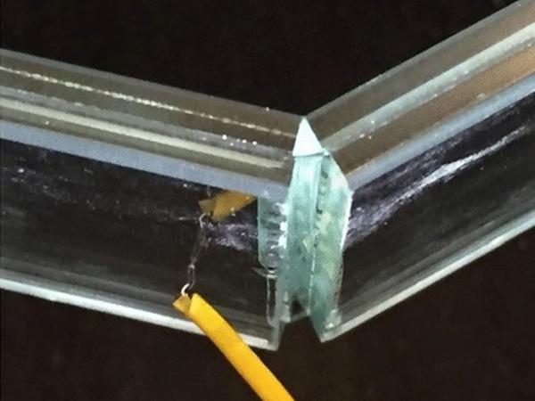
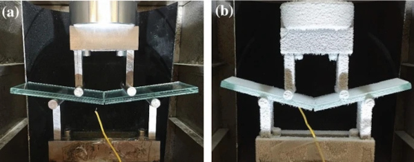
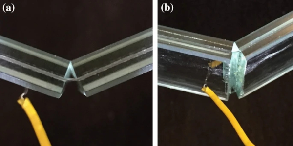
Figure 8 provides an overview of the 4-PBT. At low temperature, for both pre-fractured patterns (A-1 and A-2), the tests concluded with brittle tearing of the PVB at the mid-span crack. At room temperature, the response is more ductile, with the A-1 specimens able to deform to large deflections without tearing the PVB, as shown in Fig. 9. In this case, the tests were terminated when the applied load reached a plateau and the maximum load recorded was defined as the ultimate loading. The average test duration was 19 min at low temperature and 62 min at room temperature.
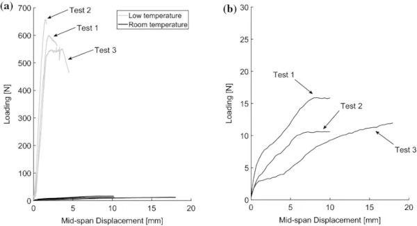
The ultimate load measurements from the 4-PBT are summarised in Table 2, and the recorded load vs mid-span displacement response from all three A-1 specimens, at both temperatures, is presented in Fig. 10. It was challenging to produce identical fracture patterns and to maintain a constant temperature throughout the duration of the tests. In addition, there is inherent variability in the material properties. Nevertheless, the low-temperature results show a good consistency across the three, nominally identical tests. The results at room temperature vary more significantly in relative terms. The accuracy of these was primarily limited by the sensitivity of the available load cell, which had a capacity 10 kN, far in excess of the ultimate loads measured (10–16 N). Nevertheless, these results are considered sufficient for the assessment of the low temperature, and therefore high strain-rate, effects. A further limitation may have been the inability to control precisely the room temperature, but this is considered to have had a minor effect.
Table 2 Recorded ultimate loads and observed failure mechanisms from the low- and room-temperature 4-PBT of the specimens with A-1 and A-2 pre-fractured patterns - Full size table
3.2 Three-point bending tests
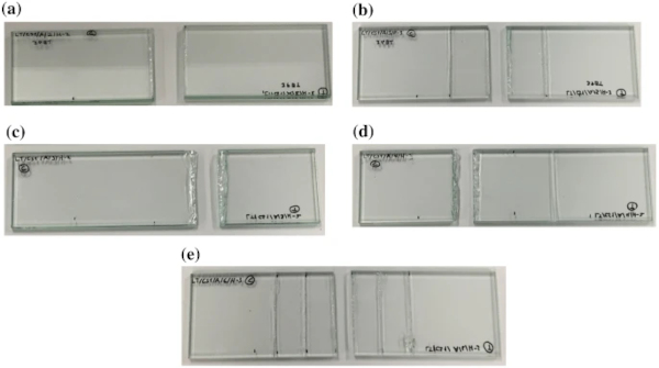
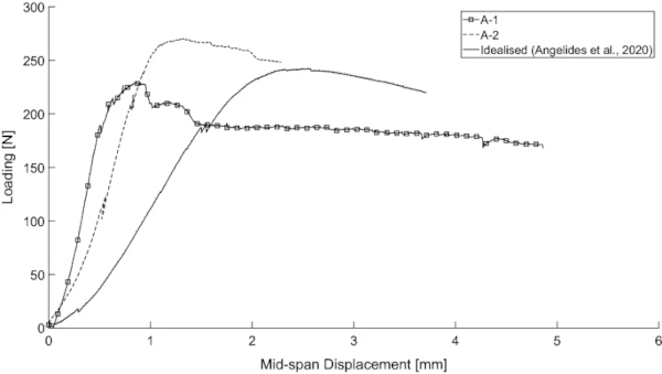
The ultimate loads recorded from the low-temperature 3-PBT for each pre-fractured pattern (A-1–A-4) are presented in Table 3. The average test duration was 25 min. A good consistency is observed between the specimens tested, except for Test 2 of pattern A-3. A post-test assessment of this specimen revealed that poor crack alignment between the top and bottom glass layers, from the pre-fracturing stage, most likely influenced the results. The failure mechanisms were consistent for each pre-fractured pattern, with the PVB tearing at the same location for all three specimens tested. These are shown in Fig. 11 and summarised in Table 3, with the former also including the failure mechanism for the idealised pre-fractured pattern with 5 cracks considered by Angelides et al. (2020) (Fig. 11e). For pattern A-1 and A-2, the failure mechanisms were identical to the specimens tested with the 4-PBT rig, as discussed in Sect. 3.1, with the PVB tearing at the mid-span crack. As predicted in Sect. 2.3, for pattern A-4, failure occurred at the location of the pre-fractured crack in the ‘tension’ glass layer. A comparison of the load vs mid-span displacement response recorded from the 3-PBT for patterns A-1, A-2 and the idealised case considered by Angelides et al. is shown in Fig. 12. For clarity, only one specimen from each case is presented.
Table 3 Recorded ultimate load and observed failure mechanism from the low-temperature 3-PBT - Full size table
3.3 Plastic moment capacities
The ultimate load measurements cannot be compared directly for all patterns, as the 3PBT and 4PBT loading rigs give rise to different states of stress (specifically, bending moment distributions) in the specimens. Instead, these measurements are used to derive the post-fracture plastic moment capacity (M₄) for each pre-fractured pattern, as described in Sect. 2.3. The derived plastic moment capacities using Eqs. 1 and 2 are shown in Tables 4 and 5. The former compares patterns A-1, A-2 and A-3 that aimed to assess the influence of the size of the glass fragments, while the latter presents the derived capacity for specimens with crack misalignments (pattern A-4). In both tables, the capacity for the idealised pattern considered by Angelides et al. (2020) is included for comparison.
Table 4 Comparison of the plastic moment capacities (M₄) for patterns A-1, A-2 and A-3 with the capacity for the idealised pattern considered by Angelides et al. (2020) - Full size table
Table 5 Comparison of the plastic moment capacity (M₄) for pattern A-4 with the capacity for the idealised pattern considered by Angelides et al. (2020) - Full size table
4 Discussion
The influence of the loading rig on the experimental results is first evaluated, followed by a discussion of the effects of the glass fragment size and the crack alignment on the post-fracture plastic moment capacity.
4.1 Effect of loading rig
The low-temperature tests for patterns A-1 and A-2 were performed with both 3-PBT and 4-PBT rigs. As shown in Table 4, there is good consistency between the plastic moment capacities resulting from the two loading rigs for both pre-fractured patterns. It is therefore concluded that both loading rigs produce reliable results, and there is no significant experimental error induced by the 3-PBT rig, more specifically, the fact that the point of application of the load in the 3-PBT coincides with a pre-fractured crack does not affect the results.
A significant enhancement of the ultimate load capacity of the fractured glass at low temperature, compared to that at room temperature, is observed in Table 2 and Fig. 10 for pattern A-1. A stiffer response, resembling a bi-linear, elastic–plastic load–deflection curve with a brittle failure is noted for the low-temperature tests, whereas at room temperature the response is more flexible and viscoelastic. This enhancement, and the fundamentally different response at low temperature, agrees with the 3-PBT results presented by Angelides et al. (2020). Given the observed time-temperature dependency of PVB, this is expected to translate to a similar enhancement at the high strain-rates associated with typical blast loading. However, using the 4-PBT rig instead for pattern A-1, which has a single pre-fractured crack at mid-span, it has been possible to investigate in isolation the room-temperature failure mechanism of laminated glass at the crack location. As shown in Fig. 9, a ductile response is observed with the PVB spanning across the crack.
There is no crushing of the glass fragments in the top layer, even at large deflections, and therefore plastic hinges do not form. As discussed by Angelides et al. (2019), plastic hinges form in fractured laminated glass specimens at high strain-rates, when the ‘compressive’ glass layer crushes, following the yielding of the interlayer. At that instance, the cross-section has no reserve moment capacity. The failure mechanism is significantly different at low temperature and, as a result, at high strain-rates. As shown in Fig. 11, a brittle PVB failure is consistently observed at low temperature, with crushed glass fragments visible at the plastic hinge vicinity. However, a more ductile response is anticipated at the high strain-rates associated with typical blast loading, as the brittle failure observed is mainly attributed to the stiffer adhesion bond resulting from the low temperature, which inhibits the delamination of the glass fragments. This leads to the rapid accumulation of strains and the subsequent premature tearing of the PVB, as previously discussed by Angelides et al. (2020).
4.2 Effect of glass fragment size
Table 4 compares the plastic moment capacity of the idealised pattern with the capacities of three pre-fractured patterns. These results show that the moment capacities are unaffected by the number and the size of the glass fragments. Capacities with similar values are noted for specimens with two (pattern A-1), four (pattern A-2) and six glass fragments, with the latter corresponding to the results presented by Angelides et al. (2020). There is a slightly larger capacity observed for specimens with unequal glass fragments (pattern A-3), but this is attributed to the higher ultimate load measurement of Test 2 that was previously discussed in Sect. 3.2. The remaining measurements of pattern A-3 (i.e. Test 1 and 3) result in similar capacities to the specimens pre-fractured with equal fragment sizes (patterns A-1 and A-2). Therefore, the consistent moment capacity values observed here for four different pre-fractured patterns suggest that the capacity of laminated glass panels with irregular glass fragment sizes that are perfectly aligned in the two glass layers, can be approximated from specimens with idealised pre-fractured patterns.
On the other hand, the bending stiffness of the specimens is affected by the number of cracks. This can be observed from Fig. 12, where the load vs mid-span displacement diagrams from the low temperature 3-PBT of patterns A-1, A-2 and the idealised cased considered by Angelides et al. are compared. The ultimate loading of the three specimens is of the same order. In contrast, the slope of each curve, and consequently the bending stiffness of each pre-fractured pattern, varies. A stiffer response is observed for the base case (A-1), which has a single mid-span crack, while a more flexible behaviour is evident for the idealised case with 5 cracks. The bending stiffness for case A-2, which has 3 cracks, is in-between the two cases. A more flexible response is therefore anticipated for laminated glass panels that will fractured in multiple glass fragments under blast loading.
4.3 Effect of crack alignment
Table 5 compares the plastic moment capacity derived for specimens with misaligned cracks between the two glass layers (pattern A-4) with the capacity for an idealised pattern with perfect crack alignment, as considered by Angelides et al. (2020). The moment capacity for pattern A-4 was calculated based on the assumed collapse mechanism shown in Fig. 6d, which considered a single plastic hinge forming at the location of the crack in the ‘tension’ glass layer. The consistent tearing failure observed at the assumed plastic hinge location for all three specimens with the A-4 pattern, shown in Fig. 11d, validates the collapse mechanism considered. In all three specimens, a new crack formed in the ‘compression’ layer and aligned with the pre-fractured crack in the ‘tension’ glass layer.
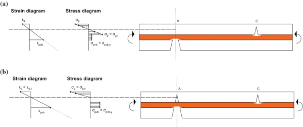
A significant enhancement of the capacity is consistently observed in Table 5 for the specimens with misaligned cracks, which is almost twice the value associated with specimens with aligned cracks. This enhancement is attributed to the contribution of the unfractured glass layer at the crack location. This influences the plastic bending stress distribution in the specimens at the crack location, as shown in Fig. 13a, and consequently, the plastic bending moment capacity, which is derived by applying moment equilibrium about the plastic neutral axis (Angelides et al. 2019). Therefore, an additional crack first needs to form in the unfractured glass layer, as shown in Fig. 13b, for the specimens to fail. This will occur when the tensile stress in the glass layer exceeds the tensile fracture strength of glass (σg=σg,t). At this stage, the tensile stress in the interlayer is below the yield stress (σpvb<σpvb,y). This additional bending moment required to fracture the glass layer is the reason for the enhanced capacity in comparison to the cases with aligned cracks in the two layers.
Due to the sagging response, the moment required for a new crack to form is higher at location C shown in Fig. 13a, compared to location A, as the top glass layer contributes in compression from the glass fragments coming into contact as the panel deforms. The residual capacity once a crack has formed is identical for locations A and C, and also identical to the residual capacity of specimens with aligned cracks. Again, this can be derived by applying moment equilibrium about the plastic neutral axis, considering the compressive force in the top glass layer that initiates crushing of the glass fragments (σg=σg,c) and the tensile force capacity of the yielded interlayer (σpvb=σpvb,y) (Angelides et al. 2019). The enhanced capacity for misaligned cracks helps explain the higher ultimate loading measured for Test 2 of pattern A-3, which was attributed to the unintentional misalignment of the cracks, as discussed in Sect. 3.2. From the observations of Table 5, it is therefore concluded that an idealised pattern with aligned cracks will result in a lower-bound estimate of the moment capacity for panels with random fracture patterns formed under blast loading, where it is unlikely that all the cracks will be aligned.
5 Applications to blast design of laminated glass panels
The blast design of laminated glass panels can be optimised by incorporating in design methods the experimental observations discussed in Sect. 4. As shown from the experimental results, the response is fundamentally different at low temperatures (and at high strain-rates, given the time-temperature dependency of PVB). Therefore, the precision of existing finite-element analysis methods that only consider a pure membrane response for the post-fracture stage (Angelides and Talbot 2021), can be improved by incorporating this post-fracture bending moment capacity. Practising engineers can derive a conservative estimate of this capacity for their panels analytically (Angelides et al. 2019) or experimentally (Angelides et al. 2020), as the idealised pattern (uniform glass fragment size and aligned cracks in both glass layers) results in a lower bound estimate of the capacity for panels with random fracture patterns. Additional resistance is also expected to arise for two-way spanning panels due to the interlocking of the glass fragments.
Additionally, the experimental observations demonstrate that analytical models based on plastic yield-line analysis (i.e. assuming a failure mechanism in plates under bending) are suitable for the blast analysis of the post-fracture stage of laminated glass panels. Yuan et al. (2017), Del Linz et al. (2018) have presented such models, assuming a yield-line mechanism that was determined from the locations of high crack density observed in blast tests. These are simplified analysis methods that don’t require long computation time and offer a useful tool for practitioners wishing to either predict the panel displacement time-history or validate more detailed analyses. The differences between the two analytical models are discussed by Angelides and Talbot (2021).
The experimental observations presented in this paper complement these models, by explaining both, why yield lines form in laminated glass panels under blast loading, and why the mechanism assumed by Yuan et al. and Del Linz et al. (Fig. 14a) differs compared to that assumed in two-way spanning plates under static uniform pressure (Fig. 14b). For the former, the enhanced post-fracture bending moment capacity at high strain-rates under blast loading allows bending moments to develop once the glass layers have fractured, and plastic hinges (i.e. yield lines) to form at the locations where these exceed this enhanced capacity. The latter, i.e. the different mechanism observed under blast loading compared to static loading, is attributed to the travelling plastic hinges, a well-known phenomenon in structural dynamics and plasticity (Jones, 2011; Stronge and Yu 1993). This phenomenon is known to occur in ductile structures under the application of short-duration pulses with high intensity loading, defined as pulses with peak pressures greater than three times the static collapse loading of the structure (Jones 2011). The response under such pulses is typically described by two separate phases, with the first phase labelled as ‘transient’, as the collapse mechanism of the structure continuously changes resulting in the travelling of plastic hinges, and the second phase as ‘stationary’, as the collapse mechanism converges into that observed under static loading.
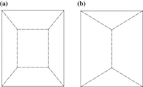
Table 6 shows the applied loading resulting from the blast tests on laminated glass panels considered by Yuan et al. and Del Linz et al. to validate their analytical models. Tests 1–6 presented by Yuan et al. were performed on specimens with thicknesses tG = 3 mm/tPVB = 0.76 mm/tG = 3 mm. Tests 1–3 presented by Del Linz et al. were on specimens with tG = 3 mm/tPVB = 1.52 mm/tG = 3 mm, while Test 4 was on a larger specimen tG = 6 mm/tPVB = 1.52 mm/tG = 6 mm. The applied loading was calculated by multiplying the peak reflected overpressures with the area of the panel. When these are compared to the static collapse load of laminated glass panels (i.e. the ultimate load recorded from the low temperature bending tests shown in Tables 2 and 3) it is evident that the blast loading applied in these tests can be classified as intense loading, as it is well beyond three times the static collapse load.
A direct comparison for specimens with identical thicknesses is made in Table 7 that compares the applied loading derived in Tests 1–3 from Del Linz et al. with the ultimate loading of the CS2 specimens derived from low temperature bending tests by Angelides et al. (2020). Similarly, Table 8 compares Test 4 from Del Linz et al. to the capacity of the CS3 specimens derived by Angelides et al.. Again, it is evident that the applied loading is greater than 3 times the static collapse load. However, the difference in the tests is expected to be less, as a portion of the load was absorbed by the pre-fracture stage and therefore, the applied loading for the post-fracture stage should be less. Additionally, the static collapse load will be higher, as the ultimate loading for the CS2 and CS3 specimens was derived for an idealised pattern.
Table 6 Calculated applied loading for the blast tests used by Yuan et al. (2017) and Del Linz et al. (2018) to validate analytical models - Full size table
Table 7 Comparison of the applied loading calculated for Tests 1–3 presented by Del Linz et al. (2018) with the ultimate loading derived by Angelides et al. (2020) for CS2 specimens (tG = 3 mm/tPVB = 1.52 mm/tG = 3 mm) - Full size table
Table 8 Comparison of the applied loading calculated for Test 4 presented by Del Linz et al. (2018) with the ultimate loading derived by Angelides et al. (2020) for CS3 specimens (tG = 6 mm/tPVB = 1.52 mm/tG = 6 mm) - Full size table
6 Conclusions
This paper has considered the influence of the fracture pattern on the post-fracture bending response of laminated glass with PVB interlayer at the high strain-rates associated with blast loads. Previous, low strain-rate, three-point bending tests performed at low temperature on pre-fractured laminated glass specimens, demonstrated an enhancement of the ultimate load capacity by a factor of two orders of magnitude compared to that at room temperature. The low temperature aimed to simulate the effects of high strain-rate by using the time-temperature dependency of the viscoelastic PVB. In this paper, further low-temperature bending tests have been presented that considered four additional fracture patterns, in order to investigate the influence of the number and size of the glass fragments, the crack alignment and the choice of loading rig.
By comparing the plastic moment capacities recorded from the new tests with those of the idealised fractured pattern recorded previously, it is clear that the moment capacity of laminated glass is unaffected by the number and size of the glass fragments. The moment capacity recorded for specimens with misaligned cracks between the two glass layers has been recorded as almost twice that of specimens with aligned cracks. This higher capacity is attributed to the contribution of the unfractured glass section to the resultant moment. It is therefore concluded that an idealised pattern with aligned cracks results in a lower-bound estimate of the moment capacity for panels with random fracture patterns formed under blast loading, where it is unlikely that all the cracks will be aligned.
A good consistency was observed between the plastic moment capacities resulting from the three- and four-point bending test rigs. This established that both loading rigs produce reliable results, and there is no significant experimental error induced by the three-point rig, in which the point of application of the load coincides with a pre-fractured crack. Additionally, the four-point bending tests have reproduced the significant enhancement of the ultimate load capacity at low temperature, compared to that at room temperature, as observed previously from the three-point bending tests. These tests also demonstrated a fundamentally different failure mechanism at low temperature, and therefore also expected at high strain-rates, in which crushed glass fragments were visible in the vicinity of the plastic hinge. In contrast, no crushing of the glass fragments, even at large deflections, was observed during the room temperature tests, and it is therefore concluded that plastic hinges do not form at low strain-rates.
In summary, these experimental results provide valuable insight into the links between the behaviour of laminated glass observed in small-scale tests and that observed under full-scale blast loading. The results demonstrate that the post-fracture bending moment capacity of laminated glass panels under blast loading can be conservatively estimated from simplified analytical beam models based on specimens with an idealised fracture pattern. To determine the overall panel response, further research is required to incorporate the effects of inertia loading, which is the subject of ongoing work.
References
Acknowledgements
The first author gratefully acknowledges the Engineering and Physical Sciences Research Council (EPSRC) for funding this research through the EPSRC Centre for Doctoral Training in Future Infrastructure and Built Environment (FIBE CDT) at the University of Cambridge (EPSRC Grant Reference No. EP/L016095/1). The contribution of the Institution of Civil Engineers, through the ICE Research and Development Enabling Fund, is also gratefully acknowledged, and the authors wish to thank Romvos Glass S.A. for providing pictures of the lamination process.
Author information
Authors and Affiliations
Department of Engineering, University of Cambridge, Cambridge, UK - S. C. Angelides & J. P. Talbot
Faculty of Architecture and the Built Environment, Delft University of Technology, Delft, The Netherlands - M. Overend
Corresponding author
Correspondence to S. C. Angelides.
Ethics declarations
Conflict of interest
On behalf of all authors, the corresponding author states that there is no conflict of interest.
Additional information
Publisher's Note
Springer Nature remains neutral with regard to jurisdictional claims in published maps and institutional affiliations.


