Article Information
- Digital Object Identifier (DOI): 10.47982/cgc.9. 474
- Published by Challenging Glass, on behalf of the author(s), at Stichting OpenAccess.
- Published as part of the peer-reviewed Challenging Glass Conference Proceedings, Volume 9, June 2024, 10.47982/cgc.9
- Editors: Christian Louter, Freek Bos & Jan Belis
- This work is licensed under a Creative Commons Attribution 4.0 International (CC BY 4.0) license.
- Copyright © 2024 with the author(s)
Authors:
- Michele Andaloro - Werner Sobek
- Enrica Oliva - Werner Sobek
- Lucio Blandini - Werner Sobek
Abstract
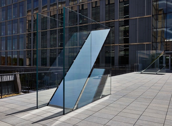
At the core of facade design is the concept of interdisciplinarity, a bridge between concept and materialization apt to relay a built form effectively responding to a wide and diverse spectrum of parameters and aspirations. This paper presents a case study where a facade design approach has been successfully applied to the design and development of a highly complex artwork constituted of structural glass elements. C-010106 by Sarah Oppenheimer—commissioned by the University of Texas’ public art program, Landmarks—is comprised of two structural glass systems acting like periscopes to generate novel views and perspectives from both above and below the footbridge where it is installed.
1.Introduction
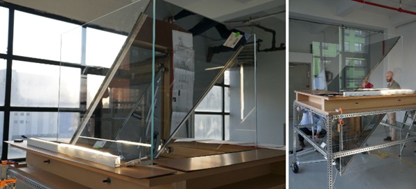
Along with the fabricator and the artist studio, Werner Sobek provided material and component research, development of the design and construction documentation, full engineering of the glass artwork, and oversaw the assembly and the installation of the artwork.
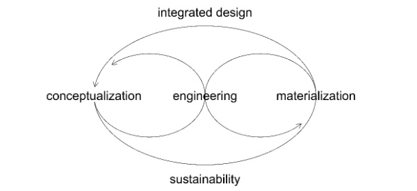
The nature of the artwork—including structural glass designs, advanced concealed titanium and stainless steel fittings and anchors—shared a lot of commonalities with the design process of specialty glazed enclosures where the integration and cross-pollination between design and fabrication is crucial for the successful delivery of a project.
2. Artist’s intent
As described in the essay by Lumi Tan, senior curator at The Kitchen in New York, commissioned by Landmarks at The University of Texas in Austin:
“New York–based artist Sarah Oppenheimer creates works of art that alter the built environment and shift our frame of spatial reference. Pushing the boundaries between sculpture and architecture, Oppenheimer questions the limits of both mediums, upending our experience of inside and out, and inverting our sense of what is near and far. By reorienting the spaces we inhabit, the artist sets out to reconfigure the way we see and are seen.”
“Oppenheimer operates within the disciplines of mechanical, structural, and behavioural engineering. The artist’s relationship to these fields makes C-010106ideally situated between two buildings at the Cockrell School of Engineering.”
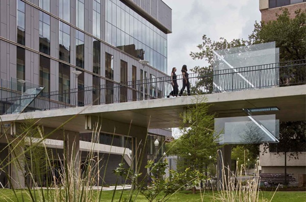
“Located on the pedestrian bridge between the Engineering Education and Research Center and the Energy Engineering Building, the floor-to-ceiling glass features prominently as a way to showcase students at work and to promote multidisciplinary collaboration through formal demonstrations of transparency and access. While C-010106 also uses glass as a material, its function shifts significantly.”
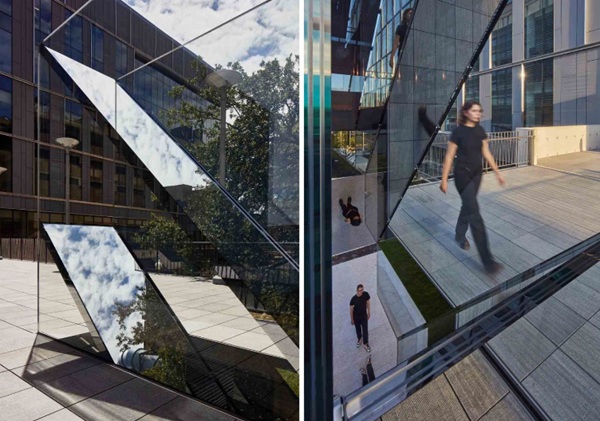
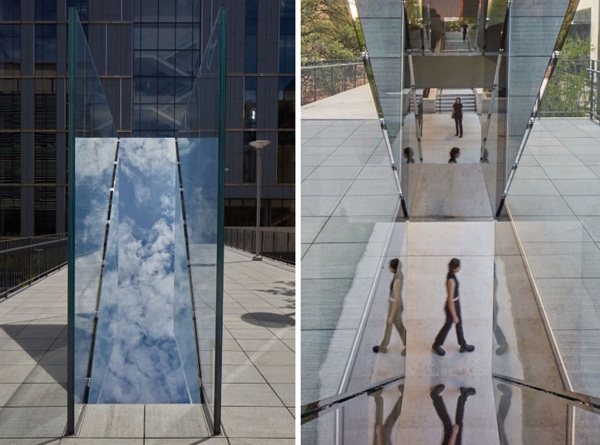
“C-010106 consists of two apparatus at opposite ends of a pedestrian bridge. At each location, a pair of diagonal reflective glass plates are buttressed between a pair of clear glass sheets. At the intersection of the four panes, the glass passes through an incision in the bridge surface, making the apparatus visible both to those above the bridge as well as to those below it. The reflective surfaces within the incision create a surprising effect—permitting pedestrians on top of the bridge to see the reflections of those underneath and vice versa.”
“The bridge serves as a connector between spaces and people. Its utility is clear; it makes travel from one building to another more efficient and direct. Into this transitional space intended for movement Oppenheimer invites new behavioural functions such as observation, contemplation, and social exchange. By siting one apparatus on a north/south axis and another on an east/west axis, a “switch” is created in the flow of traffic and the habitual patterns of movement. The viewer is not limited to a frontal confrontation with the object but is able to engage through it. As the artist remarks, this act of transition is processional, rather than manual in the way one might open or close a door. C-010106 encourages a choreography between people as well as with the shifting light, sound, seasons, and greater environmental rhythms that are in constant flux.”
3. Engineering approach
From an engineering perspective, the main challenge was to develop a structural system that would allow a full expression of the optical behaviour and surface characteristics of the glass without any disruptions created by visible connections or components. The engineering has been carried out simultaneously from two angles: from the outside-in, to analyse the overall stability concept and installation sequence, and from the inside-out, with regards to the details and how they would be integrated in the overall geometry. This process organically merged the Artist’s intent with engineering and manufacturing considerations.
The multiscale approach is very much in line with an advanced facade design approach, where detail-related aspects and building/environmental-related parameters are interwoven in the development of project-specific solutions, and is particularly apt to integrate manufacturing and installation considerations from the early phases of a project.
4. Structural system
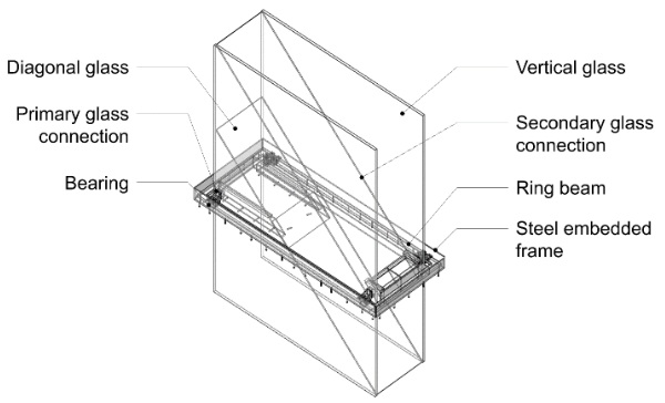
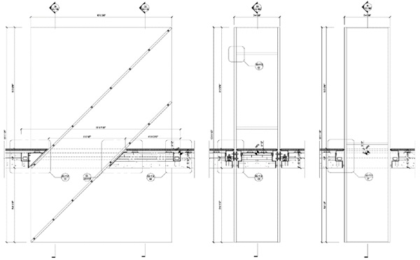
The sculpture—an assembly of two apparatuses measuring 485 x 315 x 86 cm and 142 x 315 x 85 cm—is a structural glass system consisting of seven key components, all contributing to the overall structural stability.
The components can be described as follows:
- An embed frame cast into the concrete bridge deck.
- A steel ring beam supported on four points of the frame by bearing pads.
- The bearings allow for decoupling of the sculptures from the bridge structure, so that movements in the bridge do not induce forces into the sculpture.
- The ring beam distributes the forces applied to the sculpture back into the bearing points.
- The vertical glass panels are connected to the ring beam via stainless steel brackets.
- The diagonal glass is connected to the vertical glass panels through embedded titanium inserts.
4.1. Steel embedded frame
The steel embedded frame consists of hot-dip galvanized, welded, 6mm thick steel plates. The frame acts as a pour stop for the opening in the slab, creating a step-down edge condition on which to support bearing connections. The frame is tied into the concrete slab through welded 12mm-diameter shear studs.
4.2. Bearings
The bearings (type Conslide CSA) connect the ring beam to the steel embed frame. 20mm steel treaded shear studs are welded to the embedded frame assembly. The releases on the four bearings allow for movements in the connections.
4.3. Ring beam
The ring beam consists of 100mm x 75mm x 6mm continuous box profiles, in a rectangular configuration. The ring beam ties the glass sculpture together and allows it to act relatively structurally independent from the bridge base structure. The ring beam also resolves torsional forces resulting from the bracket eccentricities.
4.4. Primary glass connections
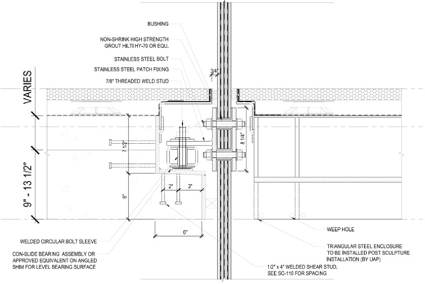
Welded stainless steel plate connection brackets straddle the bearing points along the steel ring beam. These brackets are connected back to the ring beam using blind bolts, and to the glass through stainless steel bolts. The oversized glass hole is grouted with Hilti HIT-HY 70 Grout. The contact surface between glass and stainless steel bracket is achieved with the Hilti Grout layer.
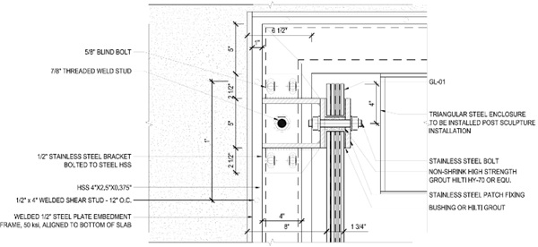
4.5. Vertical glass
The vertical glass consists of 3150mm tall panels, either 1420mm or 4850mm wide. Four layers of heat-strengthened 10-mm thick glass are laminated together with Ionoplast interlayer. Holes in the glass accommodate the base through-bolt connections. Several titanium embeds are located at 600mm spacing to coincide with the edge of the diagonal glass locations.
4.6. Secondary glass connections
Cylindrical Titanium inserts are laminated into the vertical glass at two-foot intervals along the length of the diagonal glass edge. Titanium inserts are also laminated into the diagonal glass and mate with the vertical glass inserts to form the connections.
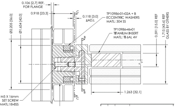
4.7. Diagonal glass
The diagonal glass consists of 850mm wide panels. Three layers of heat-strengthened 8mm thick glass and one layer of fully tempered 15mm thick glass—in correspondence of the laminated titanium insert—are laminated together with Ionoplast interlayer. The 15mm glass layer is notched locally to accept the milled titanium connection insert.
5. Analyses and technical solutions
From an engineering perspective, two aspects were particularly interesting about this project: the development of the overall stability scheme of the sculpture—with the influence of the bridge structure—and the analysis of the structural glass with regards to its global behaviour and the local interaction with the fittings.
5.1. Overall stability concept
A key aspect of the sculpture's engineering design was the analysis of the stability scheme in the final stage and in the transient phases during installation.
The analysis has been carried out in Sofistik, using the assumptions described below. Various load patterns—resulting from Dead, Live, Wind, Snow, Earthquake, Temperature loads and superstructure movements—are used in combinations to attempt to capture the worst-case loading under any condition, including transient phases during installation when the assembly is not complete, and the structural scheme is partial.
The finite element analysis used the non-linear solver which considers non-linear materials and geometry to allow for effects from compression-only bearing, and drift effects, respectively. Superstructure movements are applied as deformations to the model as a seismic load effect. No concurrence of seismic deflections in orthogonal directions is assumed.
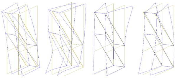
6. Glass design
The structural design of the glass has been carried out through a project-specific workflow, as outlined below, to analyse the global and local behaviour of the glass and to inform the selection and the design of the connections.
Several analysis tools were used to determine the glass build-up for the sculptures. These included:
- Global analysis models in Sofistik
Strength models with full glass thickness
Stiffness models with equivalent glass thickness
- Component models in Mepla
Vertical glazing
-Upper triangle model
-Upper cantilevered glass model
-Isolated vertical without diagonals
Diagonal glazing
- Detail volumetric models in Sofistik
Base connections
Glass-to-glass connections
Stresses are conservatively assumed to be limited to the 3s equivalent allowable edge stresses, for the 1/1000 probability of breakage condition (54.3 MPa).
6.1. Global analysis
Strength models
Overall glass quad stresses and maximum stresses in the diagonal glass are shown below.
![Fig. 12: Maximum quad stress plot [ksi], © Werner Sobek.](/sites/default/files/inline-images/Fig12_173.jpg)
![Fig. 13: Maximum quad stress plot diagonal glazing [ksi], © Werner Sobek.](/sites/default/files/inline-images/Fig13_152.jpg)
Table 1: Overview of the results, © Werner Sobek.

Stiffness model
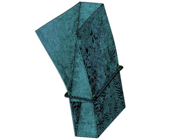
Plate thickness in the Sofistik stiffness models were calibrated to the equivalent Mepla plate models using 600mm by 1200mm cantilever models under unit loads in both pieces of software. A summary of the model deflections under service loads is given below.
Table 2: Overview of the results, © Werner Sobek.

6.2. Component models
Upper triangle model
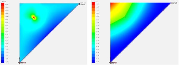
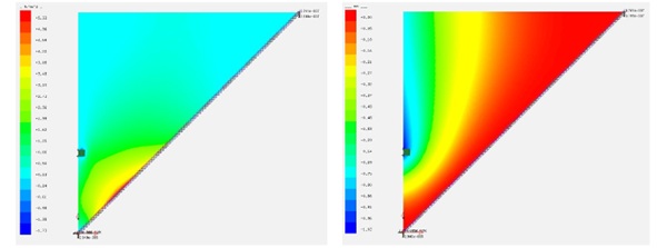
Table 3: Overview of the results, © Werner Sobek.

Impact loading
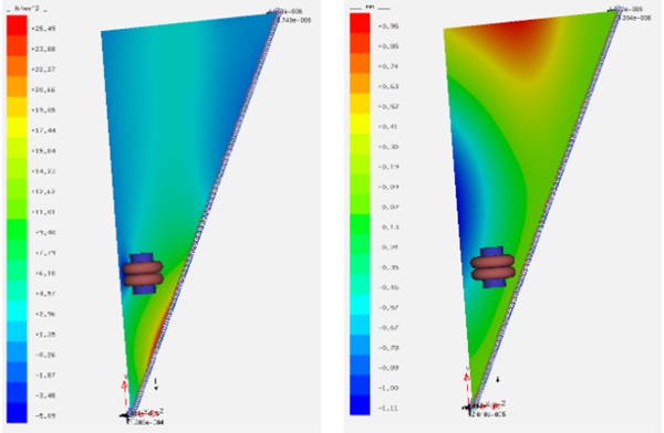
Table 4: Overview of the results, © Werner Sobek.

Upper cantilevered model
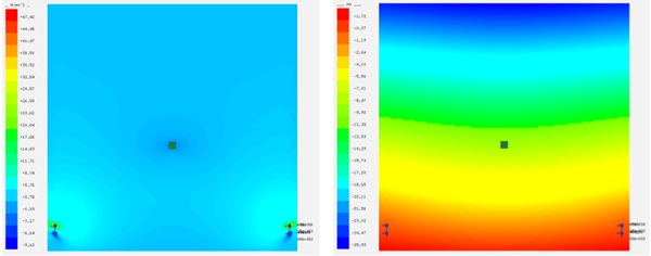
Table 5: Overview of the results, © Werner Sobek.

Full vertical model (unbraced)
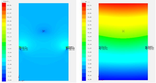
Table 6: Overview of the results, © Werner Sobek.

Diagonal glazing
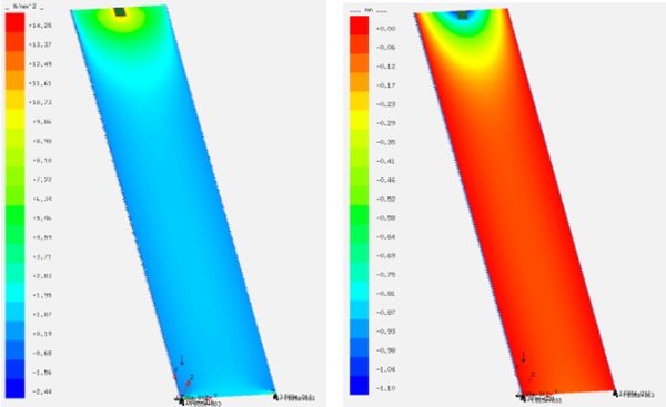
Table 7: Overview of the results, © Werner Sobek.

6.3. Connection detail models
Base connection
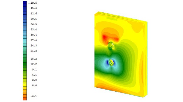
Table 8: Overview of the results, © Werner Sobek.

Glass-glass connection
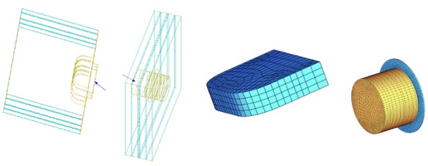
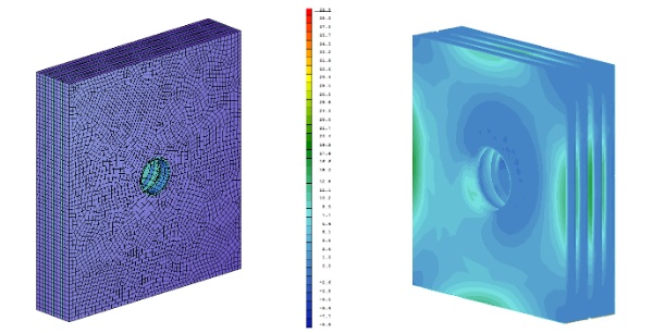
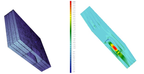
The typical loading on the model is shown above. Equal magnitude loads are applied to the two portions of the model in opposite directions.
Table 9: Overview of the results, © Werner Sobek.

6.4. Fabrication
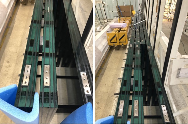
The glass fabrication was performed by sedak (Gersthofen, Germany) that assembled the laminated glass panel with the integrated titanium fittings manufactured by TriPyramid (Westford MA, United States).
The two laminated glass build-ups for the project are composed as follows:
- 4 x 4-ply laminate type A
8 HSG—1.52 SG—15 FT-h —1.52 SG—8 HSG—1.52 SG—8 HSG
ipachrome coating on face 4 and face 7
- 4 x 4-ply laminate type B
10 HSG—1.52 SG—10 HSG—1.52 SG— 2x0.89 SG—10 HSG—1.52 SG—10 HSG
ipachrome coating on face 4 and face 7
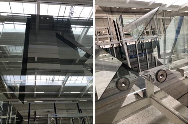
Another interesting aspect related to the design of the glass is the use of the Ipachrome coating by Interpane, a chromium-based multiple-layered coating system, to enable the desired reflection effect and to conceal all visible fittings as well as the base connection to the bridge.
Ultimately, the design of the fittings and the fact that the overall structural assembly relies solely on mechanical connections allow for glass replacement of each panel utilizing temporary supports for stability purposes, similarly to the installation process. Also, in case of breakage, the stability of the system is guaranteed by the residual capacity of the broken laminated glass build-up.
7. Final overview
The interplay between detail development, material properties and overall structural design proved to be crucial for the success of this project, and the general workflow shared numerous aspects with the design process of a specialty facade project—a structural glass facade or a cable-suspended system—where the design of the details is primarily driven by structural considerations, and—conversely—the structural design is heavily influenced by how accurately the behaviour of the system and its details are modelled and captured analytically.
Acknowledgements
The authors wish to acknowledge Sarah Oppenheimer and UAP Company for their contribution to this paper. C-010106was engineered and fabricated in collaboration with UAP Company, sedak, TriPyramid, Thorton Tomasetti, and Arcadia Manufacturing Group.
References
ASTM International: E1300-12a, Standard Practice for Determining Load Resistance of Glass in Buildings, West Conshohocken, PA (2012)
International Code Council, Inc.: 2015 International Building Code, Country Club Hills, IL, USA (2015)
O’Regan, C. (The Institution of Structural Engineers): Structural use of glass in buildings (Second edition), London, UK (2014)
Tan, L.: Essay by Lumi Tan. Landmarks, The University of Texas. https://landmarks.utexas.edu/artwork/c-010106 (2022). Accessed 11 March 2024









Comments
Behavioral, structural, and mechanical engineering are the fields in which Oppenheimer works.