
Article Information
- Digital Object Identifier (DOI): 10.47982/cgc.9. 595
- Published by Challenging Glass, on behalf of the author(s), at Stichting OpenAccess.
- Published as part of the peer-reviewed Challenging Glass Conference Proceedings, Volume 9, June 2024, 10.47982/cgc.9
- Editors: Christian Louter, Freek Bos & Jan Belis
- This work is licensed under a Creative Commons Attribution 4.0 International (CC BY 4.0) license.
- Copyright © 2024 with the author(s)
Author: Mihail Istratii, GLF Facades

Abstract
It has been identified that current standardised method for structural sealant joint dimensioning is applicable to flat rectangular panels only and no provisions are made for panels with curved surfaces. The purpose of this study is to investigate the stress distribution along the sealant joint of a cylindrically curved glass panel subjected to wind pressure and to establish if the panel curvature influences the stress distribution along the joint length. Using the numerical method, several curved units were analysed and the results have shown that the out of plane wind action generates compression and shear forces within the joint, both occurring at the same time. This means that in the case of a structurally bonded curved panel, additionally to the shear caused by differential thermal expansion of elements or glass self-wight which is covered by ETAG 002 and EN 13022 the designer must also consider the shear stress induced due to the panel curvature. The magnitude and location of this additional shear stress and also of the tension/compression stress can be identified using Finite Element Analysis.
1.Introduction
The use of Structural Sealant Glazing system (SSG) in large glass facades is a well-established construction method in current practices (Alcaine et al. 2020). The methodology uses the glass bonding technique to redistribute the applied loads to the façade structure via perimetral structural sealant applied in between the glass infill panel and metallic subframe (ETAG 002 2012). The method originated in 1965 and has been used in projects around the world that have performed well for more than 40 years (Clift et al. 2015).
The application of structural sealant can be realized on site or in the factory. Site bonding typically is not allowed by the specifiers as the procedure requires to be undertaken in a controlled environment, condition which cannot be provided onsite. The preferable option is factory bonding where an adequate quality control procedure can provide a performant construction element (Klosowski and Wolf 2015).
2. Background
In Europe, the mechanical performance of the SSG joint is determined by following the standardised analytical approach which is regulated by ETAG 002 (Wurm J. 2007), EN 13022 and EN 16759. The joint size is a variable depending on glass size, wind load, sealant strength (Van Lancker B. 2020) and is calculated assuming homogeneous stress distribution across the sealant bite (Descamps and Hayez 2018) rigid supports, uniform load distribution, small deformations and linear material behaviour (Clift et al. 2015; Drass and Kraus 2020).
Despite the continuous improvement of the sealants since the 1970’s and the current availability of high-performance structural adhesives the calculation method did not change since (Van Lancker B. 2020). This is currently challenged by the industry due to conservative assumptions used in stress analysis and the high global safety factor 𝛾𝑡o𝑡=6 specified by ETAG 002 (Drass and Kraus 2020). Recent studies propose the dimensioning of SSG assuming a nonlinear distribution of the stresses across the sealant bite (Clift et al. 2015) and by modelling the joint using hyperplastic material(Alcaine et al. 2020; Clift et al. 2015) or by using a spring model to calculate the deformation of structural joints (Descamps et al. 2020). On the other end (Drass and Kraus 2020) are proposing a new Eurocode-compliant design concept for the sealant joint and determine a lower global partial safety factor 𝛾∗𝑡o𝑡=2.72 based on experimental data and for a specific sealant type.
In the case of cylindrically curved structural sealant glazing none of the design rules from the current standards or guideline are applicable as the dimensioning concept according to ETAG 002 is valid only for rectangular, flat glazing (Heinze et al. 2016). In case the design conditions are out of the standard scopes the analysis of stresses and strains within the sealant is recommended to be assessed with the help of Finite Element Method (Memari et al. 2021), (Clift et al. 2015). However, there is no standardised methodology to run FEA for evaluation of SSG but notwithstanding that the method is widely used within the industry as it allows to predict the local stress distribution within the sealant volume (Descamps et al. 2017).
The ETAG 002 and EN 13022 limits the SSG construction to four main types depending on the glass infill and the arrangement of mechanical restraint devices. In all four instances the glass is bonded to the support frame along the perimeter and the out of plane loadings are always transferred to the support frame via bonded connection (ETAG 002 2012).
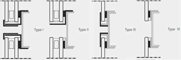
For types I and II only short-term out of plane loads are transferred by the adhesive where for thepermanent in plane loading transfer the use of mechanical self-weight supports is mandatory. The type III and IV are approved for single glazing only as both permanent and variable loadings are allowed to be taken by the structural bond only. In case redundancy is required, the system type I and III have additional mechanical out of plane retaining devices specified which will reduce the danger in case the adhesive fails.
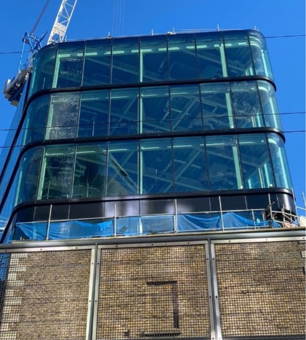
The use of type II SSG in building facades has grown significantly in recent years as it offers a continuous architectural smooth glass surface across the building exterior while providing safety, enhanced thermal, acoustic and blast performance to the building (Alcaine et al. 2020). The use of this SSG type is also observed in the case of facades employing curved glass panels although the design of these is not mentioned and no provisions are made for this panel shape by any standard or guideline.

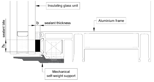
The behaviour of the available adhesives is not fully comprehended and the current standards and guideline limit the design options to a series of rules proven to be adequate over the time (Clift et al. 2015). According to (ETAG 002 2012) the sealant joint should be made of structural silicone only, should be rectangular in cross section and applied continuously along the infill perimeter with the condition that the adhesion is made only on two parallel surfaces.
In a type II flat SSG the sealant bite hc is a variable of the loads acting perpendicular to the glass surface which in turn generate tensile/compression stresses in the structural seal. The maximum stress magnitude is considered to develop at the centre of the longest side of the pane and can be calculated as follows:
![]()
where: a - is the short side dimension of the glass pane, W - is the relevant combined actions of the wind, snow or self-weight and σEd - is the allowable tensile design strength of the sealant.

where: G - is the sealant shear modulus, 𝛥 - is the maximum thermal movement as a combination of elongation along both glass directions and 𝜏Ed - is the allowable shear design strength of the sealant under dynamic loading.
3. Numerical analysis
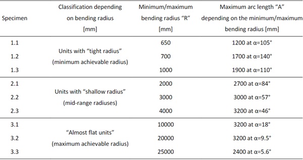
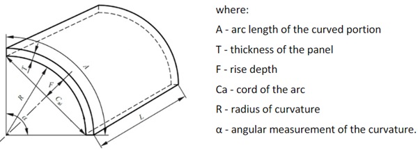
Using linear analysis, a series of type II cylindrically curved structural sealant glazing units are investigated under the action of out of plane wind pressure to analyse the influence of panel curvature on the stress distribution along the joint length. The panels are classified in three categories, “tight”, “shallow” and “almost flat” units depending on the achievable bending angle. Each of the size is referred to the manufacturing capabilities of the glass processors listed in (Timm C and Chase J 2014). The variables presented in table 1 are for 6 mm thick monolithic hot bent tempered glass considering the glass is curved in convex shape, i.e. the curvature radius and performance coating faces the inner side of the building.
Table 1: Curved units specimens.
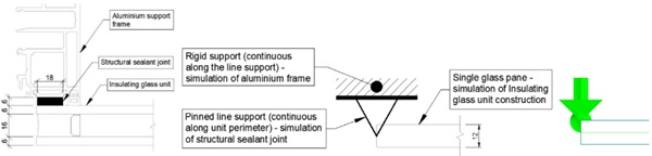
The specimens are modelled by means of geometrically linear finite element analysis using the software package RFEM v.5.27.01 and 2D rigid plate elements. The units are continuously pinned along the perimeter with fixed restraints against any translational displacements along ux, uy, uz and free to rotate around φx, φy, φz. The pressure magnitude considered equals to +/-2.4 kPa which refers to the value used for testing of facade performance mock-ups for safety (CWCT 2006) and which is applied perpendicular to the true area of the unit, upwind.
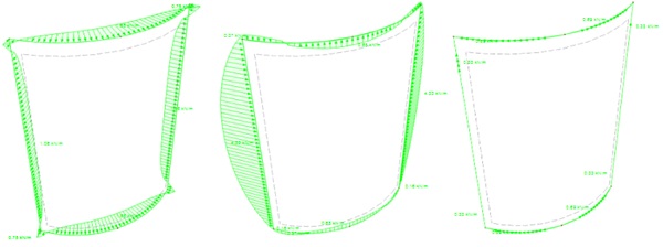
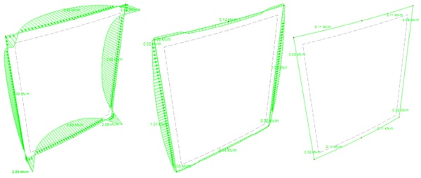
Under the action of out of plane wind loading the line supports exert a linear reaction which is further called “line force” and is used to illustrate the stress distribution pattern and intensity along the structural sealant joint. Using these out of plane line force magnitudes the maximum normal tension/compression stress can be calculated as follows:
![]()
where: σmax - is the maximum tensile stress calculated using maximum out of plane line force magnitude, Rz,max - is the maximum line force magnitude acting perpendicular to the glass plane, hc - is the designed sealant bite.
In the case of other ETAG types the maximum shear stress along the joint can be calculated using in-plane line forces:

where: 𝜏max - is the maximum shear stress calculated using maximum in-plane line force magnitude, Rx,y,max - is the maximum line force magnitude acting in glass plane, b – is the designed sealant thickness.
To validate the Finite Element model, a flat unit is simulated and the results are checked using analytical formulas (1) to (4). The unit measure 4200 mm in height and 3200 mm in width which equals to the arc length of the specimen 3.2 and the goal is to achieve the distribution pattern described in ETAG 002 or EN 13002.
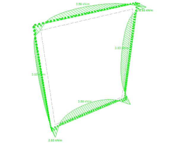
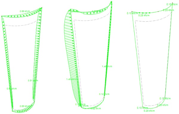
As it can be seen the line force distribution pattern and the maximum magnitude is observed along the longest edge which is like the pattern described in ETAG 002 and EN 13022. Following the same conditions, the specimens presented in table 1 were modelled and the line force magnitude results are summarised in table 2. For illustrative and proof purposes, the line forces for three out of nine specimens/models are presented further.
4. Findings
In the case of curved panels, it can be observed that the distribution of line forces along the perimeter are different than in the case of flat panel. The ETAG type II flat panel subjected to wind pressure generates only line forces along the local z axis “pz” and no line forces along the local y or x axis are recorded. However, in the case of curved panels the out of plane action of the wind pressure generates not only “pz” response but also in plane line forces along y axis “py” and along x axis “px” indicating that beside the short-term pure tension-compression state in the joint there will be shear forces induced at the same time. The maximum shear stress is dominant in magnitude in the case of “tight” and “shallow” units and occur always at the mid height of the straight edge (sample 2.1) whereas for the “almost flat units” the tension/compression forces prevail in magnitude (sample 3.2).
Table 2: Line forces – Peak magnitude of line forces under the action of positive/negative wind pressure.
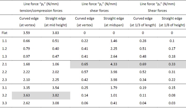
When comparing to the force distribution patterns described in ETAG 002 and EN 13022 the tension compression forces distribution along the joint are qualitatively similar in both flat and curved cases but quantitatively varies in the units with tight and shallow radiuses as the maximum stress is recorded at the centre of the curved sides which is the shortest in this case. Conversely, the shear forces distribution patterns disagree qualitatively as these develop at centres of the curved and straight edges in case of 𝜏y and at 1/3 of the curved edge and the 1/8 of the straight edges in the case of 𝜏x.
The curved units were also analysed separately under the influence of both positive and negative out of plane wind pressure this being applied perpendicular to the true area of the samples, upwind in the first case and downwind in the second and no differences in magnitude or distribution pattern were recorded.
5. Conclusion
Current design rules for structural sealant glazing are related to flat rectangular panels only and no provisions are made for other panel shapes. Following FEM analysis, it was observed that the stress distribution pattern and magnitude along the cylindrically curved structural silicone joint length is different than the stress distribution pattern and magnitude along the flat structural silicone joint. The stress generated by the out of plane loading within the curved structural sealant glazing is multiaxial as the pressure generates not only normal out of plane stresses as in the case of the flat panels but also generates in-plane shear stresses which act simultaneously on the joint. This means that additionally to the shear caused by differential thermal expansion of elements or glass self-wight the designer must also consider the shear stress induced by the panel curvature under the action of wind pressure or any other out of plane loads. As the panel shape deviates from flat the magnitude and location of this additional shear stress and of the tension/compression stress can be identified using Finite Element Analysis.
References
Alcaine, J., Lenk, P., Forwood, E.: Structural Silicone Glazing-Design & Modelling. Challenging Glass 7: Conference on Architectural and Structural Applications of Glass, CGC 2020. (2020). https://doi.org/10.7480/cgc.7.4548
Clift, C., Carbary, L., Hutley, P., Kimberlain, J.: Next generation structural silicone glazing. Journal of Facade Design and Engineering. 2, (2015). https://doi.org/10.7480/jfde.2014.3-4.906
CWCT: Standard for systemised building envelopes. Bath, UK (2006)
Descamps, P., Hayez, V., Chabih, M.: Next generation calculation method for structural silicone joint dimensioning. Glass Structures & Engineering. 2, (2017). https://doi.org/10.1007/s40940-017-0044-7
Descamps, P., Van Wassenhove, G., Hayez, V.: Simulating structural silicone glazing joint deformation with spring models. Glass Structures & Engineering. 5, 171–185 (2020). https://doi.org/10.1007/s40940-019-00105-6
Drass, M., Kraus, M.A.: Dimensioning of silicone adhesive joints: Eurocode-compliant, mesh-independent approach using the FEM. Glass Structures & Engineering. 5, 349–369 (2020). https://doi.org/10.1007/s40940-020-00128-4
ETAG 002: Guideline for European Technical Approval for structural sealant glazing kits (SSGK). (2012)
Heinze, L., Baitinger, M., Wolkowicz, C.: Dimensioning of spherical bent insulated glazing units for the Kazakhstan - Pavilion, Expo 2017. Engineered Transparency. 107–118 (2016). https://doi.org/https://doi.org/10.1002/stab.201690181
ISO 11485-1:2011: Glass in building – Curved glass: Terminology and definitions.
Klosowski, J., Wolf, A.T.: Sealants in Construction (2nd ed.). CRC Press, Boca Raton, FL, USA (2015)Van Lancker, B.: Experimental and numerical investigation of two-sided bonded glass-steel façade units, Gent (2020)
Memari, A.M., Simmons, N., Solnosky, R.L.: Developing FEM Procedures for Four-Sided Structural Sealant Glazing Curtain Wall Systems with Reentrant Corners. Buildings. 11, (2021). https://doi.org/10.3390/buildings11120597
Timm C, Chase J: Thermally curved glass for the building envelope. In: Louter, C.B.F.B.J.L.J.-P. (ed.) Challenging Glass 4 & COST Action TU0905 Final Conference. CRC Press, London (2014)
Wurm J.: Glass structures : design and construction of self-supporting skins . Birkhauser Verlag AG, Berlin (2007)


 demonstrator at Glass Technology Live during Glasstec 2024 (© Cas Maertens).")