Authors: Lucrezia Ravasio, Rajnish Kaur Calay and Raymond Riise
Source: Energies 2021, 14(23), 8068; MDPI
DOI: https://doi.org/10.3390/en14238068
(This article belongs to the Special Issue Energy Efficiency Improvements in Buildings to Achieve Climate Goals)
Abstract
This paper evaluates the thermal performance of a triple-glazed glass window filled with a phase-change material (PCM) compared to the performance of a traditional triple-glazed window with air gaps. The chosen PCM was paraffin wax. A mathematical model to simulate heat transfer within the system was presented. A commercially available software, COMSOL Multiphysics, was used to numerically solve the governing equations. The analysis was carried out for the representative days of different seasons using three types of paraffin wax (5, 10, and 15) that have different melting-temperature ranges. Particularly, the study considers the unique climatic conditions of the Arctic region. Results showed that by integrating a PCM into the cavity of triple-glazing, thermal performance during summer season of the window was enhanced, while for spring and autumn thermal performance was affected by the type of paraffin selected. The thermal performance of glass windows during winter did not change with PCM integration.
1. Introduction
The urgent climate change issues due to the intense depletion of natural resource are highlighting, now more than ever before, the need to reduce the impact of human activities on the planet. In particular, the latest 2020 Global Status Report for Buildings and Construction [1] evidenced how the building sector is still severely contributing to global total emissions. Indeed, in 2019 it accounted for 35% of global total emissions, and 38% of energy related carbon dioxide emissions, maintaining the same emission trend as past years. Therefore, it is essential to take action on different levels to minimize the carbon footprint of the whole construction sector, and achieve the ambitious goal of a net-zero emissions society by 2050.
Right now, these strategies mainly involve the decarbonization of power production, through the transition to renewable energy sources, along with reduction of material-lifecycle carbon emissions, by applying a circular economy model. However, these initiatives should also be accompanied by an upgraded building code, market regulations and incentives for the enhanced energy efficiency of buildings. In this regard, cutting global total emissions is a high priority for the Arctic, which is warming three times faster than the rest of the world, where changes have global implications [2]. Moreover, harsh Arctic climate conditions, along with long distances and small communities, represent additional challenges to the decarbonization of the region, due to the significant amount of energy needed for heating buildings and transportation [3].
Therefore, local energy production and storage will be one of the biggest technological challenges of the upcoming decades. In particular, latent-heat thermal energy storage (LHTES) based technologies have been under investigation for years. By storing and releasing latent heat, these systems improve the thermal performance of buildings and reduce on-peak electricity demand [4]. Moreover, LHTES technologies provide a high energy-storage density per unit of mass, at near-constant temperatures, compared to other thermal energy storage (TES) solutions [5]. Phase-change materials (PCMs) are used as LHTES technologies inside building components, and their application ranges from active to passive heating and cooling systems, including integration into glazed surfaces. In fact, since windows represent, in cold climates, the weakest barrier of a building—accounting for about 10–25% of the total heat loss through the building envelope [6]—PCMs represent an opportunity to enhance their thermal inertia, while preserving the transparency when in liquid phase and diffusing the light when in solid state [7].
Despite the numerous studies on PCM integration in transparent building components that can be found in literature, only a few focus on their application in cold-climate environments. A study reviewing the available literature on the topic, published between 1997 and 2018 [8], shows that only 37% of existing studies were performed in cold climate conditions. Among these, only two were carried out under southern-Norway climate conditions, and none under Arctic climate conditions. Goia F. et al. conducted several studies on PCM applications in transparent building components in Norway. In 2012, the author developed a numerical model for investigating the thermal performance of a simple PCM glazing system—composed of two glass and one PCM layer—during different seasons, and later validated it by experimental analysis [9,10].
Results from these studies showed that PCM glazing systems were able to improve thermal condition of indoor environment for most of the time, during various seasons. However, in days with low-incident solar radiation, their performance was similar to that of a standard glazed window. Shuhong Li et al. conducted similar research in 2014 [11]. The study investigated the effects of a phase-change-material-filled glass window on building energy consumption in hot-summer and cold-winter areas of China. Results still showed a technology performance to be satisfactory on sunny summer days, while unsatisfactory in rainy winter days, as it could not decrease energy consumption. In 2017, Bianco L. et al. proposed a more complex system [12], composed of a triple-glazed unit with a PCM-filled cavity and thermotropic glass placed on the outer side, for regulating the phase transition of the PCM layer.
In particular, the study aimed to test different configurations of the glazing system under winter conditions in Turin (Italy), which is characterized by a humid subtropical climate. The proposed system solved some criticalities, highlighted in previous studies [10,13], related to the decrease of overall thermal resistance during the cold season—and showed a promising range of dynamicity during sunny winter days. A similar system was also investigated by Changyu et al. in 2018 [14]. The study proposed a simplified calculation method—validated by experimental results—for the analysis of the thermal performance of a system consisting of a PCM layer and four glass layers. Different PCM thicknesses were evaluated, and the results highlighted that PCM thickness plays a significant role on the thermal performance and solar transmittance of a multilayer glazing façade.
In fact, increased PCM thickness increases interior surface temperature and temperature time lag. In order to improve the optical performance of PCM windows, Dong Li et al. examined a double-glazed window with dispersed nanoparticles inside the PCM layer [15]. Research outcomes revealed that nanoparticle-integrated systems have better thermal and optical performance than pure-paraffin systems. In a later study [16], the same authors examined the effects of nanoparticle volume fraction and particle diameter on the interior glass-surface temperature, for representative days of different seasons in Daqing City, which is characterized by a humid continental climate. Moreover, they also developed a triple-glazed window where the air layer was replaced by silica aerogel, in order to improve insulation [17].
The aim of the research was to investigate to what extent the thermal and physical properties—like density, specific heat, thermal conductivity, and thickness—of silica aerogel can affect the thermal performance of windows in cold environments. Finally, in 2021, Shu Zhang et al. numerically examined and compared the energy performance of ten different window configurations under the severe cold climate of China [5]. The study included double- and triple-glass layered windows, integrated with silica aerogel and/or PCM. Results highlighted that, generally, adding PCM to glass windows induces the necessity of also adding an external insulation layer, to ensure the charging and discharging of the working circle of the layer.
Based on these premises, the present paper aims to numerically investigate the energy performance of a triple-glazed window integrated with PCM under Arctic climate conditions. There is little available literature on the applicability of this technology in cold climates. Thus, this work would be the first of its kind to carry out a preliminary study in the Arctic. The region is unique, being characterized by very low solar radiation during the winter and autumn months, and by large solar-resource availability during the spring and summer months. In this regard, due to the low average air temperature also present during bright months [18], this technology could be used for heating purpose during the whole year. Moreover, in the context of building renovation, a PCM-filled window could represent an opportunity to easily enhance buildings’ performance, and achieve new building standards and certifications, without radical action on the whole-building structure.
This study adapted a numerical model [9] of the climate characteristics of Northern Norway, and simulated the case studies presented in this paper. The commercial software COMSOL Multiphysics was used for simulations. The case studies consisted of one characteristic day for each season and three PCMs with different melting points. The performance of the PCM-filled window was compared to a standard triple-glazed widow filled with air.
2. Materials and Methods
2.1. Model Description
2.1.1. Physical Model
The schematic physical model of the triple-glazed window is presented in Figure 1a.
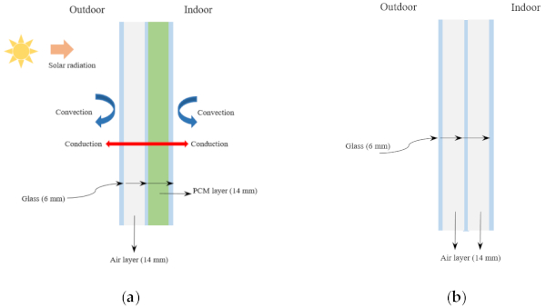
The unit was composed of three glass layers of 6 mm each, and two cavities of 14 mm each, filled with air and macro-encapsulated PCM, respectively. The air layer provided thermal insulation due to its low thermal conductivity, while the PCM layer acted as thermal storage. In fact, during the day, it absorbed part of the incoming solar radiation and changed phase from solid to liquid. Similarly, during the night, the accumulated heat was released into the indoor environment, and the PCM-layer returned to a solid state. Therefore, this endothermic and exothermic based process was useful in reducing building energy demand, while maintaining the comfort of the indoor environment.
The selected PCM for the study was paraffin wax, a material that was, largely, investigated for similar purposes in previous studies [8]. In particular, paraffin 5, paraffin 10, and paraffin 15 were chosen due to their melting temperatures, which were compatible with the outdoor temperature, and their possible activation range. As highlighted in the previous studies presented in the Introduction, the inner cavity of the triple-glazed window, near the interior, was filled with paraffin in order to easily achieve the phase-change cycle.
Similarly, the schematic physical model of the standard triple-glazed window is showed in Figure 1b. It presented the same layer structure and dimensions of the PCM triple-glazed window, with the difference that the second cavity was filled with air instead of paraffin. The thermo-physical properties of the layers are showed in Table 1, where k, ρ, and cp indicate thermal conductivity, density, and specific heat, respectively; cp,s, cp,l, LH, Tm, and dT refer to the PCM’s thermal properties, and indicate specific heat of solid state, specific heat of liquid phase, specific latent heat of fusion, melting point, and phase-change temperature range, respectively.
Table 1. Thermo-physical properties of glass, air, and PCM [16].
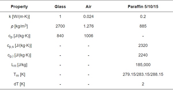
By comparing the results of these two window models, it was possible to obtain a preliminary evaluation of the energy performance of the PCM technology under arctic climate conditions, and discuss how PCMs’ melting temperatures act in different seasons.
2.1.2. Mathematical Model
We used a previously developed and validated model [10,13] to simulate heat transfer within the different layers, i.e., the glass layers, the air layer, and the PCM layer. In this study, we make the following assumptions:
- One-dimensional and transient heat transfers perpendicular to the glass surface;
- Convection within the PCM layer is negligible due its small thickness;
- The thermo-physical properties of the glass are isotropic;
- Of the thermo-physical properties of the PCM, conduction and density are temperature independent, while specific heat is temperature dependent;
- The radiative heat exchange between the glass surfaces facing the PCM layer is neglected;
- Volume expansion during the phase change, and the scattering effects of the paraffin, are ignored.
We can write the Fourier equation to describe the conduction heat transfer in the three glass panes as follows:

where 𝑇𝑔 is the temperature (K) of the glass; 𝜌𝑔, 𝑐𝑝,𝑔, and 𝑘𝑔 represent, respectively, the density (kg/m3), specific heat (J/(kg∙K)) and thermal conductivity (W/(m∙K)) of the layer; 𝑞˙𝑠𝑜𝑙 is the solar heat source (W/m2), and τ is the time (s).
For the conduction and radiation heat-transfer processes within the PCM layer, the equation is written as a rate of change in enthalpy (Equation (2)):

where ρpcm and kpcm are the density (kg/m3) and thermal conductivity (W/(m∙K)) of the PCM layer, respectively. The specific enthalpy of the PCM is given by Equation (3):
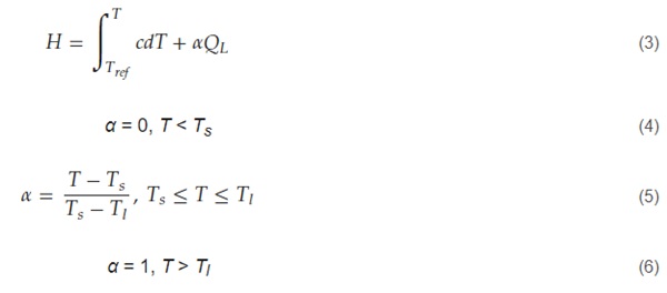
where c and QL are the specific heat (J/(kg∙K)) and latent heat (J/kg) of the PCM, respectively; α represents the liquid fraction of PCM undergoing phase change, while Tref, Ts, and Tl are, respectively, the reference temperature, solidus temperature and liquidus temperature of the layer.
Boundary conditions on the exterior surface of the outer glass and on the interior surface of the internal glass were described by (7) and (15).
The exterior surface of the outer glass was exposed to solar radiation; hence the boundary condition was defined as Equation (7):

where hout, 𝑇𝑒𝑔,𝑜, and Ta,o represent the convective heat transfer coefficient (W/(m2∙K)) of the outer environment, outer surface temperature, and outdoor air temperature (K); hout was calculated with the following equation (Equation (8)) considering the wind speed v [9].
![]()
The total radiative flux from the outer surface to the external environment (W/m2) was represented by 𝑞˙𝑟𝑎𝑑, defined as Equation (9):
![]()
where 𝑞˙𝑟𝑎𝑑,𝑎𝑖𝑟 and 𝑞˙𝑟𝑎𝑑,𝑠𝑘𝑦 are the radiative heat transfer (W/m2) from the glass surface to the atmosphere and to the sky, respectively (Equations (10) and (11)).

where σ is the Stefan-Boltzmann constant, εs,o is the emissivity of the glass surface facing the outdoor environment, and Fsky is the view factor between the vertical façade and the surroundings. β is a coefficient that divides the heat exchange with the sky dome between sky and air radiation. Fsky and β are both function of δ, which is defined as the angle between the vertical façade and the ground. These coefficients were calculated as follow (Equation (12)).

Finally, Tsky is a function of outdoor temperature Ta,o, and it is defined as Equation (14):
![]()
The interior surface of the inner glass is facing the indoor environment; hence, the following boundary condition applies (Equation (15)):

where hin, 𝑇𝑒𝑔,𝑖, and Ta,i represent the convective heat transfer coefficient (W/(m2∙K)) of the indoor environment, inner surface temperature, and indoor ambient temperature (K). Since it is supposed that only natural convection occurs within the room, hin can be determined using the following equation (Equation (16)) [19].

where ΔT is the temperature difference between the inner glazing surface and the indoor air. H is the façade height.
Finally, the boundary condition at the interfaces between different media in the glazing system was given by Equation (17):

2.2. Numerical Methods and Validation
The model of this study was built using COMSOL Multiphysics. The governing equations were discretized by the software using a finite element method, and iteratively solved by implicit scheme, with second order accuracy. Even if this numerical model was validated in previous studies, simulation results were compared with those from previously published literature [5,17].
However, since this study aimed to premilinarily investigate the feasibility of the application of the window in the Arctic, the model was simplified. Indeed, the three glass panes were approximated as transparent surfaces, while the PCM layer was treated as an opaque surface. In fact, evaluation of optical properties of the PCM layer will be the object of following comprehensive studies, as well as experimental analysis.
2.3. Environmental Conditions
Narvik, Norway, was chosen as the location of the study. It is a small town located 220 km inside the Arctic Circle, and—according to Köppen Climate Classification—it presents a humid continental climate. Due to its position in the Arctic region, this town is characterized by long, dark winters and autumns, and very bright springs and summers.
The window was located on a vertical surface facing south. As the analysis considered one characteristic day for each season, Figure 2a illustrates the air temperature data for the selected days. Likewise, Figure 2b shows the solar radiation for the same days. For the analysis, daily equivalent sun hours were used. This method approximates the solar radiation daily trend, with the number of hours per day during which the average solar irradiance was 1000 watts per square meter [W/m2] at the selected site. The data source was the National Renewable Energy Laboratory (NREL). By running simulations in different seasons, it was possible to obtain results for a wider range of outdoor temperature, wind speed, and solar radiation conditions.
![Figure 2. Meteorological data. (a) Outdoor air temperature for four characteristic days of four different seasons in Narvik [20]. (b) Equivalent solar radiation for four characteristic days of four different seasons in Narvik [21].](/sites/default/files/inline-images/Fig2_397.jpg)
2.4. Simulation Parameters
Initial and boundary conditions were set before running simulations. As a boundary condition, the air temperature of the indoor environemnt—shown in Figure 3a—was set to 22 °C from 8:00 to 21:00, and to 0 °C for the rest of the day. In this way, it was possible to simulate the presence of a heating system. The initial temperature was set to the same temperature of the indoor environment at time zero. Figure 3b shows the outdoor heat-transfer coefficient, calculated with Equation (8), and meteorological data on wind speed. Indoor surface heat-transfer coefficients were also calculated using Equation (16), as previously introduced. The simulation time was 48 h—hence the air temperature and solar radiation data of the first day were repeated for the following day—in order have a better view of the charging and discharging process of the PCM layer. The step time was set at 2 s.
![Figure 3. (a) Indoor air temperature. (b) Outdoor heat transfer coefficient for four characteristic days of four different seasons in Narvik [20].](/sites/default/files/inline-images/Fig3_379.jpg)
3. Results and Discussion
3.1. Calculated Parameters
The developed model—already validated in previous studies – was used to evaluate the performance of PCM in reducing temperature fluctuations on the inner surface of the proposed system, and, hence, increase thermal comfort of the indoor environment. The analysis considered different seasons and three types of paraffin, characterized by different melting temperatures. Thus, to assess the thermal performance of the PCM-filled window, the following parameters were investigated and compared with results from a standard glazed window:
- Inner surface temperature;
- Liquid phase rate of the PCM;
- Heat flux through the inner surface.
3.2. Paraffin 5
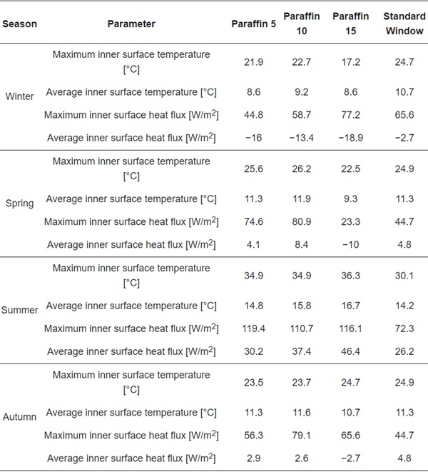
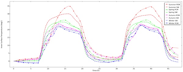
The temperature trends of the inner surface of the paraffin 5-integrated window and standard window, for different seasons, are presented in Figure 4. Looking at simulation results, it can be found that, in the selected time span, the insulation performance—which was represented by the inner surface temperature—varied with the season. For instance, during winter the standard window showed better insulation performance than the PCM-filled window, with an average inner surface temperature of 8.6 °C, compared to 10.7 °C, as showed in Table 2.
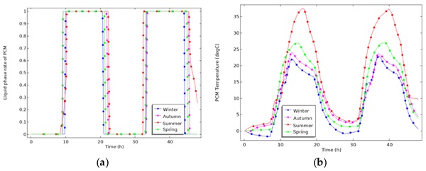
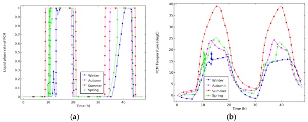
The temperature trend for the two window configurations was similar during spring and autumn, with an average inner surface temperature of 11.3 °C, as shown in the same table. Instead, results of the summer case show better insulation performance from 14:00 of day one until 6:00 of day two, due to higher outdoor temperatures and longer solar radiation, which kept temperatures higher than in the standard-window case. From Figure 5a, it can be seen that, in all seasons, the liquid phase ranged from 0 to 1. This indicates that paraffin 5 could perform the phase change cycle throughout the day. However, during summer and autumn the liquid phase period last more than other seasons. The energy storing- and releasing-effect can also be visualized in Figure 4.
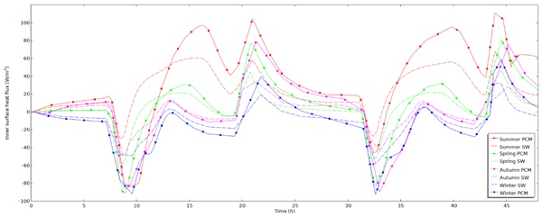
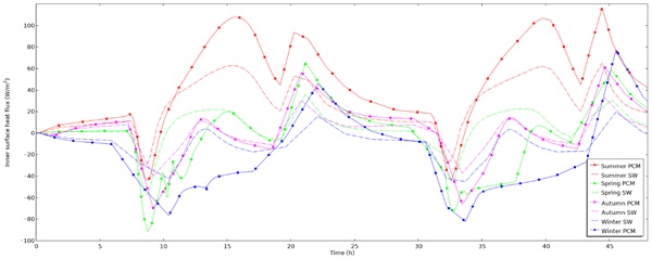
In fact, from 21:00 of day one until 6:00 of day two, the inner surface temperature of PCM window was higher than standard window for all seasons. For instance, looking at the graph of Figure 5a,b, the PCM layer changed phase from liquid to solid, and at the same time its temperature decreased, releasing heat. Table 2 also shows that the average surface-heat fluxes—displayed in Figure 6—were lower in winter and spring for the PCM window than for the standard window, and inversely, higher for the PCM window than the standard window during summer and autumn. The same figure shows that surface-heat-fluxes peaks occurred at 15:00 and 21:00 of both days, concurrently with the not-operation time of the when the heating system (see Figure 3a).
This behavior can be explained by the fact that the absorption of solar radiation by the PCM layer prevents a portion of solar radiation from entering the indoor space. Moreover, thermal energy was dissipated within the indoor space by conduction and radiation.
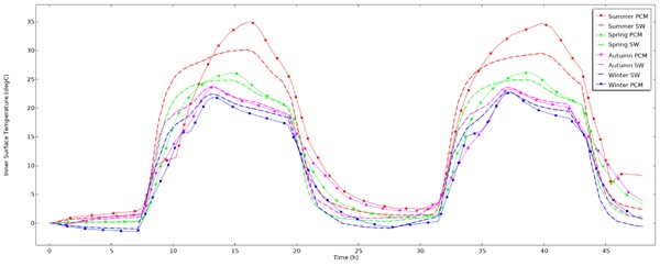
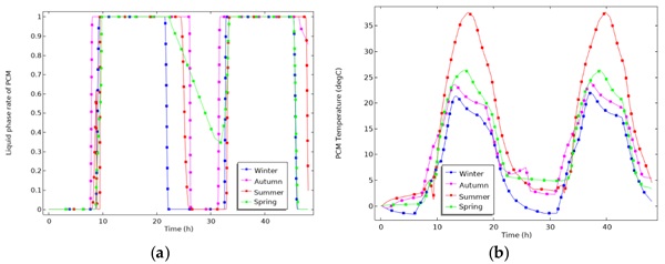
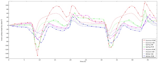
Table 2. Thermal performance parameters of paraffin 15-filled window and standard window and for different seasons.
3.3. Paraffin 10
The temperature trends of the inner surface of the paraffin 10-integrated window and standard window, for different seasons, are presented in Figure 7. As in the paraffin 5 case, the insulation performance of both windows was very similar during winter. Data also show similar behavior to the previous case during spring and autumn, with a slightly higher average inner temperature—respectively of 11.9 °C and 11.6 °C in the PCM window compared to 11.3°C in the standard window (see Table 2). The insulation performance in summer is confirmed greater for the PCM-window than the standard window.
Furthermore, the average and the maximum indoor temperatures resulted higher than the case with paraffin 5 during all the seasons. Compared to paraffin 5 case, heat flux peaks occurred later in the day—around 16:00 and 21:00. From Figure 8a, it can also be seen that, in this configuration, the liquid phase rate of PCM ranges between 0 and 1, so the complete solid-liquid cycle was performed. Moreover, with paraffin 10, the PCM layer presented the same liquid rate duration in all seasons. As for paraffin 5, from 21:00 of day one to 6:00 of the following day, the inner surface temperature of the innovative window was higher than in the standard window, due to the energy charge and discharge effect. This phenomenon can be visualized also in Figure 8a and Figure 9.
3.4. Paraffin 15
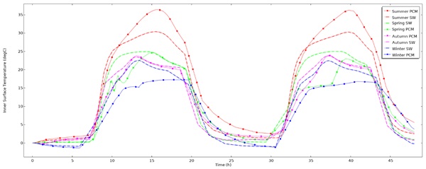
The temperature trends of the inner surface of the paraffin 15-integrated window and standard window, for different seasons, are presented in Figure 10. In this case, results show that during winter the inner surface temperature of the paraffin 15-filled window is equal to 8.6°C as in the paraffin 5 window. This happened because the layer reached the phase-change temperature later than in the other configurations—see Figure 11b, compared to Figure 5b and Figure 8b—and hence kept the inner temperature lower. The liquid phase rate graph (Figure 11a) highlights also that, during winter, the PCM layer stayed in liquid state for less time than in the other cases.
Furthermore, during autumn and spring, thermal performance was scarcer than in paraffin 5 and paraffin 10 cases (see values in Table 2), as result that the phase-change temperature was reached later. This has also led to lower insulation performance, and, hence, more heat consumption to keep the indoor temperature high. Summer was the season with the most benefits from paraffin 15. For instance, result showed higher average and maximum inner surface temperature, respectively, of 16.7 °C and 36.3 °C, than previous cases. Looking at the graph of heat fluxes in Figure 12, it is possible to see that peaks still happened around 15:00 and 21:00.
4. Conclusions
In the extreme cold conditions of in the Arctic region, the amount of energy required to maintain a comfortable indoor environment is significant. This paper investigated using PCMs within the cavity of triple-glazed windows in order to reduce heat loss through windows, thereby reducing the overall energy consumption of heating a building. The comparison was made between a standard triple-glazed window and PCM-filled triple-glazed window. The analysis aimed to assess the thermal performance of this type of LHTES technology under Arctic climate conditions.
After building the mathematical model, the equations were solved using the software COMSOL Multiphysics. Three different types of paraffin were evaluated considering a characteristic day for each season. Based on numerical analysis following conclusions can be made:
- During summer, the PCM-filled window had better thermal performance—measured as inner surface temperature and thermal insulation—compared to a standard window. This was because summer is characterized by higher outdoor temperatures and more availability of solar resource than other seasons.
- During spring and autumn, paraffin 10 performed better than paraffin 5 and paraffin 15, resulting in higher average and maximum inner surface temperature. Indeed, with paraffin 10 the PCM layer stayed in a liquid phase for longer time compared to other cases, hence leading to better performance.
- During winter season, no benefit was observed for a PCM-filled window. The energy efficiency of the PCM-filled cavity was either worse than, or at best similar to, the efficiency of a standard window. This was because of the extremely low outdoor temperatures and the lack of solar radiation.
Finally, the results indicate that paraffin 10 could be the best solution among the investigated PCMs, because it provides the best window performance during spring and autumn—which are season characterized by low outdoor temperatures—and second-best performance in summer. On the other hand, this technology provides no benefits during winter. Finally, the study suggests more investigations to evaluate the optical properties of phase-change materials, and their effect on visual indoor comfort.
Author Contributions
Conceptualization, L.R., R.R., and R.K.C.; methodology, L.R., R.R., and R.K.C.; software, L.R.; validation, L.R.; formal analysis, L.R.; investigation, L.R.; resources, L.R.; data curation, L.R.; writing—original draft preparation, L.R., R.R., and R.K.C.; writing—review and editing, L.R., R.R., and R.K.C.; supervision, R.R. and R.K.C. All authors have read and agreed to the published version of the manuscript.
Funding
This research received no external funding.
Data Availability Statement
Data available at Dataverse.no.
Conflicts of Interest
The authors declare no conflict of interest.


