Article Information
- Digital Object Identifier (DOI): 10.47982/cgc.9.583
- Published by Challenging Glass, on behalf of the author(s), at Stichting OpenAccess.
- Published as part of the peer-reviewed Challenging Glass Conference Proceedings, Volume 9, June 2024, 10.47982/cgc.9
- Editors: Christian Louter, Freek Bos & Jan Belis
- This work is licensed under a Creative Commons Attribution 4.0 International (CC BY 4.0) license.
- Copyright © 2024 with the author(s)9
Authors:
- Michael Stern - Evenline Inc., USA
- Ethan Townsenda - Evenline Inc., USA
- Daniel Massimino - Massachusetts Institute of Technology, USA
- Kaitlyn Becker - Massachusetts Institute of Technology, USA

Abstract
This study investigates the feasibility of 3D printing with recycled glasses, focusing on comparing viscosity characteristics and extrusion behaviors of studio soda-lime glass, recycled soda-lime container glass, and recycled float produced window glass. Employing multiple methodologies, we analyzed the temperature-viscosity curves of these glass types, providing an understanding of their thermal properties in relation to 3D printing process and applications. We employed infrared (IR) thermography to calibrate the glass printer and gain insights into the characteristics of each glass type during extrusion, contributing to a deeper understanding of their printing behavior. We discuss the potential applications of this work in various fields, such as recycled glass architecture and mass product customization. This study contextualizes the use of different glass sources for 3D printing and discusses some of the manufacturing challenges of utilizing post-consumer recycled glass. Our findings open new avenues for customized fabrication with recycled materials, paving the way for innovative and sustainable practices with a larger library of materials for 3D printing technology.
1.Introduction
1.1. Recycled Glass
Glass can be recycled with little to no degradation to its performance and remelting glass consumes less energy than melting virgin material (Tooley 1984). The large quantity of post consumer glass waste is a potentially valuable source of material. Furthermore, its typical pathway to either downcycling or landfill highlights an implicit challenge for society of how to reuse recycled glass instead (Dhir 2001). As with plastics, concrete, and metals, glass 3D printing allows for the direct fabrication of a near net shape or finished object without material waste associated with subtractive manufacturing. 3D printing also avoids the need for custom tooling or disposable mold materials as required by forming and casting manufacturing techniques (Jordan 2018). 3D printing has the potential to achieve higher material efficiency by enabling the creation of complex hollow structures. Recent research has explored the use of recycled glass in cast masonry blocks (Oikonomopoulou et al. 2020). In this work we build on this recent research on casting recycled glass into structural masonry to demonstrate the feasibility of implementing recycled container and float glass in additive manufacturing. 3D Printed recycled glass can be used for commercial scale manufacturing of home goods, lighting, decorative facades, and structural masonry, expanding the accessible design space of forms while reducing material waste.
1.2. Advances in Glass Additive Manufacturing
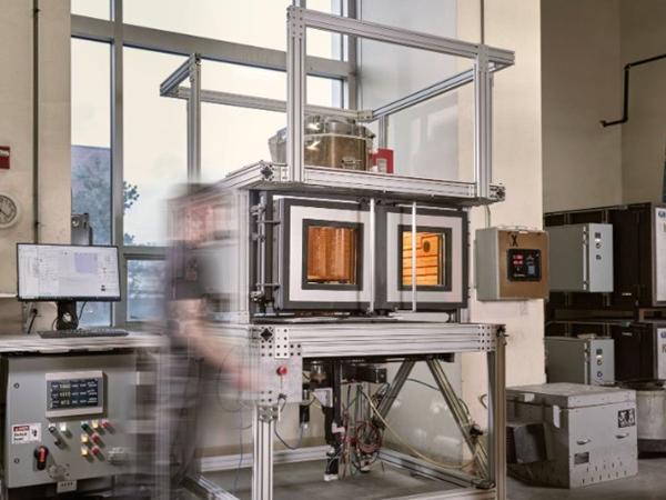
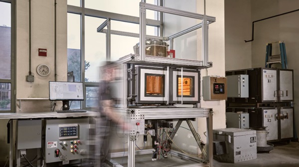
As with all manufacturing technologies, compatibility and process tuning for specific materials is a necessary hurdle to viability. Different glass formulations are tuned to the process for which they are intended, and our research explores the necessary adaptations of the state of the art of glass 3D printing to work with recycled window glass made with the float glass process and bottles as a specific example of container glass. From here on all window glass will be referred to as float glass and all bottle glass as container glass. This exploration focuses specifically on the temperature-viscosity behavior of recycled glass as a primary determinant of the functional requirements and compatibility with existing molten glass additive manufacturing. For example, soda lime container glass has a higher melting temperature and transitions more quickly below the softening point to increase production throughput (Tooley 1984). By contrast, soda lime studio glass used for artisanal glassblowing and previous demonstrations of glass 3D printing (Klein et al. 2015) is formulated for a lower working temperature and is described as ‘longer’ glass, meaning that it has a longer working time before it cools to below the softening point. To adapt to a larger array of glass formulations, the most recent glass printer developed by Evenline Inc., the Glass 3D Printer 3 (G3DP3), has been upgraded from its predecessor G3DP2 (Inamura et al. 2018) to ready the technology for commercial use. The upgrades made to G3DP3 for printing with recycled float and container glass include the incorporation of infrared (IR) temperature monitoring, larger build volume, redesigned nozzle, higher temperature operation, and enhanced tool pathing capabilities and prediction. Evenline currently uses the G3DP3 technology for internal production of both art and design objects, to fabricate custom parts for clients and to conduct research with partnering organizations.
1.3. Additive Manufacturing with Recycled Glass
In parallel to software and hardware upgrades of G3DP3 for printing recycled glass, this work outlines a process and methodology to understand the flow behavior of glass and account for changes necessary to print with these untested glasses. We characterize the sensitivity of the additive process to glass composition, discussing the material preparation, and introduce a framework for tuning printing parameters to the temperature-viscosity profile of a given glass formulation. This material and process characterization allowed us to demonstrate commercial production of home goods, structural masonry, and sculptural work. These demonstrations consist of objects that are fully printed with recycled glass, as well as a construction hybrid where recycled float glass is printed directly onto a sheet of float glass. By establishing processing parameters for additive manufacturing with recycled glass, and a means of calibrating additive manufacturing across several glass formulations, we expandthe design space for sustainable and circular glass fabrication.
2. Glass Characterization for Printing Calibration
To enable printing of recycled float and container glass, the glass composition was measured and implemented in a model to predict the viscosity-temperature relationship. The float glass characterized in this work was Optifloat from Pilkington, and the container glass, referred to as Sapphire, was sourced from a recycling center in New Orleans. These were compared to four types of studio glass previously tested on the printer, listed in Table 1. Float and container glass are known to have a higher melting temperature than that of soda lime studio glasses, which are formulated for manual glassblowing. From the viscosity-temperature relationship, process parameters were selected for an initial printing calibration. During the printing process, the thermal profile and flow of the glass were monitored with a thermal camera. These were compared to the resulting mass versus the predicted mass of the printed forms to compare the relative extrusion rates. Details of each of the characterization and calibration steps described above are explained in the section below.
2.1. Material Characterizations
A JEOL JXA-8200 Superprobeelectron-probe microanalyzer (EPMA) or Electron Microprobe was used to measure the chemical composition of five different formulations of soda lime glass, the results of which are shown in Table 1. This measurement is limited by its inability to accurately measure elements lighter than Oxygen. Of these, Lithium, Boron, and Oxygen are known to be used in glass formulations to control various properties (Tooley 1984). To avoid discrepancies between the E-Probe results and the actual glass formulation, safety data sheets and product specification sheets were compared to experimental results, and we assumed the addition of Lithium Oxide to the formulation. Following this process, we normalized the adjusted total experimental composition to equal 100%.
Table 1: Elemental composition of 3D printed Studio Glass Compositions and Recycled Industrial Glass Compositions. *Optifloat Chemical Composition was provided by Pilkington **Lithium Oxide composition estimated.

2.2. Using Composition to create Viscosity Comparison of Glass Bodies
The Vogel-Fulcher-Tammann (VFT) equation can be used to model the relationship between temperature and viscosity for a wide range of glasses. Though widely used, the model is known to lose accuracy below annealing temperatures where it systematically overestimates (Musgraves, Hu, and Calvez 2019).

Due to the significant expense needed to conduct the required experiments to measure viscosities at specific temperatures, composition-based models may be used instead. One broadly applied and publicly available models was developed by Fluegel (2007), in which statistical correlations were developed from viscosities of 2200 experimental glass melts. This model was chosen because it can be applied to a wide array of glass chemistries. This model is built on data from industrial glasses and, as a result, few studio glasses are tested.
Table 2: VFT constants for the studied glasses.

Certain elements exceed the model limits, generating a warning in the Fluegel model. These occurred for the Sapphire, Spruce Pine 87, Bomma, and Optifloat glasses. The elements that trigger these limits are reported in Table 2. These elements were included in the following analysis but, to understand the magnitude of their effects on the viscosity, a comparison between the performance when they are included as well as excluded. The results showed less than two degrees Celsius difference across a viscosity range of log 1.5-13.5 Pa-s.
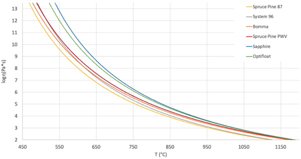
Table 3: Predicted temperatures at specific viscosities.

One of the primary conclusions that we draw from this is that the two industrial glasses, Sapphire and Optifloat, require higher operating temperatures to achieve the same viscosities as the studio glasses. We have noticed that the working range for each glass, which we define as the region or temperature differential between the Working Point and Softening Point, was relatively consistent. The average range is 295 °C and the difference between the largest and smallest range is only 24°C. This consistency across these different glass formulations appears to help with the ability to achieve consistent results with glass printing across multiple glass compositions.
Using the data above in Table 3 and Fig. 2, the new printing parameters suitable for printing with a previously untested glass can be estimated by mapping the equivalent viscosity of a new glass to those of previously tested and calibrated glass compositions. The VFT equation is used for this “Viscosity Matching”, setting the right-hand side of the VFT equation for two different glass bodies equal to the same viscosity and therefore also each other, as shown below. If all of the VFT constants and an input temperature for one glass are known, the corresponding equivalent viscosity temperature of the other glass can be calculated.

New print parameters can be derived based on the behavior of known benchmark glass compositions. This was primarily measured through two parameters: the object weight and the extrusion temperature. The control setpoints on G3DP3 are monitored with a thermocouple and the extrusion temperature of the glass is measured with an IR camera as described below.
2.3. Thermal Imaging, Temperature Measurement, Viscosity Matching
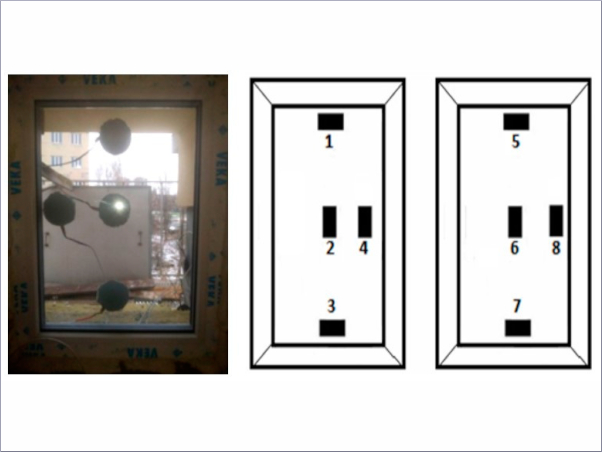
Thermal imagery was captured with an Optris PI 640i G7 thermal camera operating at 7.9 μm with an assumed emissivity of 0.98. This camera is particularly well suited for measuring the behavior of molten glasses because the emissivity of most glasses stays very close to unity over a wide range of temperatures. This provides two critical benefits: the emissivity doesn’t need to be adjusted based on the target temperature and the glass body acts as a nearly black body enabling the disregard of high or low temperature reflections that otherwise greatly influence measurement (Thompson et al. 2021)(Optris GmbH, n.d.).
Short videos of glass printing were taken during the printing of objects. The maximum temperature from video frames and recorded. Figure 3 shows the temperature recorded during the printing of one with each of four glasses used in the G3DP3 system with thermal monitoring.
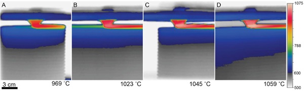
Table 4: Fabrication details for sample objected studied with thermography.

Comparing the corresponding experimental weights from test objects to the software-predicted weight of each object provided additional insight into the viscosity during each print. The set temperature for the print was chosen based on the model described in Section 2.2 and the variations from predicted mass (listed in Table 3) provided additional insight into how much the temperature should be adjusted for future production.
For the development of process parameters for Optifloat, it was possible to utilize the previously successful setpoints to predict a target flow temperature for this new glass. Specifically, the measurement of an extrusion temperature of 1023°C for Spruce Pine PWV was translated to an equivalent set point of 1037°C in Optifloat using Equation 3 and the constants shown in Table 2. Given the numerous sources of error that impact this calculation, it is expected that differences will be observed during operation of the G3DP3 system and the observed mass error of 3.2% is relatively small. This study of multiple glass compositions and implementation of thermography has led to a greater understanding of how glass flows through the G3DP3 and shortened the calibration time for printing with new glass formulations.
3. Processing Container and Float Glass for 3D Printing
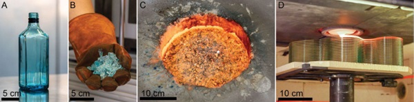
The container or container glass for this project was sourced from a recycling company, Glass Half Full(New Orleans, LA). Specifically the product was a Bombay Blue L1 glass cullet, referred to in this paper as Sapphire glass. The containers were broken down to an average particle diameter of 3.5mm. The glass was melted in a JenKen AFG Double Wall Crucible Kiln, at 119oC. The kiln was filled withapproximate 10 kg batches of cullet preheated to 621oC in an oven. A batch was added every 1.5 hoursto allow the system to equalize to the set temperature. Once full, the kiln was held at 1190oC for 12 hours of conditioning, after which the glass was gathered (pulled from the kiln using a gathering ball)and loaded into G3DP3 to print.
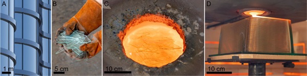
Postconsumer float glass in the form of windows can be taken from deconstructed buildings, broken auto glass, and commercial glazing waste among other sources. For these experiments, to avoid any opportunities for contamination, we used Optifloat float glass provided directly by Pilkington. The glass was crushed with a hammer and the resulting cullet was 12 cm along its largest dimension. The same procedure for filling the JenKen kiln with container glass was used with the exception that the kiln temperature was set to 1218 oC.
4. Printing with Recycled Industrial Glasses
4.1. Validating New Glasses for Additive Manufacturing
The viscosity matching technique described in Section 2 was used to predict an initial set point for the printer extrusion temperature. In parallel, a test melt was produced in the JenKen kiln and a glass rod was manually formed. Using this glass rod, a simple bend test was conducted in the annealing ovens and an average was taken following studio glass principles outlined by Henry Halem (2006).
Temperature set points for the melting furnace, nozzle furnace and print chamber were chosen for each glass to produce an output flow at the predicted viscosity set point. Once the machine was operating, the control temperatures were adjusted to get the output flow to an appropriate range, as monitored by the thermal camera.
After complete objects were fully printed, their weights were compared with the predicted weights and the control temperatures were further adjusted to optimize settings. One of the test objects that was printed out of each glass was Material Ticks, an art series that looks at the dynamic response of programmed deviations from the path of a flat wall leading to glass drips (Fig. 6). The drip sizing provides a visually compelling artifact that shows viscosity frozen in time, enabling a visual comparison of the mobility of the glass at the given temperature settings.
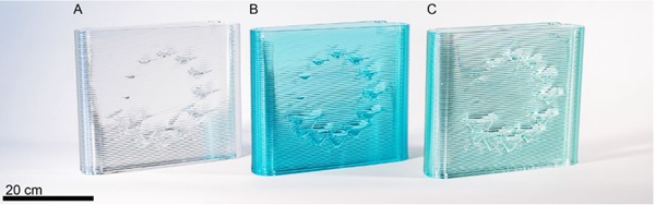
We initially hypothesized that the differences in glass composition (which are easily perceived when manually forming the glass) would similarly be mapped visually into each of the printed glass artifacts. Instead, a remarkable consistency of the glass drips between materials was observed. Two primary conclusions were drawn from this set of experiments. First, the printer can very effectively be recalibrated for different glass formulations; Second, with consistent settings in a viscosity space (viscosity matching), the resulting outputs of the printer are remarkably similar.
4.2. Printing on sheet glass
The use of float glass opens the design space of printing directly onto a sheet of float glass, because of their matched material and coefficient of thermal expansion qualities. Matching thermal expansions across different glasses is a challenging task and a poor match reduces the strength of the bondsbetween the two (Seel et al. 2018). In this study, Optifloat was used, but these same principles apply to other float glasses as well. The added thickness of the sheet glass was programmed into the system and selected before each print. Successful prints were achieved on 3.2, 6.4, 9.5 mm sheets of glass. The glass sheets were preheated on the G3DP3 standard ceramic build plate to just above their annealing temperature to stabilize the glass for loading into the glass printer. The typical printing process was then run with the addition of a vertical offset from the build plate to account for sheet glass thickness.
This approach to fabrication can quickly produce 2.5D structures, often called rib on plate structures. This geometry is used frequently for relatively lightweight but stiff structures as compared to solid slabs of the same materials. These are found widely in aerospace and in telescope mirrors (Zirker 2005)and in architectural applications of large glass panels that require stiffening (Pfarr and Louter 2023). The feasibility of printing on glass was manually demonstrated by (Seel et al. 2018) and the ability to print glass on sheets opens a space where the structure is transparent but also visible, presenting an opportunity to integrate it as an architectural design element.
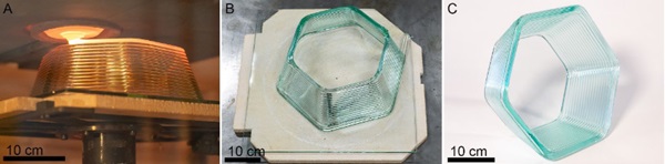
As part of this initial exploration, two designs were tested. The first was a tapered hexagonal extrusion, (shown in Figs. 7 & 8). This test object provided an opportunity to validate this method with a straightforward design that can later be tessellated, while calibration of the interaction of the printed material with the sheet glass served as the focus of this experiment.
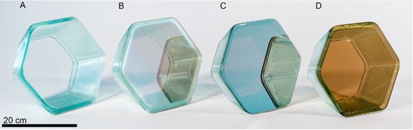
In addition to printing on a sheet of the same Pilkington Optifloat that was used as feedstock, experiments were conducted on different Pilkington products with an array of high temperature coatings, the results of which are shown in Figure 8.
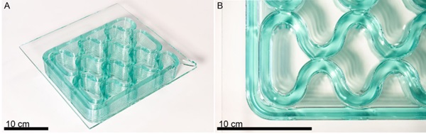
The second design tested, a rib on plate structure, was a cellular fill optimized for the glass printer and modeled after the glass-thermoplastic composite generated by Pfarr and Louter (2023). The form, shown in Figure 9, is characterized by gentle curvatures and set up to generate fusion between adjacent beads of glass. The success of both types of printing give confidence that with this methodology, the remelted and printed glass is still well matched from a thermal expansion perspective with the raw sheet glass. It was observed that any ceramic particles on the build plate would become embedded in the sheet. Since the sheets are already at their annealing temperature, depositing high temperature glass on the surface heats the bottom layer of the sheet enough to distort it. It is expected that transitioning to a build plate with a different material may reduce or eliminate this effect.
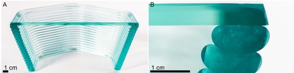
Before implementing this at a larger scale, structural tests are required to characterize the strength of the bond between the first layer and the sheet glass plate. A cross-section of the preheated plate glass to molten printed glass bond and interface between printed beads is visible in Figure 10.
5. Discussion
This work successfully demonstrates G3DP3 can be used to additively manufacture a wide range of different objects out of different glass formulations. These glasses have a higher melting point and distinct characteristic behavior from the glass formulations previously printed. Furthermore, we have demonstrated a workflow for adjusting printing parameters to accommodate new glass formulations in 3DGP3. The focus of this research was to test the feasibility of printing recycled soda lime glass from two predominant streams, float glass and container glass. The authors believe that, given the similarity of float and container glasses, these results can be used to print from other sources of glass. Future work could involve collaboration with glass recycling centers to determine 3DGP3’s sensitivity to post consumer contamination. Characterizing or improving the printing process to be less sensitive to material variation could relieve stress in upstream sorting and cleaning prior to printing the glass into new products or construction materials.
Based on this research, a few variants of the next generation molten glass 3D printer, G3DP4, could succeed Evenline’s G3DP3. For example, the aspect ratio of the build chamber could be changed to generate a large area, low height version designed for printing on large sheets of float glass for large scale architectural facade development. The size of the cellular fill pattern printed on Optifloat (Fig. 9)is smaller than what could be implemented with previous generation of the printer and highlights progress in both the material and a specific class of geometries that can be 3D printed in optically transparent glass. We hope to pursue a project that utilizes G3DP4 to print on much larger sheets of glass. Another variant may include further expansion of the molten glass printer’s operating temperatures to 1700 oC to allow for the printing of glass with higher melting temperature, such as borosilicate, silica, and even lunar regolith.
Acknowledgements
We thank the Rochester Institute of Technology’s College of Art and Design for supporting Evenline’s research in molten glass 3D printing. Specifically, Todd Jokl, Suzanne Peck, David Schnukel, Brendan Miller and Will Tracy were instrumental in this effort. We want to thank Raphael Abel for his design work, help with recycling and operation of the printer. We also thank Kyle Sword, Shona Taylor and the rest of the team at Pilkington Glass North America, part of Nippon Sheet Glass Company, Ltd (NSG). We thank Priscilla Lo and Bella Walters for assistance operating the glass printer and cold working, as well as Mackenzie Serwa for her photography. Lastly, we thank the team at Glass Half Full, Greg Fiddler from Spruce Pine Batch, and Tony Marino from AGI. Composition measurements were performed at the MIT Electron Microprobe Facility.
References
Dhir, Ravindra K., and University of Dundee, eds. 2001. Recycling and Reuse of Glass Cullet: Proceedings of the International Symposium, Organised by the Concrete Technology Unit and Held at the University of Dundee, Scotland, UK on 19 - 20 March 2001. London: Telford.
Fluegel, Alexander. 2007. “Glass Viscosity Calculation Based on a Global Statistical Modelling Approach.” Glass Technology 48 (1).
Halem, Henry. 2006. Glass Notes, a Reference for the Glass Artist. 4th edition. Franklin Mills Pr.
Inamura, Chikara, Michael Stern, Daniel Lizardo, Peter Houk, and Neri Oxman. 2018. “Additive Manufacturing of Transparent Glass Structures.” 3D Printing and Additive Manufacturing 5 (4): 269–83. https://doi.org/10.1089/3dp.2018.0157.
Jordan, John M. 2018. 3D Printing. The MIT Press Essential Knowledge Series. Cambridge, Massachusetts London, England: The MIT Press.
Klein, John, Michael Stern, Giorgia Franchin, Markus Kayser, Chikara Inamura, Shreya Dave, James C. Weaver, et al. 2015. “Additive Manufacturing of Optically Transparent Glass.” 3D Printing and Additive Manufacturing 2 (3): 92–105. https://doi.org/10.1089/3dp.2015.0021.
Oikonomopoulou, Ivneet Singh Bhatia, Wilfried Damen, Felix Van Der Weijst, and Telesilla Bristogianni. 2020. “Rethinking the Cast Glass Mould.” Challenging Glass Conference Proceedings, September, Vol. 7 (2020): Challenging Glass 7. https://doi.org/10.7480/CGC.7.4662.
Optris GmbH. n.d. “Non-Contact Temperature Measurement Glass Industry.” Accessed March 2, 2024. https://www.optris.com/en/download/glass-industry-brochure/?wpdmdl=160688&refresh=65da90dc0e37c1708822748.
Pfarr, Daniel, and Christian Louter. 2023. “Prototyping of Digitally Manufactured Thin Glass Composite Façade Panels.” Architecture, Structures and Construction 3 (2): 263–73. https://doi.org/10.1007/s44150-022-00080-7.
Seel, M., R. Akerboom, U. Knaack, M. Oechsner, P. Hof, and J. Schneider. 2018. “Fused Glass Deposition Modelling for Applications in the Built Environment: Schmelzschichten Aus Glas Für Anwendungen Im Bauwesen.” Materialwissenschaft Und Werkstofftechnik 49 (7): 870–80. https://doi.org/10.1002/mawe.201800075.
Thompson, James O., Daniel B. Williams, Rachel J. Lee, and Michael S. Ramsey. 2021. “Quantitative Thermal Emission Spectroscopy at High Temperatures: A Laboratory Approach for Measurement and Calibration.” Journal of Geophysical Research: Solid Earth 126 (7): e2021JB022157. https://doi.org/10.1029/2021JB022157.
Tooley, Fay V. 1984. The Handbook of Glass Manufacture. 3rd ed. Vol. 1. 2 vols. Books for the Glass Industry Division Ashlee Publishing Co., Inc.
Zirker, Jack B. 2005. An Acre of Glass: A History and Forecast of the Telescope. Baltimore: Johns Hopkins university press.