Article Information
- Digital Object Identifier (DOI): 10.47982/cgc.9. 475
- Published by Challenging Glass, on behalf of the author(s), at Stichting OpenAccess.
- Published as part of the peer-reviewed Challenging Glass Conference Proceedings, Volume 9, June 2024, 10.47982/cgc.9
- Editors: Christian Louter, Freek Bos & Jan Belis
- This work is licensed under a Creative Commons Attribution 4.0 International (CC BY 4.0) licence.
- Copyright © 2024 with the author(s)
Authors:
- Alina Katzera
- Michael Engelmann
- Bernhard Weller
Dresden University of Technology, Institute of Building Construction, Dresden

Abstract
Fluids in the cavity can be used to integrate additional functions into insulating glazing. However, the high permanent load exerted by the fluid on the glazing and surrounding components is problematic. Conventional design methods result in large adhesive joints, which are not desirable from an aesthetic point of view. ETAG 002-1 is typically used for the design of structural adhesive bonds for use in structural glazing façades. However, the calculation is considered to be conservative. In particular, it is criticised for its deterministic safety concept. Therefore, in recent years, a number of researchers have looked at different methods for the design of adhesive joints. Such methods are presented by the Fachverband Konstruktiver Glasbau e.V. in the Technical Note FKG 01/2021.
A further approach is presented by Drass & Kraus (2020, 2021a, 2021b), who proposes an approximation to the semi-probabilistic safety concept and thus to the current Eurocode 0 design standard by determining a material safety factor. This paper is concerned with the design of a load-bearing adhesive joint for use in a fluid-filled insulating glass unit. A specific façade element is used as an example for the calculations. Three dimensioning methods are compared: the analytical method according to ETAG 002-1, a numerical method according to Technical Note FKG 01/2021 and the approximation of a semi-probabilistic safety concept according to Drass & Kraus (2020, 2021a, 2021b). The results show significant differences between the design methods in terms of utilisation.
1.Introduction and current situation
Adaptability to environmental conditions and external influences is a key to further energy optimisation of the building envelope. Current glass façades with fixed characteristics cannot respond adequately to changes in solar radiation or temperature during the day and over the seasons. Dynamic glazing and adaptive solutions are therefore becoming increasingly important in façade construction. In addition to established solutions such as electrochromic glazing, research and development activities are currently investigating various concepts for adaptive, multifunctional building envelopes. One innovative approach is the use of fluids in the pane cavity of insulating glass units. The fluid can be thermally regulated (InDeWaG 2023), mixed with functional particles (Fluidglass 2024) or even used to cultivate algae (Energie Zukunft 2020). This paves the way for the design of ultra-low energy buildings. In parallel with the building physics and automation issues, there is a particular need for research into the joining techniques for the individual panes due to the direct contact with a fluid.
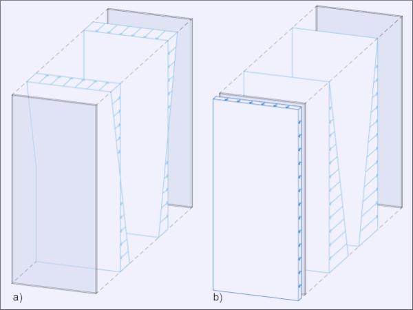
In the first completed pilot projects (Fig. 1), the high hydrostatic pressure acting on the glazing, and therefore on the edge seal, is taken up by means of attached clamping bars. These external mechanical clamps ensure that the edge seal is able to fulfil its function permanently. However, external mechanical clamps interfere with the desire for smooth external surfaces that define the visual appearance of slim glass facades. This high design requirement can only be met by a structurally bonded edge seal system designed for use in a fluid medium.

The aim of the research project fluidIGU was therefore to develop a structural glazing system for fluid-filled façade elements. The adhesives used are exposed to high mechanical and chemical stresses due to the fluid in the pane cavity. Chemical resistance has been experimentally proven (Joachim et al. 2022a, Joachim et al. 2023). Resistance to mechanical stress must be demonstrated both experimentally and by calculation. For structurally bonded glass façades, ETAG 002-1 is the current standard. The proof of the adhesive joint is provided by limiting the adhesive joint stress.
The strength of the adhesive joint is highly dependent on the duration of exposure. This is because the polymeric structure of adhesives has a strong creep tendency. As a result, a permanent load is usually the more critical load for adhesive joints and additional safety factors must be applied. In the following, two other dimensioning methods are compared with the ETAG 002-1 method in order to gain a better understanding of the use of the bond.
2. Methods for Dimensioning an Adhesive Joint
2.1. ETAG 002-1
The conventional dimensioning and verification of a structural adhesive joint in glass construction is based on a deterministic safety concept. ETAG 002-1 from 2012 is still the technical standard to be used for this (ETAG 002-1). It provides an analytical approach to the calculation. Here, the load-bearing capacity of the adhesive jointis reduced by a global safety factor γtot = 6 for short-term loads. The check is carried out in the area of the adhesive joint under maximum stress at the unfactored load level. For permanent loading an additional global creep factor γc≥ 10 has to be applied. (ETAG 002-1, Annex 2)
The design according to ETAG 002-1 is heavily criticised in view of the current state of knowledge on load-bearing silicone bonds (Aßmus 2019 p. 191 pp, Fildhuth et al. 2021 p. 10, Maniatis et al. 2015). The resulting adhesive joint dimensions are considered uneconomical due to the excessive safety factors, and the actual utilisation of the adhesive joint is uncertain due to the great simplification. As a result, there are other alternative approaches to adhesive joint design.
2.2. Technical Note FKG 01/2021
In 2021, the FKG (Fachverband Konstruktiver Glasbau) published the Technical Note FKG 01/2021. It describes the verification and dimensioning of the adhesive joint using a numerical equivalent model (spring model). The calculation method represents a compromise between manageable calculation effort and higher calculation accuracy. For sizing and verification purposes, the silicone joint is modelled using a series of linear force-displacement springs with appropriate material properties. The spacing of the springs depends on the discount selected and determines the bond area assigned to the spring.
The verification is also based on the deterministic safety concept. Based on the more accurate calculation method, the global safety factor for short-term stresses γtot can be reduced from 6 to 4 compared to ETAG 002-1 in consultation with the adhesive manufacturers and the relevant building authority. The determined spring tension forces are converted into an adhesive joint stress over the assigned area. The check must always be carried out on the spring subjected to the maximum load.
2.3. Drass & Kraus
Current Eurocodes are based on semi-probabilistic design and verification. In several publications, Drass & Kraus describe the approximation of a semi-probabilistic safety concept for the design of structurally adhesive joints. (Drass and Kraus 2020, Drass and Kraus 2021a, Drass and Kraus 2021b) For this purpose, a material-specific partial safety factor was determined and calibrated using experimental data. This procedure is currently not regulated for adhesive joints. The verification is carried out at the design load level in accordance with the safety concept. The type of calculation (analytical/numerical) is not specified.
3. Dimensioning an Adhesive Joint for Use in Fluid-Filled Façade Element
3.1. Façade element
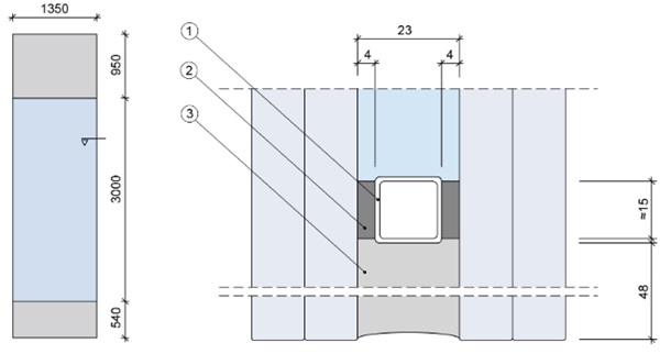
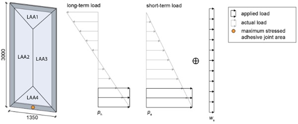
The façade element used for the design is based on a floor-to-ceiling glazing with a height of h = 3000 mm and a width of b = 1350 mm (Fig. 2, left). The pane cavity filled with fluid is d = 23 mm. The fluid consists of water and ethylene glycol (mixing ratio 7:3). This allows the façade element to be actively heated and cooled. The glazing unit can be extended with a second gas-filled pane cavity, but only one pane cavity is assumed for the calculation.
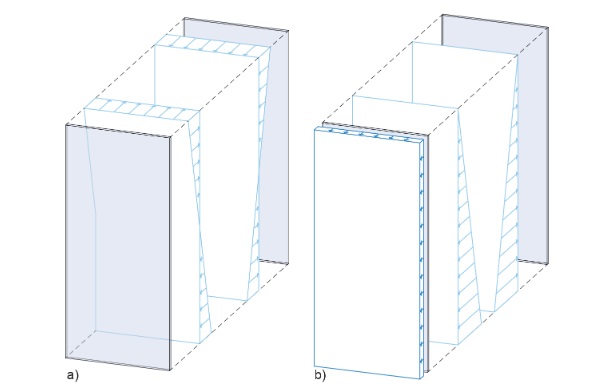
A new high-performance system is to be used for the edge seal. It uses a two-stage principle based on conventional gas-filled insulating glazing (Fig. 2, right). By combining two adhesive joints, the main functions of the edge seal, namely sealing and load transfer, are divided between suitable adhesives. The joint dimensions have been approximated based on ETAG 002-1 design under short term loading.
For the purposes of dimensioning and verification in this article, only the load bearing adhesive joint ((3) in Fig. 2) is considered as the load-bearing functional layer. Experimental tests have shown that Sikasil® SG-550 is the preferred adhesive for this purpose (Katzera 2023, p. 113).
3.2. Load assumptions
Façade elements are subject to a variety of stresses, which are categorised into different types for this investigation. Table 1 gives an overview of the types of stresses, which are divided into physical, mechanical and chemical stresses. Mechanical stress is actually part of physical stress, but is listed separately here because of its importance.
Table 1: Overview of stress types.
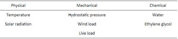
For the mathematical verification, the expected mechanical stresses are decisive.
The fluid exerts high pressure on the front and rear windows and surrounding components in the pane cavity. The water-ethylene glycol behaves like water at room temperature. For this reason, the pressure that builds up is also known as hydrostatic pressure. The pressure increases as the panel height increases, resulting in a triangular load pattern.
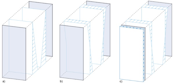
At 20 °C this gives a mixed density of ρm,20°C = 1.03 g/cm3, from which the hydrostatic pressure at the base of the h = 3 m high glazing and the gravity of g = 9,81 m/s2 gives ph (3 m)= ρ x g x h ≈ 30 kN/m2(Fig. 3a). By connecting a specific vacuum system, the level of hydrostatic pressure at the base point is reduced to ph (3 m) = 15 kN/m2 (Fig. 3b). The system technology for creating a negative pressure in the pane cavity is described in more detail in (Joachim 2022b) and (Katzera 2023).
The wind loads are calculated according to Eurocode 1. For a generic example building, a size of 40 m x 20 m x 35 m in wind load zone 1, inland, and a load application area of 4 m2 is assumed. This gives a calculated wind pressure of wd = 0.76 kN/m2 and wind suction of ws = -1.14 kN/m2 (EN 1991-1-4, DIN EN 1991-1-4/NA). In addition to the amount of the load, the direction of the load is also important: wind suction is the dominant load combination (Fig. 3c).
A horizontal line load is used as the equivalent live load for safety glazing in accordance with DIN 18008-4. The glazing assumed in the example design is of category A. Accordingly, the full load must be transmitted through the glazing. Therefore, a linear compression load of qk = 1.0 kN/m at a height of 1 m above the top of the floor (DIN 18008-4) must be assumed. As it can be assumed that a compressive load will relieve the tensile load on the edge bond, and the load height is also relatively small, the live load is considered negligible.
3.3. Load cases and load combinations
The mathematical verification is carried out for different load cases and combinations of load cases. The load cases essentially correspond to the load assumptions described above (Section 3.2): hydrostatic pressure and wind suction. The hydrostatic pressure load case refers to the condition with intact system technology for generating negative pressure. As a third load case, an increase in pressure due to failure of the negative pressure technology is recognised as an exceptional load case.
The simultaneous occurrence of several mechanical loads is represented by load combinations. Essentially, a distinction must be made between the basic combination and the exceptional load combination. The basic combination combines the hydrostatic pressure and wind suction load cases. In the exceptional load combination, a failure of the connected vacuum technology is added. To be on the safe side, a simultaneous occurrence of wind suction is also assumed.
Mathematical verification of the bond must be carried out under both, short term and long term loading. The hydrostatic pressure load case with intact vacuum generation system technology forms the permanent load (Fig. 4a). The critical load combination for the short term check is the exceptional load combination of a failure of the vacuum system with a simultaneous wind suction load (Fig. 4b).
3.4. Stress analysis
The three calculation methods mentioned in section 2 are used. Table 2 summarises the main assumptions made for the stress analysis.
Table 2: Stress analysis assumptions.
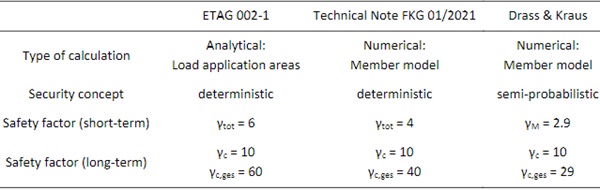
A member model is used for the numerical calculation, which differs from the Technical Note FKG 01/2021, which suggests a spring model. However, this makes no difference for a bond subject to tensile stress. In the deterministic safety concept, a characteristic load level (Ek) is calculated on the loading side. For the semi-probabilistic safety concept, a partial safety factor of γG = 1,35 is applied for permanent loads and γQ = 1,5 for variable loads according to EN 1990. This results in stresses at the design loading level (Ed). For the ETAG 002-1 global creep factor, there is no known alternative approach for verification under permanent loading. Therefore, the creep factor is used in all three calculation methods.
According to ETAG 002-1
For stress analysis in accordance with ETAG 002-1, the bond stress is calculated in the maximally stressed bond area at a unfactored load level. This is determined by the load application areas. Figure 4 shows the load assumptions made and the distribution of the load application areas.
The mathematical verification gives Ek = 0.15 N/mm2≤Rdes = 0.20 N/mm2 for short-term loading and Ek = 0.21 N/mm2 > Rdes = 0.02 N/mm2 for permanent loading under hydrostatic pressure.
According to Technical Note FKG 01/2021
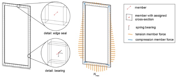
A member model is used as a more accurate calculation method for stress analysis in accordance with the Technical Note FKG 01/2021. The calculations are performed using the finite element software RFEM 5.15.01 from Dlubal Software. The laminated glass panes are modelled using surface elements with an equivalent glass thickness d* without effective shear bond (DIN 18008-2, A.6). The distance between the surface elements is equal to the distance between the panes (bSZR = 23 mm). The bond is modelled using members perpendicular to the glass surface. The length of the rods corresponds to the thickness of the bond. The rods are assigned the mechanical properties of the adhesive material and a cross section corresponding to the rod spacing and the size of the joint. The material properties of the adhesive are defined as isotropic non-linear elastic material models based on experimental investigations. A square cross-section is aimed for. Figure 6 shows the modelled façade element with two detailed sections.
The load is applied under unfactored load levels for the two load scenarios. For verification, the maximum stresses are determined via the normal member forces in the load-bearing connection. The mathematical verification for the design relevant short term load combination gives Ek = 0.18 N/mm2≤Rdes = 0.30 N/mm2. The verification for a permanent load under hydrostatic pressure gives Ek = 0.08 N/mm2 > Rdes = 0.03 N/mm2.
According to Drass & Kraus
Drass & Kraus determined an adhesive-specific material partial safety factor by approximating a semi-probabilistic safety concept. The procedure described in Drass & Kraus 2020 was applied to the silicone adhesive Sikasil® SG-550 used as a structural adhesive; the calculation is listed in Katzera 2023 (Katzera 2023, p. 233 pp). Based on experimental tests, the material safety factor is γM = 1.94. A numerical member model is used for the check, analogous to the approach described in the Technical Note FKG 01/2021. The load is applied at the design load level. The mathematical verification results for the exceptional load combination as a short-term load at Ed = 0.19 N/mm2 ≤ Rd = 0.36 N/mm2. For the permanent load at Ed = 0.11 N/mm2 > Rd = 0.06 N/mm2.
3.5. Comparison of the results
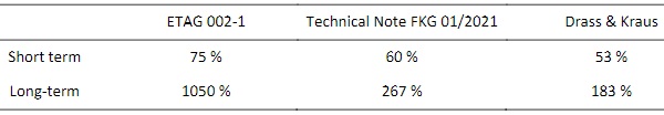
Table 3 summarises the results for the three calculation methods in terms of percentage utilisation.
According to all three calculation methods, the verification for the exceptional load case combination of increased hydrostatic pressure and simultaneous occurrence of wind suction as a short-term load is achieved. For hydrostatic pressure with intact system technology to generate negative pressure as a permanent load, the verification cannot be achieved.
The differences between the calculation methods are reflected in the stress levels. The ETAG 002-1 stress verification shows a more than tenfold overload of the adhesive joint. Conversely, the ETAG 002-1 design would require the adhesive joint to be more than ten times wider. In contrast, the semi-probabilistic approximation verification results in less than twice the adhesive joint overload. However, this method is currently not in use and is not part of the standard.
Table 3: Comparison of results in percentage load factors.
4. Discussion and conclusions
This article looks at different methods of dimensioning an adhesive joint for use in fluid-filled façade element glazing. Conventional dimensioning in accordance with ETAG 002-1 has been compared with the method described in the Technical Note FKG 01/2021, which is already used in practice. The design was also carried out using a semi-probabilistic approximation for adhesive joints, which is not currently an application-oriented procedure.
The verification was carried out for the exceptional load combination of increased hydrostatic pressure and simultaneous wind suction as a short-term load. For the assumptions made for the element dimensions and the adhesive joint geometry, the verification for the short-term load can be achieved according to all three calculation methods. The differences between the design methods can be seen in the degree of utilisation. The questions remains which model represents reality closest with sufficient degree of safety? To answer this question, further experimental studies on the planned original scale are required. Results from scaled tests cannot be adequately transferred due to the influence of the load application areas (Katzera 2023, p. 240 p).
For the verification under permanent loads, the hydrostatic pressure with intact system technology to generate a negative pressure is the decisive load. An additional safety factor of γc = 10 was selected for the verification in all three calculation methods. Taking this into account, it was not possible to achieve the verification using any of the three methods, despite the lower load level. The hydrostatic pressure is therefore the design relevant load as a permanent load.
Adhesive joint design according to ETAG 002-1 has been heavily criticised for its conservative approach and uneconomical use of adhesives. Whilst alternative approaches are known for verification under short-term loading, there are no such approaches for design under permanent load effects. However, it can be deduced from the following various experimental studies that the load carrying capacity of the adhesive bond is actually higher than the reduction of the additional safety factor of γc ≥ 10 according to ETAG 002-1.
- A creep factor equivalent to γc ≤ 2 has been investigated in small creep tests and a service life of almost 40 years has been predicted for Sikasil® SG-550 with a bond thickness of 23 mm (Katzera 2023, p. 144 pp).
- The calculated stresses were realistically verified in component tests. None of the specimens cracked or leaked throughout the test programme. Again, the calculated stress on the bond was many times greater (390–167 %) than the load carrying capacity. (Katzera 2023, p. 171 pp).
Therefore, it remains to be discussed whether the creep factor γc ≥ 10 to be applied according to ETAG 002-1 is justified. The authors see an urgent need for research into the resistance of silicone joints to permanent loading.
Further design measures must be taken in order to meet the design requirements using the calculation methods and safety factors listed. Possible measures include reducing the panel width to minimise the load application area, reducing the panel height to reduce the hydrostatic pressure and increasing the width of the adhesive joint to reduce the engineering stress. Other measures include choosing a stronger panel structure to reduce deformation and increasing the negative pressure in the pane cavity to reduce tensile stresses in the adhesive joint.
Acknowledgements
The study results from the research project fluidIGU funded within the KLEBTECH network through the Central Innovation Programme (ZIM) by the German Federal Ministry for Economic Affairs and Climate Action (BMWK). Special thanks go to the project partners Bollinger + Grohmann Consulting GmbH and ADCO Technik GmbH for the good cooperation and technical support.
References
Aßmus, E. Klebverbindungen in flüssigen Medien für den konstruktiven Glasbau. Adhesive Connections in Fluids for Glass Constructions [Dissertation] Technische Universität Dresden (2019) https://nbn-resolving.org/urn:nbn:de:bsz:14-qucosa2-724310
DIN 18008-2:2020-05 Glas im Bauwesen – Bemessungs- und Konstruktionsregeln – Teil 2: Linienförmig gelagerte Verglasungen (2020)
DIN 18008-4: 2013-07: Glas im Bauwesen – Bemessungs- und Konstruktionsregeln – Teil 4: Zusatzanforderungen an absturzsichernde Verglasungen (2013)
DIN EN 1991-1- 4/NA:2010-12: Nationaler Anhang – National festgelegte Parameter – Eurocode 1: Einwirkungen auf Tragwerke – Teil 1-4: Allgemeine Einwirkungen – Windlasten. https://dx.doi.org/10.31030/1723628
Drass, M.; Kraus, M. A.: Adé ETAG 002 – A Eurocode – compliant design concept for silicone adhesive joints. In: Engineered Transparency 2021 (2021a) https://doi.org/10.1002/cepa.1637
Drass, M.; Kraus, M. A.: Dimensioning of silicone adhesive joints: Eurocode-compliant, mesh-independent approach using the FEM. In: Glass Structures & Engineering (2020) https://doi.org/10.1007/s40940-020-00128-4
Drass, M.; Kraus, M. A.: Semi-probabilistic design of silicone adhesive joints: A Eurocode-compliant approach using the finite element method. In: Bauingenieur (96) (2021b) https://doi.org/10.37544/0005-6650-2021-01-02
EN 1990 Eurocode: Basis of structural design (2002) https://dx.doi.org/10.31030/3291403
EN 1991-1- 4 Eurocode 1: Actions on structures –Part 1-4: General actions –Wind actions (2005). https://dx.doi.org/10.31030/1625598
Energie Zukunft Wissenschaftsjahr 2020 – Bioökonomie: Ein Wandel der Wirtschaftist angesichts der Klimakrise notwendig. https://www.energiezukunft.eu/umweltschutz/ein-wandel-der-wirtschaft-ist-angesichts-der-klimakrise-notwendig/ (access: 03-2024)
ETAG 002-1: Guideline for european technical approval for structural sealant glazing kits – Part 1: Supported and unsupported systems (2012)
Fachverband Konstruktiver Glasbau e.V.: Merkblatt FKG 01/2021 Tragende Silikonklebstoffe im Konstruktiven Glasbau (2021)
Fildhuth, T.; Scheible, F.; Luible, A.; Walach, R. Tragverhalten und Einsatz breiter SG-Silikonverklebungen In: Glasbau (Weller, B.; Tasche, S. [eds.]) (2021)
Fluidglass Collaborative project on developing of the new innovative concept for multifunctional solar thermal glass façades systems https://www.fluidglass.eu/ (access: 03-2024)
InDeWaG Industrial Development of Water Flow Glazing Systems https://www.indewag.eu/ (access: 06-2023)
Joachim, A. F. L., Glogowski, M., Kothe, C., Nicklisch, F. & Weller, B.: Leak test for the material selection of a bonded edge seal for fluid-filled façade elements. In: International Journal of Adhesion and Adhesives.(2022a) https://doi.org/10.1016/j.ijadhadh.2021.103082
Joachim, A. F. L., Nicklisch, F. & Weller, B.: Versuchsprogramm zur Klebstoffuntersuchung fluidgefüllter Isolierverglasungen. In: Glasbau 2023. (2023) https://doi.org/10.1002/9783433611739.ch19
Joachim, A. F. L., Nicklisch, F., Freund, A. & Weller, B.: Examination of the Load-Bearing Behavior of a Bonded Edge Seal for Fluid-Filled Insulating Glass Units. In: Challenging Glass Conference Proceedings, Volume 8 (2022b)
Katzera, A. F. L.: Klebverbindungen unter Einfluss von Flüssigkeit. Adhesive Connections Exposed to a Fluid. [Dissertation] Technische Universität Dresden (2023) https://nbn-resolving.org/urn:nbn:de:bsz:14-qucosa2-891530 Maniatis, I.; Siebert, G.; Nehring, G. Dimensionierung von Klebefugen aus Silikon mit beliebiger Geometrie. In: Stahlbau (84)(2015) https://onlinelibrary.wiley.com/doi/10.1002/stab.201590086


 demonstrator at Glass Technology Live during Glasstec 2024 (© Cas Maertens).")