Authors: Simona Bianchi, Guido Lori, Valerie Hayez, Mauro Overend & Giampiero Manara
Source: Glass Structures & Engineering
DOI: https://doi.org/10.1007/s40940-024-00255-2
Abstract
Creating safer and more resilient building facades has become a primary concern in contemporary design, particularly in earthquake-prone regions, where there is a potentially high impact on financial, social and environmental losses. Glazed curtain wall systems are widely used in modern architecture. Yet, despite decades of research efforts aimed at enhancing the understanding of their seismic behaviour, it is not clear how design choices affect the response of glazed facades. This is crucial given the wide range of glass, framing and joint variations that are at our disposal. With a focus on unitized curtain walls, this paper provides insights into the influence of design variables on façade seismic response by means of an extensive experimental campaign and an associated parametric study to test alternative designs under both quasi-static and dynamic loading conditions. The variables considered included variations in unit dimensions, glass and joint aspect ratios, joint and framing detailing, and support conditions. This research delves into a statistical analysis of the experimental results, in order to define parameters such as glass and façade unit rotations, frame elongations and distortions, utilization factors at different intensity levels. The results provide insights that guide façade design decisions for achieving desired seismic performance levels.
1 Introduction
Glazed curtain walls are directly impacted by earthquakes, experiencing inter-storey drift ratios, displacement incompatibilities and inertia forces. Initially, seismic movements can be absorbed by internal gaps and deformations of the façade. However, as deformations increase, specific parts of the façade system may suffer concentrated stresses and damage. This damage can include (a) degradation of gaskets and/or weatherproofing or structural silicone, leading to air and/or water infiltrations; (b) glass breakage, which may not cause human injury, but results in further air permeability, water infiltration and other indirect damages; (c) glass fallout, posing potential risks of injury and life with significant economic consequences (Miranda et al. 2010; Baird et al. 2011). This potential damage highlights two primary concerns: the risk to humans by glass falling from height, potentially leading to injuries and fatalities at street level, and the impact on building downtime and repair costs, hindering the return to normal operations and services due to a compromised building envelope. Therefore, current international building codes (e.g., European and American standards) provide guidelines for properly sizing facade joints and connections, as their design is crucial for enhancing structural performance and accommodating relative motion.
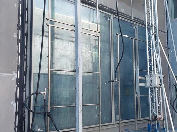
In recent years, numerous research efforts have been undertaken to evaluate the seismic performance of glazing systems, as discussed in Huang et al. (2017), Bianchi and Pampanin (2022) and Momeni and Bedon (2024). These investigations include both experimental and numerical approaches. Experimental studies have primarily focused on assessing the movement and drift capacity of glass panels through in-plane monotonic and cyclic racking testing, bi-directional tests or shake table testing (e.g., Broker et al. 2012; Lu et al. 2016; Memari et al. 2021; Zhuang et al. 2024; Ji et al. 2024). These studies investigated the influence of different glass types and connection systems and identified damage patterns and the effect of in-plane and out-of-plane actions. Additionally, recent experimental tests conducted by Arifin et al. (2020) and Bianchi et al. (2022) (Fig. 1a) have investigated the serviceability of glazed curtain walls at low seismic intensity levels, particularly concerning water and air tightness.
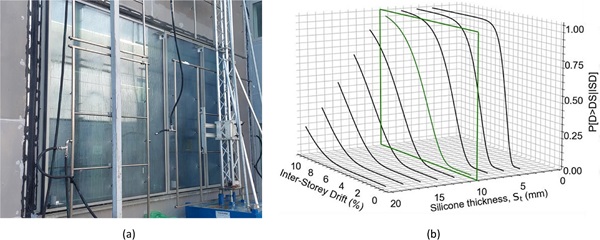
Concurrently, recent research has focused on the implementation of analytical-mechanical and numerical simulations to model the façade behaviour. While some studies have considered finite element modelling of entire façade systems (e.g., Memari et al. 2011; Caterino et al. 2017; Rossetti et al. 2023; Ciurlanti et al. 2023), there is a growing trend towards more refined constitutive model of the silicone behaviour to accurately capture the response of Silicone Structurally-Glazed (SSG) systems (e.g., Nuñez Enriquez 2022; Kimberlain et al. 2022; Hayez et al. 2023). With a strong correlation between numerical simulation and seismic testing, these investigations have shown that simulation-based calculations can effectively predict façade performance in seismic tests. Moreover, these studies have aimed to derive fragility curves (Fig. 1b), which represent the probability of reaching or exceeding specific damage states, for use in risk assessment methods.
While existing literature provides valuable insights, there is a need for further investigation into the direct impact of design variables on façade response. This paper provides new perspectives for improving design practices. As part of an EU-funded research project, SAFE-FACE, led by Delft University of Technology in partnership with Permasteelisa Group, the seismic behaviour of full-scale unitized facades was investigated through an extensive research program (Bianchi et al. 2022, 2024). The project aimed to evaluate both the serviceability performance and the ultimate limit state of various façade designs. As discussed in the following section, the experiments covered a wide range of façade configurations, including dry vs. SSG systems, and various construction details, in particular aspect ratios for glass, overall unit (vision and spandrel), frame, joint detailing and frame properties. As part of the ongoing experimental data post-processing, this paper focuses on presenting the results obtained from design variables and analysing trends in behaviour to provide insights into façade performance based on observed responses. The paper is structured as follows: Sect. 2 describes the parametric configurations considered in the experiments, including specimen dimensions, properties, support conditions, loading types and monitoring system; Sect. 3 delves into the experimental results of the seismic performance, discussing insights from design variables and their impact on response, along with a sensitivity study from the statistical analysis; and Sect. 4 concludes the paper by providing main conclusions and future developments.
1.1 Seismic design of unitized curtain walls
Unitized curtain walls are non-structural components, i.e., they are not considered part of the primary load-bearing structure of a building. However, they should be designed to properly transfer inertial loads to the main structure and accommodate inter-storey drifts. This is a non-trivial performance requirement in performance-based earthquake engineering, because minimizing damage to non-structural components and improving their resilience is crucial for reducing post-earthquake losses.
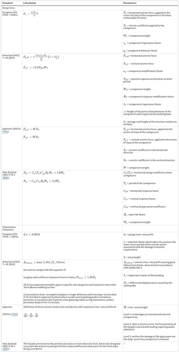
A pivotal aspect of seismic design for unitized curtain walls lies in the design of the connections between the unitized curtain wall panels and the building structure. The impact of seismic action on non-structural components, including their connections and attachments, can be determined by applying seismic forces as required by different international codes (Table 1). Most of them provide calculation methods for both horizontal—in-plane, out-of-plane—and vertical seismic forces (ASCE 7-10 2010, JASS14 1996, NZS 1170.5 2004), enabling comprehensive design considerations. Additionally, the glass panels of the unitized curtain wall experience displacement caused by these seismic forces, highlighting the importance of flexibility and movement capability in façade detailing. It is crucial to design these facades to accommodate building movement without compromising their integrity, with the out-of-plane behaviour particularly affected by the inertia forces while the in-plane behaviour influenced by displacement incompatibility. The façade performance during earthquakes is influenced by the relative displacements within the main building structure.
Therefore, existing standards provide formulations or recommendations for displacements in designing such components (Table 1). These are also accompanied by experimental testing to verify that the unitized curtain wall system meets required seismic resistance standards. For instance, widely used experimental protocols are those outlined in the American Architectural Manufacturers Association (AAMA) standards (AAMA 501.4-09, 2009a, AAMA 501.6-09, 2009b) which requires static and dynamic racking tests. The static racking test assesses the serviceability performance of façade specimens, simulating statically applied horizontal displacements. The dynamic racking test focuses on seismic safety by applying a displacement history comprising sinusoidal motions with progressively higher drift amplitudes, including ramp-up and constant intervals, in order to determine the dynamic drift that causes glass fallout from a glazed curtain wall panel. Other guidelines, such as UNI EN 13830 (2022), only specify the application of racking movement with a minimum of three cycles: movement to one extreme position, to the other extreme position, and returning to the original position. The maximum horizontal movement that the facade can undergo without compromising safety should be recorded. In contrast, the Japanese code (JASS14 1996) also provides specific intensity levels (inter-story drift ratios) to consider for the testing phase.
Table 1 Seismic design criteria - Full size table
Focusing on bonding joints (SSG systems), the design approach involves evaluating the adequacy of joint thickness to accommodate displacement due to seismic racking. In Europe, the ETAG002 (2012) guideline (now superseded by the EAD 090010-00-0404 2018) is considered, where the differential displacement to be accommodated by the joint is determined by the shear modulus of the silicone for different loading levels. For American markets following ASTM C 1401 (2009), specific maximum elongation limits are set for each performance level (drift ratios). The joint's global utilization level is thus assessed based on forces and differential displacements, ensuring that the joint's deformation does not exceed the elongation limit. This approach guarantees the joint's effectiveness in bonding and sealing the facade while withstanding forces, such as seismic forces.
2 Parametric experimental study
A comprehensive experimental campaign was conducted at the Permasteelisa Group laboratory in Vittorio Veneto, Italy, to evaluate the seismic performance of full-scale unitized curtain wall systems. The study focused on various facade details designed following the EN 1998-1 (2004) code (seismic force calculation), the UNI EN 13830 (2022) (testing protocol) and JASS14 (1996) (deformation verification), including dry vs. wet systems, joint dimensions and types of glass and frames, through a series of experiments. This section describes the various facade units tested, the loading protocol considered and the performance indicators monitored or derived analytically from the experimental data.
2.1 Façade configurations
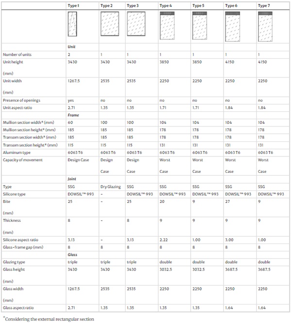
The properties of the façade specimens tested during the experimental campaign are summarized in Table 2, while the adopted connection detailing are presented in Fig. 2.
Table 2 Matrix of façade configurations - Full size table
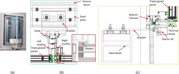
Seven different facade systems (Types 1–7) underwent testing, with variations primarily in dimensions (glass, spandrel and joint). Type 1 configuration also included an operable window in the unit, as depicted in the sketch in Table 2. All configurations featured aluminum extruded profiles for the façade framing. Mullions and transoms were connected via screwed connections, while mullions of different units were linked using male–female joints, incorporating thermal breaks and anti-buckling components. One facade system (Type 2) employed a dry glazing (DG) configuration, consisting of gaskets and mechanical restraints in the connections, while the others had a SSG configuration. DOWSIL™ 993 was uniformly used across all SSG units, with variations in joint aspect ratio. Stack joints along mullions and transoms provided proper clearance to accommodate building movements. The frame design aimed to withstand seismic movements, safeguarding silicone joints from damage (Design Case). An angular steel plate was introduced in the alignment screw connection to prevent it from bearing on the starter sill profile, thus avoiding horizontal sliding of the bottom transom at lower drift levels. This allowed for greater relative vertical movement capacity of the bottom transom compared to the starter sill. However, specific configurations (Type 4, 6, 7) featured restrained bottom transoms, impeding partial rotation and representing a worst-case scenario (Worst Case).
Connection to the main structure involved hooks, brackets and adjusting bolts. The starter sill was connected to the bottom transom using screwed alignment blocks and shear keys. Each unit required two hooks for upper anchorage, with one hook fixed using screws and the other free to move horizontally. This arrangement allowed units to adapt to differential building movements, as well as construction tolerances. Vertical tolerance was achieved through adjusting bolts, while horizontal tolerance was ensured by the clearance between the hook and steel plate.
2.2 Loading type
The seven facade specimens were tested in different phases, each with specific objectives and experimental protocols tailored accordingly. For Type 1 and 2, the focus was on typical code-compliant procedures, assessing post-earthquake serviceability for air tightness and water penetration. Types 3–7 were instead subjected to both dynamic and monotonic (quasi-static) seismic loading to study the façade failure modes.
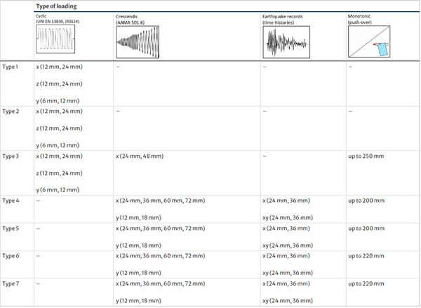
As indicated in Table 3, the following loading types were considered during the experiments:
- Cyclic Tests: According to JASS14 (1996) and UNI EN 13830 (2022), cyclic loading was considered at different drift intensity levels. To have a more comprehensive performance assessment, seismic displacements were applied separately in all directions (x horizontal and y vertical in-plane, z horizontal out-of-plane). Focusing on the x direction, these involved 10 cycles at ± 12 mm displacements (0.36% drift, considering the inter-storey height of the steel structural frame equal to 3360 mm) with a signal frequency of 0.24 Hz, and 10 cycles at ± 24 mm displacements (0.71% drift) with a signal frequency range of 0.24–0.45 Hz.
- Crescendo Tests: Following AAMA 501.6 (2001) standard, these tests involved a gradual increase in loading amplitude, reaching maximum displacement determined by the test facility's capacity, with frequencies adjusted accordingly (0.4 and 0.8 Hz).
- Earthquake Records: Far-field (Friuli 1976, Umbria-Marche 1997) and near-fault (Christchurch 2011) earthquake records were simulated through inter-story drift time series generated by non-linear numerical analysis on a multi-story reinforced concrete building (Bianchi et al. 2020). These records were scaled to achieve maximum drift amplitudes of 24 mm and 36 mm and tested in the main x-horizontal direction, as well as considering xy-combined horizontal and vertical motion (synchronized horizontal-vertical movement).
- Monotonic Tests: This test simulates a so-called pushover analysis, typically used in numerical simulation for defining the capacity of a building/component to horizontal loading. Horizontal in-plane tests were conducted until reaching a maximum displacement of 200–220 mm, due to the capacity of the testing facility. After each loading step (every 50 mm), testing was temporarily halted for visual inspection of the façade and, particularly, the silicone joint.
Table 3 Matrix of loading types (x = horizontal in-plane, y = vertical in-plane, z = horizontal out-of-plane; maximum drift amplitude levels are indicated for each direction) - Full size table
2.3 Performance indicators
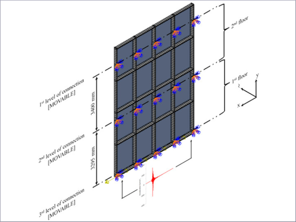
The experiments comprised a total of 140 tests. Specimens were mounted on a two-story steel support structure with a central seismic beam capable of horizontal in-plane displacements of maximum ± 75 mm and vertical displacements of maximum ± 50 mm, through a hydraulic actuator integrated with a digital controller (Bianchi et al. 2022). A comprehensive instrumentation layout was devised for each configuration to capture both in-plane and out-of-plane movements (e.g., Fig. 3a).
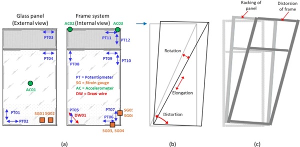
This setup included more than 30 displacement sensors, such as potentiometers and linear transducers with strokes of 50 mm, 100 mm, and 200 mm, to capture displacements of glass panels and framing systems. Draw wires and laser sensors tracked frame elongations and seismic beam movements, while accelerometers measured accelerations on glass and brackets. Strain gauges (excluding Types 1–2) recorded strains on the glass and frame system. In addition to video recordings, cameras captured multiple scans and acquired repeated point clouds in specific locations on glass and silicone to be used for Digital Image Correlation.
The following quantitative performance indicators were obtained from sensor data:
- Direct measurements of horizontal and vertical displacements at the corners of the glass, along with accelerations at the center of the panels and strains on the internal glass near the setting blocks. The displacements were used to quantify the rotation of the glass panel during seismic movements.
- Direct measurements of horizontal and vertical displacements at the corners of the internal frame, along with strains at one bottom corner on both the transom and mullion, and diagonal or corner elongations through draw wires for selected units. The recorded displacements enabled the assessment of the rotation, distortion and diagonal elongation of the frame during seismic movements (Fig. 3b).
- Direct measurements of horizontal and vertical displacements at the hook-bracket connection, as well as accelerations and strain values for configurations Type 4–7.
- Direct measurements of the horizontal displacement of the seismic beam to be used for checking the applied drift amplitude (and related drift ratio) according to the testing protocol.
These performance indicators are herein used for conducting a statistical analysis, deriving conclusions and analysing trends across different units to assess the effects of the design variables on the façade seismic performance.
3 Research results
3.1 Statistical analysis of data
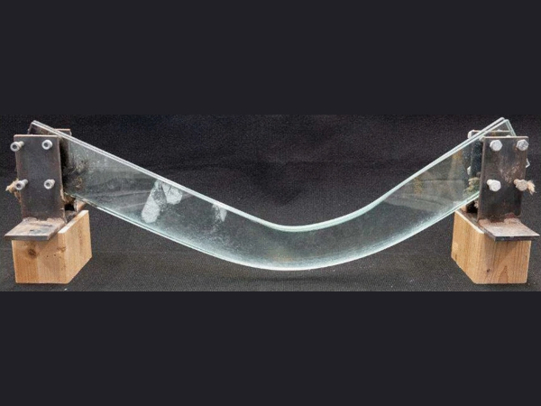
The experimental data provide a comprehensive understanding into how the facade responds to seismic loading. When the units are subject to in-plane horizontal seismic movements driven by drift amplitudes, a racking motion is triggered characterized by the rigid translation and rotation of the whole façade unit. The vertical stack joint along the transoms accommodates the resulting upward and downward differential seismic movements. As the frame begins to deform at higher drift levels, the unit leans to a rhomboidal shape (Fig. 3c), raising the risk of contact between a corner of the glass and the aluminium frame, and stress is introduced into the SSG-joints due to the inter-story drift.
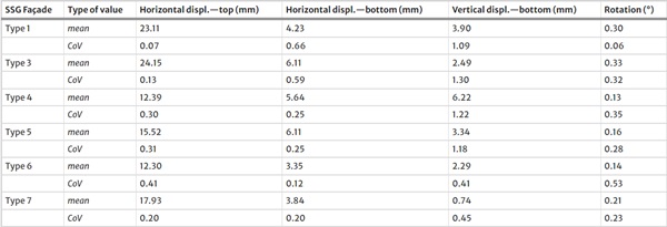
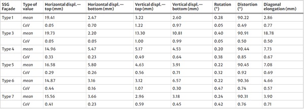
Focusing on this behaviour, a statistical analysis of the experimental results, including means, standard deviations and coefficients of variation for each intensity level (drift amplitude level), was conducted to understand the variability of seismic demand (displacement) on the non-structural component. The assessment covered only the SSG units, as the statistical analysis could not be conducted for the dry glazed system (Type 2) due to an insufficient number of tests at each shaking level (less than three). Tables 4 and 5 summarize the results (mean values and Coefficient of Variation—CoV, representing the ratio of the standard deviation to the mean value—of the maximum recorded values during the tests) for all SSG facade units for Level 1 (24mm drift amplitude). These tables present statistical data in terms of displacements at the top/bottom corners of both glass and frame, along with the corresponding rotations, distortions and diagonal elongations. Greater dispersion in data for each specimen is observed in the vertical displacement recordings, where the CoV exceeds 1, partly due to the measurements being in the order of millimeters. In contrast, the lower dispersion in the horizontal displacement recordings for Types 1 and 3 is attributed to the reduced number of data points available compared to the other façade specimens. Similarly, these results can be compared with data at higher intensity levels (Level 2, 36mm drift amplitude) for cases Type 4–7, as this intensity value was not initially considered in the test phase involving Types 1 and 3.
Table 4 Demand parameters on the glass (e.g., horizontal-x loading, 24mm) - Full size table
Table 5 Demand parameters on the frame (e.g., horizontal-x loading, 24mm) - Full size table
Comparing and further analyzing the data through regression analysis provides insights into how design parameters influence the results (Fig. 4). It is evident that the rotation of the glass increases with the glass aspect ratio, showing around a 20% increase, with high dispersion values at both lower (Level 1, 0.71% drift ratio) and higher intensity levels (Level 2, 1.00% drift ratio) (Fig. 5a, b). Conversely, the rotation decreases with the silicone aspect ratio, with a decrease of around 30% particularly prominent when moving from 1.00 aspect ratio to 2.22 aspect ratio (Fig. 5c, d), while the glass rotation is not impacted in between 2.22 and 3.00 silicone aspect ratio. When comparing rotations within the unit (Tables 2–3), it can be observed that the glass rotates less than the frame by approximately 20–35%, except for Type 1 where the high unit aspect ratio (2.71) seems to lead to a higher rocking motion of the glass on its setting blocks. The relative displacements between the two components remain within the glass/frame internal gap dimensions (8mm).
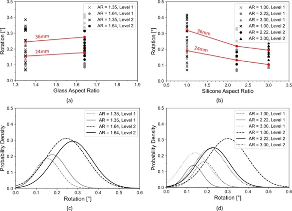
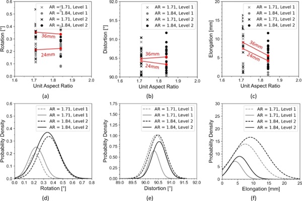
Analyzing the CoV derived from normal distributions of the data, validated through a Kolmogorov–Smirnov (KS) test for some samples, CoV values in the range of 0.2–0.5 are found for different façade types, indicating moderate to high variability. The coefficient of variation is a statistical measure of the relative dispersion of data points around the mean, and it is crucial in sensitivity analysis to identify parameters with the most significant impact on the output. In this case, the impact of the silicone aspect ratio appears to be higher than that of glass dimensions.
Focusing on the frame responses, the results indicate that values (Table 5) exhibit less dispersion when comparing different facade types. Higher rotation/distortion and diagonal elongation are associated with larger panels having a 1.35 aspect ratio. Figure 5 shows that there is no clear trend for the frame rotation and distortion, with both slightly increasing or decreasing, with a large dispersion in the outcomes. This variability persists even when considering the same loading type (e.g., only time-history analysis), especially for distortion, where the intensity of variation is very small. In contrast, a linear trend is evident for the elongation value, highlighting a decrease of around 40%) with the increase in unit aspect ratio. Examining the CoV, values fall in the range of 0.3–0.5 for rotation, 0.7–0.9 for distortion and 0.6–0.7 for elongation, indicating high relative variability. For distortion and elongation values, this indicates that the standard deviation is relatively large compared to the mean, implying a wide dispersion of data points relative to the mean. Therefore, the variation of unit dimensions significantly affects these parameters.
When analyzing the strain gauge recordings, a similar statistical analysis can be conducted to assess strain values. However, this analysis could only be performed for certain units, primarily in the last experimental phase (Type 4–7), where strains where recorded at specific locations. By assuming reference strength values of 40 MPa, 160 MPa and 355 MPa for the glass, aluminum frame and steel brackets, respectively, utilization factors were derived by converting strains (ε, recorded from strain gauges) into stresses (σ=𝐸∙ε, with 𝐸 Young's modulus of glass/frame at 70 GPa and steel at 210 GPa). For the two drift intensities used for comparison across units (24 mm, 3 6mm), the results indicated that both the glass and frame had utilization factors of less than 10%, with higher values observed for configurations (Worst Case) with limited displacement capacities of the frame. Utilization factors for the bracket system reached maximum values of 26%, indicating higher sensitivity to peak seismic force and acceleration values.
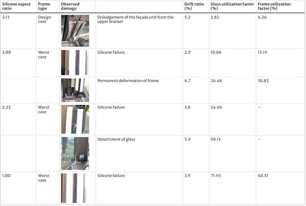
While statistical data were not available for all units, analysis of results from monotonic and dynamic tests at high levels provide insights into damage conditions within the façade systems. It was observed that the behavior of the frame system (Design vs. Worst Case) significantly influenced the outcomes. As discussed in Bianchi et al. (2024), when the frame was designed to withstand higher drift amplitudes, allowing necessary vertical movements during seismic shaking, failure primarily resulted from dislodgment of the façade from the bracket connections (Type 3). In contrast, limited displacement capacity of the frame, as simulated by fixing the bottom transom in certain configurations (Type 4, 6, 7), led to higher stress on the silicone and potential damage. Upon cracking, the façade maintained its integrity and withstood additional shaking before reaching failure due to glass detachment at higher drift ratios. However, these drift values significantly exceed the code-compliant drift values typically used to evaluate the safety of facades, which typically range around 1.00% according to the experimental procedure outlined in JASS14 (1996). Additionally, it is important to highlight that while the silicone joints failed, it did not lead to a catastrophic failure of the unit, suggesting that overall safety was not compromised.
The utilization factors at failure for all analyzed specimens (Table 6) show that the glass utilization factors increase with reduced silicone aspect ratio, indicating a higher probability of glass fracture, though the maximum recorded value was around 72%. Similarly, the frame's utilization values decreases with the increase of silicone aspect ratio. The lowest silicone aspect ratio (1.00) also indicated a potential shift in hierarchy of failure mechanisms, with the frame exhibiting lower utilization than the glass. The observed silicone failure occurred at the same drift level for configurations subjected to monotonic loading (with silicone aspect ratios of 2.22 and 1.00). However, in the case of Type 6 (with a silicone aspect ratio of 3.00), failure occurred at a lower drift level (2.9%) due to the application of a time history with a maximum amplitude of 100mm. This underscores the potential significant influence of dynamic effects on these damage states.
Table 6 Utilization factors on glass and frame at failure - Full size table
3.2 Further investigations
This section presents an overview of other findings derived from the data analysis, focusing on the behaviour of the facade in different seismic directions (out-of-plane OOP horizontal and in-plane IP vertical), the comparison between dry and wet configurations and the influence of loading type.
Experiments conducted on Types 1–3 allow for a direct comparison of façade response in all orthogonal (x, y, z) directions. Vertical motion (y) induces distortion in the unit, leading to higher elongation and distortion of the frame compared to other loading types (Table 7). For instance, elongations up to 20mm are observed under a 12 mm vertical load, which is 5–6 times higher than those resulting from horizontal loading, despite vertical loading having approximately half the maximum intensity of horizontal inputs. Distortion is particularly pronounced, with frame corner increments exceeding one degree, representing a 7–8 times increase compared to in-plane horizontal motion. Regarding the OOP drift, this is accommodated by the unit rotation at the hinge connections of the brackets, with no displacement imposed to the SSG-joints by such movement. Rotation values for both glass and frame are 2 times higher than those observed during IP loading, with glass rotation surpassing that of the frame due to a higher rocking behaviour of the glass panels on setting blocks.
Table 7 Performance indicators for different loading conditions for Type1 unit - Full size table
The obtained results also provide insights into the behaviour of dry vs. wet facade units, specifically considering Types 2 and 3, which share the same dimensions. Type 3 was indeed designed to replicate an SSG configuration equivalent to Type 2. In general, SSG systems typically exhibit superior performance compared to other glazing systems. Fragility data collected from experimental testing supports this statement, as they show that SSG solutions can withstand higher seismic demands before reaching the same level of damage as dry glazed systems (Memari et al. 2011; O’Brien et al. 2012). One key advantage of SSG systems lies in their ability to minimize glass-to-metal contact during lateral displacements. Moreover, SSG systems, particularly when using laminated glass, can retain broken glass and maintain structural joint integrity.
Analysing the sensor data and further elaborations on rotations, distortions and elongations reveal that the SSG unit exhibits higher rotation compared to the dry unit (Fig. 6). This can be attributed to the flexible silicone joints in SSG systems and different distribution of seismic forces within the system, which allow for greater movement compared to the more rigid connections typically found in dry glazed systems, such as mechanical fixings such as gaskets or pressure plates. The flexibility in SSG connections results in increased distortion and diagonal elongation of the frame, which could lead to permanent deformations at higher levels of displacement.

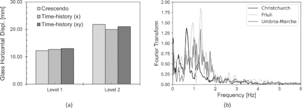
When comparing results from different dynamic loading types (Crescendo vs. Time-history), it is found that the maximum recorded displacement values across various sensors remain consistent at different intensity levels. For instance, in Fig. 7a, horizontal displacements on the glass for Type 4 façade exhibit similar values, with combined xy displacements higher than single x inputs, especially in the vertical direction. The primary distinction in dynamic inputs is observed in the time history responses when analyzing the three signals (Fig. 7b). This is due to the different properties of the seismic records, with the near-field earthquake (Christchurch) characterized by higher acceleration and limited frequencies compared to far-field earthquakes (Friuli and Umbria-Marche) which exhibit higher frequencies. This difference in frequencies is evident in the Fourier transform, which illustrates the frequency content of the signals experienced on the seismic beam during testing. Across all different earthquakes, the maximum amplitude is observed between 0.75 and 1.5 Hz. However, to investigate the record-to-record variability and its impact on the façade system, additional studies on a larger number of signals are needed (Mattei and Bedon 2021). This could be achieved through properly calibrated numerical modeling of the tested specimens.
4 Conclusions
This paper presented the key findings from an extensive experimental campaign, conducted at the Permasteelisa laboratory, to study the seismic response of unitized glazed curtain walls. Considering both quasi-static and dynamic loading conditions, different design variations were tested, including variations in unit, glass and joint aspect ratios, and framing systems with limited to high displacement capacities. This study has focused on a statistical analysis to quantify parameters such as glass and unit rotations, frame elongations and distortions, and utilization factors across different intensity levels. This analysis offers insights into the behaviour of the tested unitized curtain walls, which may be summarised as follows:
- Glass rotation increases with its aspect ratio and decreases with increasing silicone aspect ratio. The glass rotates less than the frame except for cases with high unit aspect ratios, displaying moderate to high variability in response across different façade types. Silicone aspect ratio has a higher influence on performance than glass dimensions. Variations in unit dimensions significantly affect rotations, elongations and distortions of frame.
- Strain gauge analysis reveals low utilization factors for glass and frame. Failure mechanisms vary between designs, with dislodgment of the facade from bracket connections observed in configurations designed for higher drift amplitudes. Silicone failure may be the dominating damage mechanisms in designs having limited frame displacement capacity, however at drift levels (3% or higher) which are above standard requirements. Utilization factors at failure highlight the influence of silicone aspect ratio on glass and silicone behaviour, with dynamic effects potentially affecting failure thresholds. Specifically, time history loading resulted in the same damage condition, i.e., silicone failure, occurring at a lower drift ratio (2.9%, still high compared to standard requirements) than monotonic loading for a façade with a higher silicone aspect ratio (3.00 vs. 1.00).
- Vertical movement induces significant distortion in the unit, resulting in notably higher elongation and distortion of the frame compared to other loading types. Out-of-plane drift is accommodated by unit rotation at hinge connections of the brackets, with glass and frame rotation values twice as high than those observed during in-plane loading.
- SSG units demonstrate higher rotation compared to dry units due to the presence of flexible silicone joints. The silicone joints in SSG systems therefore allow for greater deformations without affecting the glass, but this leads to higher distortion and diagonal elongation of the frame at higher displacement values.
- Recorded displacement values across various sensors remain consistent at different intensity levels when comparing results from different dynamic loading (Crescendo vs. Time-history).
- Fourier transform analysis highlights differences in response due to the dissimilar frequency characteristics between near-field and far-field earthquakes, which might differently affect the dynamic response of façades.
While this study offers preliminary insights into the correlations between façade response and design parameters, further investigations should be conducted. It is essential to compare these findings against design criteria provided by standards. Moreover, there is a need for detailed analysis of accelerations/forces, which were not covered in this paper, when compared to code-compliant floor response spectra. Additionally, deeper analyses are necessary to understand the combined effects of vertical-horizontal loading and derive the natural vibration period of the façade units. Utilizing time series analysis techniques can provide a more comprehensive understanding by analysing data collected over time and predicting responses. Furthermore, incorporating more data from measurements obtained through Digital Image Correlation would enhance the robustness of the findings in terms of strain and utilization values for the glass, including new data for the silicone itself. The proposed studies represent avenues for future research, which can refine this initial assessment and offer deeper insights into how design decisions influence facade responses.
References
Acknowledgements
This study has received funding from the European Union’s Horizon 2020 research and innovation programme under the Marie Skłodowska-Curie grant agreement No. 101029605 (H2020-MSCA-IF-2020—SAFE-FACE—Seismic SAFety and Energy efficiency: Integrated technologies and multi-criteria performance-based design for building FACadEs) for Simona Bianchi. The authors also acknowledge the valuable contribution and support provided by the Permasteelisa employees: Matteo Dazzan, Test and Lab specialist, Gianluca Casagrande, I&T specialist of the experimental measurement acquisition system and all the Test&Lab members.
Author information
Authors and Affiliations
- Delft University of Technology, Delft, The Netherlands - Simona Bianchi & Mauro Overend
- Permasteelisa Group, Vittorio Veneto, Italy - Guido Lori & Giampiero Manara
- Dow Silicones, Seneffe, Belgium - Valerie Hayez
Corresponding author
Correspondence to Simona Bianchi.
Ethics declarations
Conflict of interest
On behalf of all authors, the corresponding author states that there is no conflict of interest.

