Article Information
- Digital Object Identifier (DOI): 10.47982/cgc.9.594
- Published by Challenging Glass, on behalf of the author(s), at Stichting OpenAccess.
- Published as part of the peer-reviewed Challenging Glass Conference Proceedings, Volume 9, June 2024, 10.47982/cgc.9
- Editors: Christian Louter, Freek Bos & Jan Belis
- This work is licensed under a Creative Commons Attribution 4.0 International ( CC BY 4.0) license.
- Copyright © 2024 with the author(s)
Authors:
- Mauro Corrado - Politecnico di Torino
- Arturo Chao Correas - Politecnico di Torino
- Giulio Ventura - Politecnico di Torino
Abstract
The use of glass as structural material has highlighted the need for more reliable numerical approaches to analyze its mechanical behavior, especially in the accidental eventuality of fracture. Modelling the behavior of fractured laminated glass, in fact, is fundamental to assess the Post-Fracture load-bearing capacity. However, this is a highly challenging task because of the many interplaying factors, such as the viscoelastic and thermal-dependent behavior of the interlayer, the presence of a highly complex and variable crack pattern and the interaction among fragments. The objective of the present work is the development and testing of a robust numerical model that can naturally introduce the generated crack pattern into virtual specimens and manage the interaction among many fragments.
The phase field fracture model is herein explored, by assigning the damage variable to fit the pre-existing crack pattern. Then, the specimen is loaded letting the phase field managing the fragments interaction. The dependence of the stress tensor with the damage variable is herein defined through the Cleavage-Deviatoric model, since it prevents fully damaged regions from transmitting tensile and shear stresses yet keeping their ability to bear compressive forces. Indeed, this model can asymptotically reproduce unilateral and frictionless contact conditions between the existing crack lips. Preliminary case studies are discussed to check the potentiality of the proposed approach.
1.Introduction
Differently from the most common construction materials, such as concrete and steel, the almost perfect elastic-brittle mechanical response and the sensitivity to cracking give glass elements a high risk of breakage, which can be critical if no further measures for the situation during the event of fracture or for the situation after the event of fracture are taken. Consequently, CEN/TS 19100-1 (2021) has introduced the concept that the design of glass structures shall always consider situations where parts of or the entire glass component fractures. Such a requirement is pursued by defining two additional limit states besides the well-known serviceability and ultimate limit states, namely the Fracture Limit State (FLS) during the event of fracture, and the Post Fracture Limit State (PFLS) where glass is fractured. In the PFLS sufficient safety after fracture for a limited period of time shall be verified, by guaranteeing a residual resistance of the glass component or an alternative load path.
Laminated glass (LG) is the most suitable type of glass to meet the requirements of PFLS, since it has an intrinsic redundancy due to the presence of more than one ply, that can be exploited in case not all the plies fracture. With reference to LG, the PFLS is further split in two categories: PFLS I, when at least one ply remains intact and PFLS II, when all plies are fractured. While well-established models are now available for the analysis of intact LG panes at the Ultimate Limit State (Foraboschi, 2014; Belis et al., 2013; Biolzi et al., 2017; Galuppi and Royer-Carfagni, 2016), their counterpart for assessing the post fracture behaviour is missing, although some attempts have been made (Biolzi et al., 2019; Biolzi et al., 2020; Biolzi and Simoncelli, 2022; Bedon and Fasan, 2024). According to CEN/TS 19100, PFLS of glass components can be assessed by experimental testing or alternatively by a theoretical assessment.
However, the only way admitted to theoretically assess the residual load bearing capacity in the PFLS is to consider that at least one ply of the LG component remains unfractured (PFLS I), neglecting favourable effects of the fractured glass plies. On the one hand, this assumption must be justified, whereas, on the other hand, it may result in being too conservative. Furthermore, the case where all the plies are fractured (PFLS II), which may still provide a residual load bearing capacity, cannot be analysed. Therefore, the verification requires research and experimental testing of the original glass member including its supports, approach that most of the practitioners cannot afford, except for very simple structures. In this context, a numerical approach for evaluating the residual load bearing capacity of fractured LG panes can be beneficial for the design process.
The main challenge of quantitatively assessing the residual behaviour of shattered glass components lies in the complex interactions among fragments, which are often numerous and of contorted shapes. These characteristics necessarily call for the use of computational approaches to solve the continuum’s state throughout the fragmented domain, among which the Finite Element (FE) method stands out. However, the standard formulation of the FE method is unable to deal with the unilateral contact conditions occurring along the fragment interfaces, hence requiring its ad hoc enrichment. Given that, the conventional modelling pathway consists of the straightforward representation of the physical phenomenon, thus modelling each fragment as a separate continuum subjected to some contact pressure exerted by the neighbouring fragments to avoid penetration. Despite this procedure being well known and robust, it requires extensive and tedious pre-processing for the study of fragmented domains since the mesh must conform with each of the fragments’ geometry. Additionally, given thatthe interactions between fragments are determined via node tracking techniques, the resulting computational cost of the problem increases considerably with the number of fragments and contact surfaces.
In light of these difficulties, the present study explores the use of the well-established Phase Field fracture model (PFM) introduced by Bourdin et al. (2000) to represent the internal cracks that give rise to the different fragments, as well as to manage the interactions between them. Rooted in the variational revisitation of brittle fracture by Francfort and Marigo (1998), the PFM exploits thetheoretically robust regularization conceptualized by Ambrosio and Tortorelli (1990) to approximateany discontinuity by localized transition bands. To that end, the PFM enriches the displacementproblem with a nonlocally-driven continuous scalar field, also known as phase field or damage, that pointwise determines the state and stiffness of a material within the domain. Such a feature renders implicit the PFM representation of a crack, hence potentially allowing any crack pattern, regardless of its complexity, to be represented over a certain non-conforming mesh. Furthermore, the PFM has been reported by Vicentini et al. (2024) to be able to asymptotically reproduce unilateral contact conditions upon a proper choice of the function that modulates the stiffness based on the value of the phase field. Therefore, the PFM poses a powerful contender for assessing the residual behaviour of fractured glass components, in both PFLS I and PFLS II cases, especially when these are multiply fragmented.
2. Particularization of the Phase Field fracture model for managing contact interaction between fragments
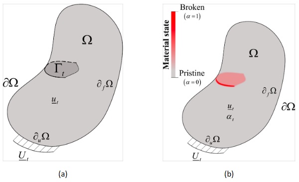
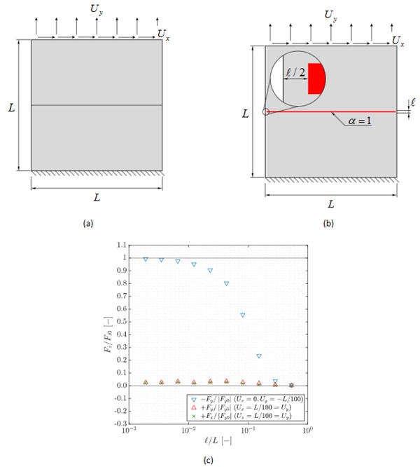
Let us consider the generic continuum problem illustrated in Fig. 1a, in which a structural domain Ω∈∼𝑁|𝑁={2,3} with external boundary 𝜕Ω∈∼𝑁−1 and outward normal 𝑛 is initially in absence of mechanical solicitations, yet it presents a set of internal cracks represented by Γ∈∼𝑁−1. These cracks cause any subsequent structural behaviour to be piecewise continuous, with numerically inconvenientsharp discontinuities potentially taking place all along Γ. Given this scenario, let us establish the corresponding PFM by first introducing a scalar (phase) field 𝛼:Ω→[0,1], so that 𝛼= 0 and 𝛼= 1represent pristine and broken material states, respectively, and the transition from one another is continuous in space. In particular, considering the problem at hand and using the AT1-PFM (Pham et al., 2011), the strong form of the principle that governs the spatial distribution of 𝛼 reads as:

where ℓ stands for the PFM’s regularization length. As seen, Eq. (1) represents a Poisson-like problemdefined in terms of Partial Differential Equations. Upon resolution, the resulting field for 𝛼 transitions continuously from 𝛼= 1 at Γ to 𝛼= 0 sufficiently far from it, as illustrated in Fig. 1b. Moreover, thesize of the region surrounding Γ in which 𝛼 takes non-zero values is governed by ℓ, so that the original “sharp” problem in Fig. 1a is recovered as ℓ→0.
Once the field 𝛼 is determined all along Ω by solving the problem in Eq. (1), the PFM can be further exploited to estimate the behaviour of the fractured domain in terms of the displacement field 𝑢:Ω→∼𝑁. To that end, let us assume that: (i) Ω is filled with a linear elastic, homogeneous and isotropic material whose Lamé constants are 𝜆 and 𝜇; and (ii) Ω is subjected to some mechanical solicitations in the form of prescribed displacements 𝑈 along 𝜕𝑢Ω and prescribed forces 𝑏 and 𝑓 distributed along Ω and 𝜕𝑓Ω=𝜕Ω\𝜕𝑢Ω, respectively. Provided that, the strong form of the corresponding quasi-static elastic problem writes as:

where σ(ε;α) represents the stress tensor associated to the infinitesimal strain tensor ε and modulated by a given α. For the sake of clarity, the semicolon separates unknown variables to its left from fixed known fields to its right. Hence, it is through the proper definition of σ(ε;α) that the PFM is able to approximate unilateral contact interactions while remaining in a continuum setup. In particular, these conditions consist in showcasing no stiffness upon both the normal separation and the tangential sliding of crack lips, whereas hard contact interactions take place to avoid the unphysical penetration of one fragment into another. To this end, it is a common practice to exploit the separation of variables to define σ(ε;α), hence resulting the following expression for the AT1-PFM:

in which 𝑘 is a small parameter used for ensuring some residual stiffness as 𝛼=1, and both 𝜎𝐷 and σR represent the damageable and residual parts of the stress tensor. In particular, the so-called Cleavage-Deviatoric model proposed by Amor et al. (2009) was reported by Vicentini et al. (2024) to be able to exactly reproduce the behavior above mentioned as ℓ→0. In particular, this model defines the damageable and residual parts of the stress tensor as:

and:

where I represents the identity tensor and •± =(•±|•|)/2.
3. Implementation of the approach and case study on the effect of 𝓵 on the residual performance of simply fractured domains
At this point, it is evident that the PFM-based approach for assessing the load-bearing capacity of fractured glass structures exploits the ability of the Cleavage-Deviatoric model to reproduce unilateral contact conditions between crack lips while remaining in a continuum context. Nonetheless, this formulation only performs exactly as desired in the limit ℓ→0, so that the finite value of ℓ in actual implementations involves some degree of approximation to the actual behaviour. It is therefore paramount for the robustness of the approach to properly understand the potentially distorting effect that using finite values of ℓ has on the resultant behaviour, as well as to establish some practical guidelines for the model setup.
In this sense, the present section reports the results of a simple case study that depicts the effect that varying the magnitude of ℓ has on the resultant crack lip interaction. To that end, the scenario illustrated in Fig. 2a is considered, this consisting of a squared domain of dimensions 𝐿𝑥𝐿 in which: (i) plane strain conditions take place; (ii) the bottom edge is clamped so that 𝑢𝑥=𝑢𝑦= 0 therein; (iii) the top edge has some prescribed displacements per 𝑢𝑥=𝑈𝑥 and 𝑢𝑦=𝑈𝑦; (iv) both the right and left edges are free; and (v) the domain presents an horizontal crack Γ along its midplane. Thereafter, the resultant crack lip interactions can be globally assessed by determining the resultant reaction forcesper unit thickness 𝐹𝑥 and 𝐹𝑦 arising from the imposition of different combinations of 𝑈𝑥, 𝑈𝑦 and ℓ. In particular, two loading cases are to be considered hereafter, one of uniaxial compression (𝑈𝑥= 0, 𝑈𝑦=−𝐿/100) and one of combined traction and shear (𝑈𝑥=𝑈𝑦=𝐿/100): the former allows for assessing the non-interpenetration across the crack, while the latter shows the absence of stiffness under such loading conditions.
The implementation of this setup to a Finite Element (FE) context is conducted using the open source Python library FEniCSx (Alnæs et al., 2015). The discretization of the domain is undertaken by first order triangular elements whose characteristic size is 𝐿/100 everywhere but in the surroundings of the crack, whereof its size is refined down tomin (ℓ/4,𝐿/100). Per the characteristics of FE modelling, the successful implementation of the here described PFM-based approach requires addressing some of the theoretical aspects described in the previous section with flexibility, especially in what concerns the Dirichlet boundary conditions for 𝛼𝛼. Ideally, these are imposed over the (𝑁−1)-dimensional locus of points Γ, but this is not convenient in practice for it would require using meshes that are conforming with Γ. Now switching the attention to the mechanical problem, the localized stiffness reduction due to 𝛼 is determined element-wise, so that in order to obtain the desired behaviour it is required that there exists fully damaged elements in the surroundings of Γ. These difficulties are adverted by setting 𝛼= 1 condition all throughout an 𝑁𝑁-dimensional locus of points ΩΓ, which consist in a stripe of thickness ℓ that surrounds Γ (see Fig. 2b), hence ensuring fully damaged elements therein. On the downside, this approximation can lead to some instabilities when ΩΓ meets free edges due to the localized lack of stiffness. To avoid this, a buffer zone of width ℓ/2 in between ΩΓ and the free edges is introduced (see Fig. 1b), so that 𝛼𝛼 is not imposed to be equal to 1 therein but let to diffuse freely per Eq. (1), thereby retaining some localized stiffness. Overall, these deviations from the original problem are still coherent with the regularization nature of the PFM since the original sharp discontinuity problem is still recovered in the limit ℓ→0.
Provided this, the case study is the conducted by setting the Young’s modulus 𝐸=72 GPa and the Poisson’s ratio 𝜈= 0.2. For each of the two aforementioned loading conditions, ten different values of ℓ/𝐿 are considered within the range from (ℓ/𝐿)~10⁻³ to (ℓ/𝐿)~10⁰, and the corresponding reaction forces per unit thickness 𝐹𝑥 and 𝐹𝑦 along the upper edge are determined and reported in Fig. 2c. It is to be noted that these results are normalized by the reaction forces 𝐹𝑥0 and 𝐹𝑦0 showcased by pristine domains subjected to the corresponding loading conditions. Particularly, for 𝑈𝑥= 0 and 𝑈𝑦=−𝐿/100, 𝐹𝑥0 is null whereas 𝐹𝑦0 is:

which also coincides in absolute value with the 𝐹𝑦0 obtained when 𝑈𝑥=𝑈𝑦=𝐿/100. In this latter case, 𝐹𝑥0 turns out:

Therefore, it is clear after Fig. 2c that the PFM-based approach is indeed capable of accurately reproducing unilateral contact conditions once ℓ/𝐿≪1 since: the compressive stiffness across the crack is virtually identical as if no crack was present, i.e. 𝐹𝑦≈𝐹𝑦₀ for 𝑈𝑦<0, whereas the shear and tensile stiffness across the crack are negligible in comparison with the pristine performance.
4. Mechanical modelling of monolayer glass panes with real crack patterns
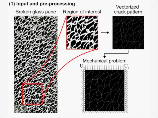
Once it is proven that the above-described PFM-based approach is able to accurately reproduce the mechanical interaction between simply shaped fragments, it is now to be shown how it can be exploited to assess the residual mechanical performance of actual fractured glass components. For the sake of clarity, the logical workflow behind this approach is illustrated in Fig. 3. In this regard, the procedure begins with the image of an actual fragmented glass pane with arbitrarily complex cracks shapes, from which the region of interest of dimension 𝐿 x 𝐿 is isolated. Therein, the combination of a black background, indirect white lighting and the optical property of glass leads to the cracked and pristine regions being easily discernible for they appear as white and black in colour, respectively. However, and despite such an image is visually descriptive of the actual crack pattern, it still contains many superfluous and disruptive features that render it unsuitable for straightforward use towards the PFM definition, e.g. the apparent thickness of cracks caused by the camera misalignment.
Therefore, some image pre-processing is required before it can be used for constructing the numerical model. Herein, the image of the region of interest is rendered useful by exploiting vector graphics software to determine an approximate vectorized description of the complex cracks in terms of piecewise-defined Bezier curves. This technique therefore allows to obtain a “clean” approximation of the image in which the crack patterns are unequivocally defined by the mathematical description of its shape. Likewise, given that vector graphics software commonly allows to define the thickness of the Bezier curves at will, it becomes straightforward to use this vectorized representation of the cracks to define ΩΓ within the modelled domain Ω (see Section 3). Eventually, combining the outcome of this pre-processing procedure with the specific set of mechanical loadings results in the complete definition of the problem that is to be solved by the PFM-based approach.
The information resulting from the input pre-processing is then used to define the Phase Field problem in the FE context. To that end, the vectorized definition of the cracks is first decoded into a binary distribution of α throughout the mesh, which only takes nodal values equal to either 0 or 1. Then, Boolean operations are used to determine the nodes in which α= 1, from which an implicit definition of ΩΓ within the discretized domain is obtained. This information is then passed to the numerical FE solver associated to the problem defined per Eq. (1) so as to properly impose the Dirichlet boundary conditions on α. Upon resolution, the continuously defined field α is obtained, portraying a discretized and approximated PFM representation of the crack pattern. Once α is determined, all ingredients needed for solving the mechanical problem defined in Eq. (2) are available. In this regard, the corresponding mechanical solver is provided with the α field, the Dirichlet boundary conditions on 𝑢, and any distributed mechanical loading f and 𝑏𝑏 that applies. Based on this, the obtention of the displacement field 𝑢 is straightforward, with different magnitudes of interest such as strains, stresses or reaction forces then being determined through postprocessing.
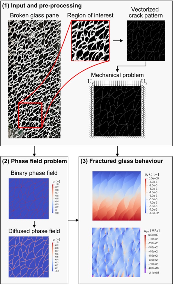
Looking at the particular analysis described in Fig. 3, it represents a confined compression test of the fractured domain. Assuming 𝐸=72 GPa, 𝜈= 0.2, ℓ/𝐿= 3.1667∙10⁻³ and 𝑓=𝑏= 0, a pristine domain under the same loading conditions would reveal an overall stiffness of |𝐹𝑦₀|/𝑈𝑦𝐸 ≈1. 1111, as opposed to the value of |𝐹𝑦|/𝑈𝑦𝐸 ≈0. 7778 showcased by the considered fractured domain. Likewise, provided a prescribed vertical displacement that is compressive and of magnitude 𝐿/100, the vertical stress in the pristine domain would be 𝜎𝑦𝑦,₀=−800 MPa, whereas in the broken domain one can find localized negative values for 𝜎𝑦𝑦 of magnitude as high as 𝜎𝑦𝑦,₀=−2100 MPa. Overall, the PFM-based approach depicted in Fig. 3 shows promise for the assessment of the mechanical behaviour of real-world fractured glass components, although further quantitative validation of the results is required.
5. Preliminary study on the post-fracture expansion in laminated tempered glass
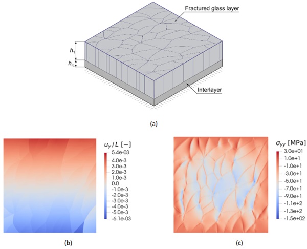
The herein introduced PFM-based approach can also be exploited to study the residual performance of laminated glass structures. In this regard, the present section will provide some insights into the preliminary modelling of the post-fracture in-plane expansion occuring in laminated tempered glass (Nielsen et al., 2022). For the sake of simplicity, the setup illustrated in Fig. 4a will be here considered. In particular, this consists in a fragmented glass pane of dimension 𝐿𝑥𝐿 and thickness ℎ₁ that presents the same fragmentation pattern as the one studied in Section 4 and is assumed to present a constant deformation state through the thickness. Besides this, this layer is adhered on one side to a cohesive interlayer of thickness ℎ𝑖nt which only presents shear stiffness of modulus 𝜇𝑖nt and is in turn adhered to an infinitely rigid component on the opposite interface. Therefore, even in the absence of restricted displacements along the glass pane’s boundary, the domain does not deform freely.
Given this setup, the post-fracture expansion is preliminarily modelled by assuming the glass pane to undergo a deformation per ε₀ in the absence of further mechanical solicitations. Therefore, the strong form of the glass pane’s elastic problem now writes as:

which represents the corresponding extension of the baseline elastic problem introduced in Eq. (2). Remarkably, the presence of a cohesive term in the problem above introduces a certain size effect in the problem in that, upon scaling the problem by 𝐿, the normalized solution remains constant only if the ratio 𝜇𝑖nt/𝐿 is maintained.
At this point, let us resolve the problem defined in Eq. (8) by taking the solution for 𝛼 from the previous section and assuming that the domain boundary has no imposed displacements, i.e. 𝜕𝑢Ω=∅, and thatthe relaxation straining ε₀ is homogeneous and equal to:

so that the material attempts to expand the same any in plane direction. Additionally, the different material properties and modelling parameters are here set as Assuming 𝐸=72 GPa, 𝜈= 0.2, ℓ/𝐿=3. 1667∙10⁻³ and ℎ₁/𝐿= 0.1, ℎ𝑖nt/𝐿= 0.01, 𝜇𝑖nt/𝐿=50 MPa/mm, which for instance yields in the results for 𝑢𝑦/𝐿 and 𝜎𝑦𝑦 reported in Fig. 4b and 4c, respectively. Therein, it results clear how the central fragments are the ones that retain the most compressive stresses, this arising from the cumulative confinement effect caused by the cohesive layer opposing the displacement of the different. As for this, despite the outmost fragments showcasing the highest displacements inmagnitude, they turn out to be mostly stress-free since they are subjected to such a confinement to a lesser extent.
6. Conclusions
Overall, the PFM-based approach here introduced has proved suitable for modelling the behavior of fractured glass structures that interact with other conventional structural components, such as a cohesive interlayer. Nonetheless, these results are only preliminary and they require further validation and study. Likewise, despite its convenience and theoretical robustness, the herein proposed PFM-based approach also showed some convergence-related difficulties while solving the problem in Eq. (8) upon certain combinations of 𝜇𝑖nt/𝐿. As such, further study in this regard is required to ascertain the robustness of the proposed approach for the preliminary study of partially fractured laminated structures.
Acknowledgements
This project has received funding from the European Union’s Horizon 2020 research and innovation programme under the Marie Skłodowska Curie grant agreement No 861061
References
Alnæs, M.S., Blechta, J., Hake, J., Johansson, A., Kehlet, B., Logg, A., Richardson, C., Ring, J., Rognes, E., Wells, G.N.: The FEniCS Project Version 1.5. Arch. Numer. Softw. (2015). https://doi.org/https://doi.org/10.11588/ans.2015.100.20553
Ambrosio, L., Tortorelli, V.M.: Approximation of functional depending on jumps by elliptic functional via t-convergence. Commun. Pure Appl. Math. (1990). https://doi.org/10.1002/cpa.3160430805
Amor, H., Marigo, J.-J., Maurini, C.: Regularized formulation of the variational brittle fracture with unilateral contact: Numerical experiments. J. Mech. Phys. Solids (2009). https://doi.org/10.1016/j.jmps.2009.04.011
Bedon, C., Fasan, M.: Post-Fracture Stiffness and Residual Capacity Assessment of Film-Retrofitted Monolithic Glass Elements by Frequency Change. Math. Probl. Eng.(2024). https://doi.org/10.1155/2024/8922303
Belis, J., Bedon, C., Louter, C., Amadio, C., Impe, R.V.: Experimental and analytical assessment of lateral torsional buckling of laminated glass beams. Eng. Struct. (2013). https://doi.org/10.1016/j.engstruct.2013.02.002
Biolzi, L., Casolo, S., Diana, V., Sanjust, C.A.: Estimating laminated glass beam strength via stochastic Rigid Body-Spring Model. Compos. Struct. (2017). https://doi.org/10.1016/j.compstruct.2017.03.062
Biolzi, L., Casolo, S., Orlando, M., Tateo, V.: Modelling the response of a laminated tempered glass for different configurations of damage by a rigid body spring model. Eng. Fract. Mech. (2019). https://doi.org/10.1016/j.engfracmech.2019.106596
Biolzi, L., Simoncelli, M.: Overall response of 2-ply laminated glass plates under out-of -plane loading, Eng. Struct. (2022). https://doi.org/10.1016/j.engstruct.2022.113967
Biolzi, L., Cattaneo, S., Orlando, M., Piscitelli, L.R., Spinelli, P.: Constitutive relationships of different interlayer materials for laminated Glass, Compos. Struct. (2020). https://doi.org/10.1016/j.compstruct.2020.112221
Bourdin, B., Francfort, G.A., Marigo, J.-J.: Numerical experiments in revisited brittle fracture. J. Mech. Phys. Solids (2000). https://doi.org/10.1016/S0022-5096(99)00028-9 CEN/TS 19100-1:2021 Design of glass structures - Part 1: Basis of design and materials. European Committee for Standardization, Brussels (2021). Foraboschi, P.: Optimal design of glass plates loaded transversally. Mater. Des. (2014). https://doi.org/10.1016/j.matdes.2014.05.030
Francfort, G.A., Marigo, J.-J.: Revisiting brittle fracture as an energy minimization problem. J. Mech. Phys. Solids (1998). https://doi.org/10.1016/S0022-5096(98)00034-9
Galuppi, L., Manara, G., Royer-Carfagni, G.: Practical expression for the design of laminated glass. Compos. Part B-Eng.(2013). https://doi.org/10.1016/j.compositesb.2012.09.073
Galuppi, L., Royer-Carfagni, G.: A homogenized model for the post-breakage tensile behavior of laminated glass. Compos. Struct. (2016). https://doi.org/10.1016/j.compstruct.2016.07.052
Nielsen, J.H., Schneider, J., Kraus, M.A.: The in-plane expansion of fractured thermally pre-stressed glass panes: -An equivalent temperature difference model for engineering glass design. Constr Build Mater (2022). https://doi.org/10.1016/j.conbuildmat.2022.126849
Pham, K., Amor, H., Marigo, J.-J., Maurini, C.: Gradient Damage Models and Their Use to Approximate Brittle Fracture. Int. J. Damage Mech. (2011). https://doi.org/10.1177/1056789510386852
Vicentini, F., Zolesi, C., Carrara, P., Maurini, C., De Lorenzis, L.: On the energy decomposition in variational phase-field models for brittle fracture under multi-axial stress states. Int. J. Fract. (2024). https://doi.org/10.1007/s10704-024-00763-w

