Article Information
- Digital Object Identifier (DOI): 10.47982/cgc.9.542
- Published by Challenging Glass, on behalf of the author(s), at Stichting OpenAccess.
- Published as part of the peer-reviewed Challenging Glass Conference Proceedings, Volume 9, June 2024, 10.47982/cgc.9
- Editors: Christian Louter, Freek Bos & Jan Belis
- This work is licensed under a Creative Commons Attribution 4.0 International (CC BY 4.0) license.
- Copyright © 2024 with the author(s)
Authors:
- Mirko Pejatovic - Ghent University, Department of Structural Engineering and Building Materials
- Robby Caspeele - Ghent University, Department of Structural Engineering and Building Materials
- Jan Belis - Ghent University, Department of Structural Engineering and Building Materials
Abstract
In contemporary architecture, there is a growing emphasis on structural transparency, often leading to the consideration of design solutions that incorporate complete structural systems made from materials such as structural glass. While glass is typically fragile and exhibits elastic deformations under normal loads during its service life, unforeseen events can cause glass breakage. Load redistribution requirements at the member and system level can be crucial in preventing potential structural collapse. A new method for connecting beam components was developed in (Martens, 2018), with a focus on ensuring structural safety for both individual components and the overall system. This method improves transparency and preserves a seamless visual appearance of the statically indeterminate beam through the utilization of Cast-In-Place (CIP) bonding technology. CIP bonding technology permits on-site lamination, offering a solution for installing large laminated glass components in locations challenging to be reached and accommodating sizes that exceed the dimensions of standard production and transportation capabilities.
This paper places particular emphasis on the numerical study of the in-plane behaviour of a novel steel reinforced glass frame prototype conceived to be (partly) constructed using UV-curable beam-column connections. For that purpose, a series of non-linear 3D Finite Element (FE) simulations is performed in Abaqus. Specified interlayer properties used in the simulations relate to SentryGlas®, which is used for beams and columns, whereas UV-curable resin is used for beam-column connections. Sensitivity analyses are performed assuming various stiffnesses of the UV-curable resin. The numerically simulated behaviour of the novel frame prototype is compared to the experimental results of an equivalent simply supported beam. The results indicate that the effect of the considered beam-column connections can significantly enhance the load-carrying capacity of the steel-reinforced glass frame system.
1.Introduction
Overcoming challenges related to dimensions, production, and transportation of glass pieces is crucial for constructing large structures built in structural glass. The continuity of reinforcement, which can be bonded to glass to provide post-fracture capacity (Martens et al., 2016), represents an additional challenge towards the safety of such structures. A new modular system approach to connecting steel-reinforced beam components into a continuous beam system was introduced as a solution to those challenges, emphasizing transparency and structural safety at individual component and system level (Martens, 2018). This method utilizes in-situ welding of steel reinforcement and Cast-In-Place (CIP) bonding technology to enhance transparency and maintain a seamless visual appearance of laminated glass beams. CIP bonding technology facilitates on-site lamination, crucial for installing large laminated glass components in challenging or inaccessible locations. Different variations of CIP connections and their mechanical performances have been investigated in the literature (Martens, 2018); (Volakos et al., 2021, 2023).
To provide additional load-carrying capacity to portal frames, beam-column connections need to possess a certain rotational stiffness and strength. Various solutions for moment-resistant beam-column joints have been explored in literature (Belis et al., 2009; Huang, 2017; Pejatovic et al., 2022; Prautzsch & Weller, 2016; Snijder et al., 2014; Weller et al., 2010). However, the literature lacks comprehensive studies of the stiffness, strength and ductility performance of such connections, as well as numerical and analytical prediction models. The previously described innovative concept can be extended to two-dimensional structures, such as portal frames, where the robustness can be achieved through a similar construction technique at locations of beam-column joints. In previous work, the authors of this paper have explored the rotational characteristics of a beam-column connection prototype reinforced with steel bars (see (Pejatović et al., 2024)), addressing the effect of the lamination technology on the rotational characteristics of the connection prototype. It was concluded that the connection realized through the CIP technique can achieve a substantial post-fracture and rotational capacity when designed with a well-balanced combination of structural and material parameters.
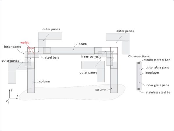
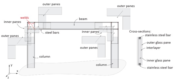
The current paper numerically investigates the effect of the CIP beam-column connections on the in-plane behaviour of a novel steel-reinforced frame prototype, as illustrated in Fig. 1. The frame can be built using welding of reinforcing steel and a combination of autoclave-laminated and cast-in-place (CIP) lamination technique. In this concept, the frame consists of a reinforced beam and columns, which are laminated in the autoclave process by e.g. SentryGlas® interlayer. The beam and columns are transported to the construction site and there connected by welding of the reinforcing bars and additional glass panes bonded by CIP lamination. It should be noted that the welds need to be realizedsufficiently distant from the glass to prevent potential thermal fractures caused by local heat in the heat-affected zone. The length of this zone has been chosen to be equal to the height of the beam.
To validate the results of these simulations, a testing program will be conducted by the authors in the future.
2. Numerical study
2.1. Finite element (FE) model
To numerically simulate the in-plane behaviour of the frame prototype under a vertical force, a 3D FEmodel was created in Abaqus (Abaqus/CAE User’s Guide). The view on the outer and inner panes with the reinforcement is illustrated in Fig. 2(a)-Fig. 2(b), respectively, with the dimensions, the cross-section, indications about the elements of the frame (beam, column and connections) and glass interruptions. Due to symmetry, only a half of the frame is modelled. The frame is subjected to a vertical imposed displacement (δ) in the middle of the beam, in a displacement-control simulation, and an equivalent force (F) is obtained from the reactions at the bottom of the columns, where the frame is vertically restrained by pinned boundary conditions. The frame is additionally laterally supported against buckling. In real structures, the frame is typically laterally supported by façade and roof panels.
Table 1 summarizes material models and specified material properties used in this numerical study. Glass is considered as a linear-elastic material with a possibility of cracking, which is modelled by the reducing element approach (REA). This model assumes that after the principal tensile strain (ε1) in a finite element exceeds a prescribed value (ε1,cr= fgt / Eg = 45/70000 = 0.64 ‰), the element cracks, after which it loses strength and stiffness. For more information on this model one can refer to (Pejatovic et al., 2022). Reinforcing steel is modelled as an elastic-plastic material with a yield strength of 680 MPa and tensile strength of 840 MPa, on the basis of uniaxial tensile tests on steel bars with dimensions 10 x 10 mm, reported in (Pejatović et al., 2024). Welds are conceived in the form of full tee and corner joints. Such welded sections possess strength equal to or greater than that of the original sections, ensuring the full plastic capacity of the bars can be utilized without risk of failure at the welds. SentryGlas® in the beam and columns, and UV-curable interlayer in the connections, are modelled using linear-elastic material behaviour, as a simplification. To investigate the effect of different stiffnesses of the UV-curable interlayer, the elastic modulus of Eint,UV = 10 MPa, 50 MPa and 100 MPa is assumed. The interface between all the materials is modelled assuming perfect bond.
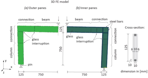
Table 1: Material models and specified material properties used in the numerical study based on (Callewaert et al., 2012)(Pejatovic et al., 2022);(Pejatović et al., 2024)).

2.2. Numerical results
Normalized numerical force-displacement (F - δ) curves for different stiffnesses of the UV-curable resin (Eint,UV)at the location of beam-column connections are presented in Fig. 3. The curves are normalized by the failure force (Fu,3PBT) and the corresponding displacement (δu,3PBT) from the 3-point bending test from the equivalent bending test on the simply supported beam with similar dimensions and mechanical properties of the materials (for more details about this test one can refer to (Martens, 2018)). Firstly, one can observe a good agreement between the numerical and tested behaviour for the simply supported beam, represented by the solid and dashed red lines, respectively. This means that the REA can be successfully used to simulate the post-fracture performance of such type of structures. On that basis, frames with different Eint,UV are simulated and the corresponding curves are plotted in grey lines. One can notice that the initial slope, the force at first crack and at failure in the case of frames increase with larger Eint,UV compared to the case of a simply supported beam. The larger Eint,UV provides better interaction between steel reinforcing bars and glass panes at the location of the beam-column connections, providing the connection with the larger rotational stiffness and a certain strength, hence increasing the load-carrying capacity of the considered frames (at least 50 % compared to the equivalent beam), as reported in Fig. 3.
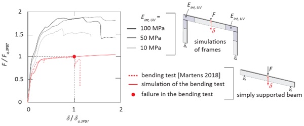
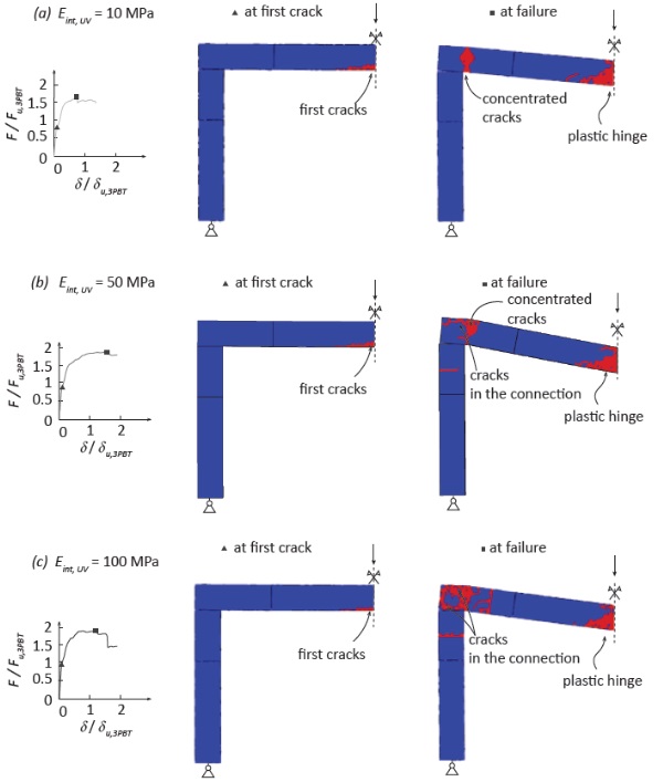
Fig. 4(a)-Fig. 4(c) respectively depict damage patterns in the outer glass panes (cracked elements are represented by red colour) for the considered stiffnesses of the UV-curable interlayer. In all the cases, first cracks occurred in the mid-span of the beam. Regarding the failure of the frame, one can observe that the plastic hinge obtained in the middle of the beam is followed by a more pronounced damage pattern at the location of the connection for the larger stiffness. The stiffer interlayer transfers higher stresses from steel to glass, whereas a more flexible interlayer has a limited stress transmission capability. In particular, Fig. 4(c) indicates that the failure mode of the frame for the stiffer interlayer is crushing of the glass in the beam-column connection, due to the excessive concentration of deformations. On the other hand, Fig. 4(a) suggests limited damages in the glass connection due tothe lower stiffness of the interlayer.
3. Conclusions
This paper presents a numerical study of the in-plane behaviour of a novel steel-reinforced glass frame prototype with UV-curable beam-column connections. A connection methodology emphasizing structural safety and enhanced transparency with steel welding and Cast-In-Place (CIP) bonding philosophy was used for the beam-column as a technique that may facilitate on-site lamination, addressing challenges in installing large laminated glass components. To numerically simulate the in-plane behaviour of the frame prototype under a vertical force, a 3D FE model was created in Abaqus. To account for cracking in glass, the reducing element approach (REA) was used. To investigate the effect of different stiffnesses of the UV-curable interlayer, an elastic modulus Eint,UV of 10 MPa, 50 MPa and 100 MPa is assumed. Based on the obtained results, the following conclusions can be made:
- The simulated prototype's behaviour indicates a significant enhancement in load-carrying capacitycompared to the tested equivalent simply supported beam for any stiffness of the UV-curable interlayer. The larger Eint,UV provides better interaction between steel reinforcing bars and glass panes at the location of the beam-column connections, providing the connection with the larger rotational stiffness and a certain strength, hence increasing the load-carrying capacity of the considered frames (at least 50 % compared to the equivalent beam)
- The initial slope, the force at first crack and at failure in the case of frames increase with larger stiffness of the UV-curable interlayer;
- Regarding the failure mode of the frame, it was found that the plastic hinge obtained in the middle of the beam is followed by a much more pronounced damage pattern at the location of the connection in the case of a larger stiffness of the UV-curable interlayer;
- This study is performed neglecting any debonding of the interlayer. The effect of debonding might becritical and hence might yield lower enhancement of the load-carrying capacity. This issue will be addressed in the future work by the authors.
References
Abaqus/CAE User’s Guide. (n.d.).
Belis, J., Callewaert, D., Delincé, D., & Van Impe, R. (2009). Experimental failure investigation of a hybrid glass/steel beam. Engineering Failure Analysis, 16(4), 1163–1173. https://doi.org/10.1016/j.engfailanal.2008.07.011
Callewaert, D., Belis, J., Delincé, D., & Van Impe, R. (2012). Experimental stiffness characterisation of glass/ionomer laminates for structural applications. In Construction and Building Materials (Vol. 37, pp. 685–692). https://doi.org/10.1016/j.conbuildmat.2012.07.035
Huang, W.-Y. (2017). Master thesis: L-shaped Connection for Glass Portal Frame Structural analysis and its application.
Martens, K. (2018). PhD Thesis: Statically Indeterminate Reinforced Glass Beams.
Martens, K., Caspeele, R., & Belis, J. (2016). Development of Reinforced and Posttensioned Glass Beams: Review of Experimental Research. Journal of Structural Engineering, 142(5), 04015173. https://doi.org/10.1061/(asce)st.1943-541x.0001453
Pejatovic, M., Caspeele, R., & Belis, J. (2022). Numerical study of post-fracture behavior of a two-sided reinforced laminated glass beam-column connection prototype. Glass Structures & Engineering. https://doi.org/10.1007/s40940-022-00193-x
Pejatović, M., Moerman, S., Caspeele, R., & Belis, J. (2024). Experimental investigation of the rotational characteristics of a novel hybrid laminated glass beam-column connection prototype. Construction and Building Materials, 411, 134684. https://doi.org/10.1016/j.conbuildmat.2023.134684
Prautzsch, V., & Weller, B. (2016). Untersuchung des Tragverhaltens geklebter Glas-Rahmenecken im Zeitstandversuch. Glasbau 2016. 1. Auflage. Herausgegeben von Bernhard Weller, Silke Tasche. 2016 Ernst & Sohn GmbH & Co. KG. Published 2016 by Ernst & Sohn GmbH & Co. KG.
Snijder, AH., Veer, FA., Nijsse, R., Baardolf, G., & Romein, T. (2014). Designing and testing an eight meter span glass portal frame.
Volakos, E., Davis, C., Teich, M., Lenk, P., & Overend, M. (2021). Structural performance of a novel liquid-laminated embedded connection for glass. Glass Structures and Engineering, 6(4), 487–510. https://doi.org/10.1007/s40940-021-00162-w
Volakos, E., Davis, C., Teich, M., Lenk, P., & Overend, M. (2023). Temperature effects on the behaviour of liquid-laminated embedded glass connections. Engineering Structures, 274. https://doi.org/10.1016/j.engstruct.2022.115164
Weller, B., Nicklisch, F., Prautzsch, V., Döbbel, F., & Rücker, S. (2010). Challenging Glass 2-Conference on Architectural and Structural Applications of Glass. www.bauko.bau.tu-dresden.de

