This paper was first presented at GPD 2019 by Maximilian Laurs, Benjamin Schaaf, Pietro Di Biase and Markus Feldmann from RWTH Aachen.
Chemical toughening is an option to substantially increase the mechanical strength and temperature resistance of structural glass. Although thermal tempering is still the common used procedure in construction industry, the advantages of chemical toughening are significant. While prestresses of thermally toughened glasses can reach values of up to 100 MPa, values of 200 MPa or higher are possible in chemically strengthened glasses. This amplification creates new structural opportunities.
Hence this promising technique needs to be assessed in detail, since the defined profile of the stresses can be produced with current methods in production technology, but a reliable reproducibility has not been ensured yet. Therefore, as part of the German research project ‘Verfahren zur Glashärtung mit definierten und messbaren Vorspannungsprofilen’ (‘Methods of glass toughening with defined and measurable prestress profiles’), a measuring method was developed to reliably determine the prestress profiles and the depth of the compressive zone.
Introduction
Glass, as a filigree and transparent construction material, is an essential part of today’s architecture and building industry. Throughout the last decades, glass has been used in the field of facade and roof constructions, because of those properties. The most widely used glass types are float and thermically toughened glasses. Where thermically toughened glasses convince via their higher bending resistance, but lack the feature of post-prestressing workability and tend to display optical deficiencies due to an insufficient toughening process.
This reduction of the optical quality originates from a flawed planarity and the rise of anisotropies of the thermal prestress distribution due to a deficient prestressing process. In [1] and [2] those irregularities are not characterised as deficiencies, but as physical effects of thermally toughened glasses. Therein the extent of the anisotropy is dependent on the non-uniformity of the prestress distribution.
A possible evaluation process of those anisotropies is introduced and investigated in [3]. All this subsumed, the production methods of thermally toughened glass can reach their limits in the realisation of complex component geometries and constructions, like e.g. spherical bend glasses. Therefore criterions on high resistance and agreeable visual effects are often not met without cuts.
Through the development of new production methods in the chemical toughening of glass, procedures are introduced, that meet just those complex needs. However, this is offset by higher manufacturing costs and variations in strength values, which are currently too high for use in building construction. Therefore, today CTG is solely used in special applications. For example, very thin glasses for displays, optical lenses, and electrical lamps or precision devices are often toughened chemically
To expand the scope of this technique by the building and security sectors, assessing the exact strength and prestress of those glasses is indispensable. The known measuring techniques for the applied thermal prestresses are insufficient, when applied to chemically toughened glass. To ensure a targeted quality assurance during the production of CTG, the prestress profiles of such glasses where investigated and a measurement procedure for the existing surface compressive stress was developed.
Chemically toughened Glass (CTG)
Stresses can be induced into the glasses cross section by means of thermal prestressing (heating and abrupt cooling of glass) or by changing the chemical composition of its surface. More precisely, the process of chemically strengthening relies on the ion exchange process in the atomic structure of the glass [4], [5], [6]. Between those procedures the prestresses differ in the absolute height of the imprinted prestresses, the depth of the compression zone and the course of the stress profile (Fig.1).
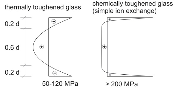
The investigated glasses were solely sodalime-silicat glasses, where an exchange of sodium and potassium ions leads to the desired stresses. To trigger the exchange, the glasses are immersed into a molten bath of potassic salt (e.g. saltpetre) at a temperature of 550 °C. Because of the different ionic radii of the ions, K+-ions (r = 0.144 nm) use 30% more room than Na+-ions (r = 0.096 nm), the surface of the glass is condensed and a compression zone is developed. The maximum value of the compression zone is proportional to the maximum ion exchange rate at the glass surface. For equilibrium reasons tensile stresses occur inside the glass.
The ion exchange can reach a depth of up to 300 µm. The achieved depth and prestress niveau in CTG are extremely dependent on the duration of the prestressing procedure. They rise with longer durations of the procedure, due to longer diffusion time. The imprinted prestress magnifies the mechanical strength of the glasses many times over, because defects on the surface, like micro or macro cracks and notches, which could cause breakage, are supressed. Crack propagation therefore, can only occur, when the effect of the impressed pre-tension has been overcome.
Hence, the compression zone depth respectively the ion penetration depth are crucial to the assessment of a critical crack depth. Generally, a treatment of 24 hours approximately equals a compression zone depth of 200 µm. Using thermal prestressing implementing a depth of 0.2*d is the norm, where d is the thickness of the prestressed glass sheet [8]. The consequence of this smaller compression zone depth is a greater sensitivity to surface damages, which result in a reduced flexural tensile strength, than observed in thermally strengthened glass.
In this article, the prestressing profile of chemically prestressed glass panes is investigated and two different measurement methods for recording surface compressive stress will be presented.
Photoelastic measurement methods
Due to the significantly lower compression zone depth of a chemically toughened glass, the measurement methods for determining the thermal prestressing cannot be transferred to such glass or can only be transferred to a limited extent. The information obtained with these methods is not sufficient for a valid stress determination in the compression zone of CTG. Therefore, it is necessary to use modified methods to characterize a chemical prestress profile which yield a higher information density regarding the compressive stress range of the glass. Scattered light measurement and refractometry are the chosen suitable optical methods.
1) Scattered light measurement (SCALP-05)
Scattered light measurement is a suitable method for non-destructive and local measurement of prestress profiles in transparent media [7]. Herein, the physical effect of light splitting in a glass pane not being affected by the stress component of the continuum lying in the lights direction is utilized.
This way, the state of tension in a continuum along an entering ray of light can be measured. While transmitting a transparent medium such rays are scattered or radiated at the glass particles lateral to the lights direction. The ray path becomes observable on the outside. This is called Tyndall effect. In a birefringent body the observation of the Tyndall effect can be used to draw conclusions about the state of stress prevailing in the body.
Using the Scattered Light Polariscope 05 (SCALP-05) the scattered light can be recorded precisely. The SCALP-05 therefore emits a polarised laser beam with a power of 5 mW and a wavelength of 635 nm. This beam enters the glass sample at an angle α via a prism (Fig. 2). An immersion fluid (refractive index n = 1.519) is applied between the prism and the sample. The former is used to avoid refraction of the laser beam.
![Figure 2: Measurement principle and measuring device SCALP-05 [7]](/sites/default/files/inline-images/Fig2_93.jpg)
The scattered light intensity is recorded along the laser beam and the optical path difference is determined up to the maximum measuring depth in the glass. The observed scattered light changes depending on the polarization direction, the local path difference and the observation direction. At an entry point of the laser beam with a flat contact surface, the path difference is zero; increasing with measuring depth, the path difference changes as a function of the locally prevailing stresses.
The SCALP-05 yields the advantage of a higher entry angle, compared to its predecessor. Latter ones laser beam enters the pane under an angle of α = 45°, while SCALP-05 uses an angle of α = 80°. This modification aids the special circumstance of an extremely thin compression zone in CTG. Induced by the flattening of the angle of incidence, the laser beam now travels a longer way in the relevant compression zone. This yields a four times higher information density in the compression zone.
On the other hand, the measurable depth in the pane shrinks to a maximum of 2.45 mm. Due to the low height of the compression zone, it is possible to characterize the tensile stress zone in the interior of the glass despite the low maximum measuring depth. Fig. 3 shows an example of the distribution of the optical retardation δ(η) over the thickness of a glass pane, its fitting curve and the calculated stress distribution for thermally and chemically tempered glass.
![Figure 3: Distribution of optical retardation and stress for a thermally toughened (left) and chemically toughened glass (right) [7]](/sites/default/files/inline-images/Fig3_84.jpg)
2) Stress measurement by light reflection at interfaces (refractometry)
Refractometry is an optical measurement method to determine refractive indices. It is based on the refraction of light at the interface between two optically differently dense materials [9], [10], [11]. When a light beam passes from an optically thinner medium (glass sample) to an optically denser medium (measuring prism), the angle of incidence and aperture of the beam differ. By comparing the refractive indices between the sample and a measuring prism (with known, high refractive index), the refractive properties of n optically thinner sample can be determined.
However, the used Abbé refractometer only permits the analysis of small material samples (approx. 2x2 cm). Therefore, only small sections of the glass panes could be examined.
The stress determination of CTG by light reflection at interfaces goes beyond the simple refractometric determination of refractive indices. CTG shows a gradient of the refractive index in the near-surface layers altered by ion exchange. Compressive stress and refractive index drop in the direction of the surface normal from the outside to the inside towards the refractive index of the base glass. CTG can thus be regarded as a layered medium. Each level of the compressive stress zone can be characterized as an intermediate layer with a different refractive index.
The chemically altered layers between the base glass and the prism, with a refractive index between that of the two media, thus alter the path of light through the body. Light entering this sequence of layers is now reflected or refracted by the optically different layers. Figure 4 shows the optical path of light over the boundary surfaces: prism – compression zone - base glass. Here nG is the refractive index of the base glass, nS(x) is the refractive index of the chemically modified surface layers and nP is the refractive index of the measuring prism.

Depending on the angle of incidence, the path length of the light differs in these chemically modified intermediate layers.
Adjacent rays emerging into the prism thus show an optical path difference δ. If the path difference corresponds to an integer multiple of the wavelength λ of the incident light, the light rays interfere positively when exiting into the prism. Interference lines appear in the ocular of the refractometer. Since toughened glass bodies exhibit the physical effect of birefringence, the use of non-polarized light results in a superposition of different interference patterns.
By irradiating polarized light (in the direction of the principal stresses), the interference patterns can be displayed separately. The now occurring interferences of the same order differ in their position and refractive indices, since the light rays travel different paths in the glass body according to their polarization direction (Fig. 5). The displacements of the interferences or the differences of the refractive indices that occur allow conclusions to be drawn about the surface tension of the glass.

Experimental analysis
Chemically toughened glass panes with different dimensions were studied for their stress profiles. All panes are chemically toughened glass panes manufactured using a simple ion exchange process. Stress profiles of panes with the dimensions b/h = 200/200 mm and thicknesses from 6 to 12 mm were studied. A pane with the dimensions b/h = 1100/360 mm and a glass thickness of 6 mm was used for the determination of the photoelastic constant of CTG.
1) Determining the photoelastic constant for CTG
In birefringent bodies, the photoelastic constant can be used to establish a relationship between the optical retardation of the light and the prevailing tension. It is used proportionally as a divisor in the stress calculation of SCALP and the refractometry and thus represents a decisive influencing factor for an exact stress determination. The photoelastic constant C varies between 2 and 5 TPa-1 depending on the chemical composition of the glass [12].
For thermally toughened float glass it is usually assumed to be 2.7 TPa-1 [7], [8]. There are no known values for CTG. For this reason, it was determined for CTG by means of experiments. The specimen used for this purpose, measuring 1,100 mm x 360 mm x 6 mm, was subjected to a four-point bending test (Fig. 6 and 7). In the metrologically relevant area - between the load applications - a constant moment was generated.
![Figure 6: Diagram of the test setup based on DIN EN 1288-3 [13]](/sites/default/files/inline-images/Fig6_66.jpg)
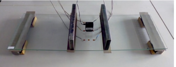
The photoelastic constant was determined through a series of measurements with SCALP (see Fig. 7) and the occuring strain during loading (measured via strain gauges). It results:

Since the optical retardation values δi of the incident light are determined by SCALP, α corresponds to the entry angle of the laser into the glass specimen, E is given as a material constant and ε is determined via the strain gauges, the photoelastic constant C can be determined with this test arrangement. After evaluation of several series of measurements, the photoelastic constant was determined to C = 3.03 TPa-1 and used for all further optical stress investigations on chemically toughened glass panes.
2) Photoelastic examination of the specimens
For the stress calculation, an anisotropic (direction-dependent) stress state in the glass has to be assumed. Therefore, measurements were performed in the direction of the two principal stress directions corresponding to the geometric axes of symmetry of the pane sample. Nine measuring points were determined for each pane. The measurements were carried out both on the tin bath side and on the air side. To reduce the error susceptibility of the measurement results, the result of the stress determination was averaged from at least four measurements. The measured values obtained by SCALP can be used to derive information on surface compressive stress, compressive stress zone depth and prevailing tensile stresses.
The measurements show that the measured surface compressive stresses as well as the tensile stresses in the glass core tend to increase as the pane thickness decreases. The applied compressive stress is proportional to the ion exchange carried out in the glass. The driving force for diffusion during production is the concentration gradient between glass and potassium melt as well as the process temperature.
Therefore the tendency is for thinner glasses to absorb heat more quickly under otherwise identical process conditions, thus increasing diffusion due to the lower mass. The tensile stresses create the stress or force equilibrium over the entire glass pane to compensate for the compressive stresses applied. Since the tensile stress zone is significantly larger than the compressive stress zone, low tensile stresses result in the pane core.
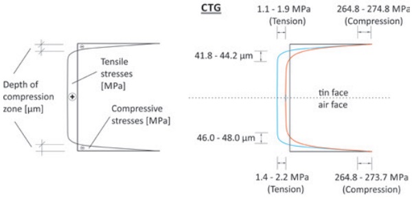
For the examined panes with thicknesses between 6 mm and 12 mm, the calculated values of the compressive stresses are between 274.8 MPa and 231.7 MPa; the tensile stresses are in a range between 2.2 MPa and almost 0 MPa. For the measured depths of the compressive stress zone, however, greater values were obtained with increasing pane thicknesses.
The values determined here are between 41.8 - 59.4 µm. Figure 8 shows the CTG tempering profile graphically across the glass cross-section. The stress profile (left) shows the general position of the compressive stresses, tensile stresses and compression zone depth at CTG. The profile shown on the right shows an example of the span of the measured data of a 6 mm thick glass pane in the corresponding graphic.
The surface pressure stresses determined by refractometry differ gradually from the measured values determined by SCALP. The stress difference is due to measurement inaccuracies of the refractometer used, since the refractive index can only be determined to three decimal places. This measurement accuracy is not sufficient for an exact determination of the stresses. Scattered light measurement using SCALP-05, on the other hand, provides more precise measurement results, is less time-consuming and nondestructive. Therefore, it is better suited for an exact classification of the prestressing profile and enables a practical application.
Summary and outlook
With the help of the newly developed measuring device SCALP-05 (scattered light measurement) developed by GlassStress Ltd. and refractometry, two methods are available for the basic characterization of a CTG stress profile. Of the methods of scattered light measurement and refractometry used, the first provides valid results for CTG with simple ion exchange. The compressive stresses, compressive stress zone depth and tensile stresses induced in the glass core can be determined.
Due to measurement inaccuracies, refractometric measurements should only be used as part of a comparative study with other measurement methods in order to avoid gross misinterpretation in the determination of stress. For quality assurance in the production of CTG, a combination of area-wide determination of the position of the preload minima (e.g. via diffusion profiles) and punctual checking of these with SCALP-05 is recommended.
The presented measurement methodology will be used for glasses with simple ion exchange as well as for novel CTG products. Due to the low pressure zone depth currently achieved with CTG, the manufactured glasses are susceptible to a reduction in strength due to surface damage. Therefore, a new manufacturing process is planned which produces chemically-thermally combined prestressing profiles in order to shift the compressive stress zone and its maximum into deeper glass layers. The aim of this process is to significantly increase the resistance of CTG to surface damage.
References
[1] EN 12150: Glas im Bauwesen - Thermisch vorgespanntes Kalknatron-EinscheibenSicherheitsglas, 2015
[2] EN 1863: Glas im Bauwesen - Teilvorgespanntes Kalknatronglas, 2012
[3] Feldmann, M. et. al.: Flächige und zerstörungsfreie Qualitätskontrolle mittels spannungsoptischer Methoden, Glasbau 2017, Ernst und Sohn Verlag Berlin, 2017
[4] Nordberg, M.; Mochel, E.; Garfinkel, H.; Olcott, J.: Strengthening by Ion Exchange Journal of the American Ceramic Society, V. 47, 1964
[5] Heinze, R.; Schaeffer, H.: Spannungsaufbau beim Ionenaustausch von Gläsern Glastechnische Berichte, Nr.47, 1974
[6] Arbeitsgemeinschaft industrieller Forschungsvereinigung, AIF/ZIM Forschungsantrag: „Entwicklung eines sicher reproduzierbaren industriellen Verfahrens zur Glashärtung mit definierten und messbaren Vorspannungsprofilen zur Anwen-dung in verschiedenen Bereichen“ Unveröffentlicht, 2013
[7] Glass Stress Limited: Handbuch für „Scatterd Light Polariscope“ (SCALP-05), Vers. 5.3, 2013
[8] Feldmann, M.; Kasper, R.; Langosch, K.: Glas für tragende Bauteile Werner Verlag, 2012
[9] Acloque, P.; Guillemet, C.: Spannungsmessung durch ein Spiegelungsverfahren Silikattechnik 11, 1960
[10] Ruppert, F.: Messung und Berechnung von Spannungen in chemisch vorge-spannten Gläsern Studienarbeit, Universität Erlangen-Nürnberg, Lehrstuhl für Glas und Keramik, 1990
[11] Schiffner U.: Ein oberflächenempfindliches, zerstörungsfreies Spannungsmeß-verfahren chemisch vorgespannter Gläser und der Einfluß von Kationen in Kali-umnitratschmelzen auf den Spannungsaufbau, Diplomarbeit, Universität Erlangen-Nürnberg, Lehrstuhl für Glas und Keramik, 1981
[12] Aben, H.; Guillement, C.: Photoelasticity of Glass, Springer Verlag, Berlin 1993
[13] DIN EN 1288-3: Glas im Bauwesen – Bestimmung der Biegefestigkeit von Glas – Teil 3: Prüfung von Proben bei zweiseitiger Auflagerung (Vierschneiden-Verfahren) Beuth Verlag, 2007
[14] DIN EN 12337-1: Glas im Bauwesen – Chemisch vorgespanntes Kalknatronglas – Teil 1: Definition und Beschreibung, Beuth Verlag, 2000


