Article Information
- Digital Object Identifier (DOI): 10.47982/cgc.9. 538
- Published by Challenging Glass, on behalf of the author(s), at Stichting OpenAccess.
- Published as part of the peer-reviewed Challenging Glass Conference Proceedings, Volume 9, June 2024, 10.47982/cgc.9
- Editors: Christian Louter, Freek Bos & Jan Belis
- This work is licensed under a Creative Commons Attribution 4.0 International (CC BY 4.0) license.
- Copyright © 2024 with the author(s)
Authors:
- Tom Reisewitz - University of the Bundeswehr Munich
- Alexander Pauli - University of the Bundeswehr Munich
- Geralt Siebert - University of the Bundeswehr Munich

Abstract
Structural glazing joints in glass construction are subject to dynamic earthquake loads in certain regions. To date, however, there is no recognized proposal for the design of such situations. The verification for earthquake loads is either neglected for glass structures or carried out with equivalent values for the entire building. Not considering the behaviour of the bonded joints under dynamic loading might be insufficient, especially in the presence of heavy glass elements. Dynamic loads on bonded glass constructions with silicones or polyurethanes influence the structural design concerning resistance and influence. The load-bearing capacity of the structural sealant might be reduced on the one-hand side, while the impact on the bond might be decreased on the other-hand side. A more thorough investigation of the structural performance of silicone within bonded glass structures under different loading scenarios is urgently required and an appropriate material model is essential. The calibration of this model is crucial to better understand the performance under dynamic loading. A hyperviscoelastic material model, which considers time-dependent properties and large deformations, seems promising. The aim is to identify the material parameters for this model based on dynamic mechanical thermal analysis and tensile tests.
1. Motivation
Structural sealant glazing (SSG) is increasingly being used for aesthetic and transparency reasons. Structural glazing joints in glass and facade construction are subject to external influences such as wind, temperature changes and dead weight. In certain regions, it is also necessary to consider exceptional load situations, such as dynamic earthquake loads. However, there is currently no accepted design proposal for such scenarios.
The seismic design of glass and facade structures has been either neglected or performed using equivalent values for the entire building. This approach is particularly inadequate for heavy facade or glass elements, as it does not adequately account for the structural behaviour of the bonded joints under dynamic loading. As a result, uncertainties must be accepted in current design without defined standards.
Therefore, a more thorough investigation of the load-bearing behaviour of bonded glass and facade structures is urgently needed, considering appropriate load scenarios. The use of an appropriate material model is essential for this purpose.
The calibration of such a material model is crucial to better understand and evaluate the performance of glass and facade structures under dynamic loading. The use of a hyper viscoelastic material model implemented in the Finite Element Method (FEM) software ANSYS, seems promising. Therefore, this work aims to identify the appropriate material parameters for such a model based on Dynamic Mechanical Thermal Analysis (DMTA) and uniaxial tensile tests.
The FKG Leaflet "Tragende Silikonklebstoffe im Konstruktiven Glasbau" (2021) of the Bonding Working Group describes the current state of the art for structural silicone adhesives, beyond the current technical regulations for structural glass applications ETAG 002 (2012). It should be noted that numerical calculations with the finite element method using equivalent springs or 3D solid elements are proposed for the design of silicone bonds. However, only a linear elastic material model is proposed to represent the bond, which does not consider time dependencies and cannot adequately represent large deformations. This approach is inadequate when considering dynamic loads and very large deformations, such as those that occur during earthquakes.
In addition to the FKG Leaflet (2021) and the ETAG 002 (2012), many studies have already been carried out on silicones and the characterization of material behaviour. Kießlich et al. (2022) compared various hyperelastic material models for the simulation of H specimens. The model according to Yeoh (1990) and Ogden (1972) proved to be the most suitable. However, as with Drass (2020), who developed a new hyperelastic model, no time dependence of the material was considered. Schaaf (2024) took the time dependency into account in a calculation method that extended Hook's elasticity by a strain rate dependency. However, only small deformations are considered here.
By taking into account the time dependence and large deformations, it should be possible to more accurately simulate the behaviour of bonded glass and facade structures under different load scenarios. This allows for more accurate prediction of stresses and deformations during operation under real conditions.
2. Methods
2.1. Linear viscoelasticity and hyperelasticity
The Generalized Maxwell Model is one of the most important material models for linear viscoelasticity. It consists of several Maxwell elements connected in parallel and supplemented by a parallel spring. The more Maxwell elements are used, the more accurate, the model becomes. For the mathematical description of this model, a so-called Prony series can be used to describe a time-dependent modulus. The Prony series consists of k stiffness relaxation functions with associated relaxation times 𝜏k and an infinity stiffness 𝐸∞. Alternatively, the Prony series can be formulated with the standardized modulus 𝑔k= 𝐸K/𝐸0, where 𝐸0 is the modulus of elasticity at time t = 0:

Hyperelasticity is used to describe the behaviour of rubber-like materials under large strains. These materials consist of long molecular chains. As the orientation of these chains is random, isotropic behaviour can be assumed for these materials. Furthermore, full or nearly incompressibility can be assumed. From a mechanical point of view, the material behaviour is shown to be purely elastic, but non-linear. This means that the deformation is completely recovered when the load is removed. Time dependence does not effect on the material response. Several forms of strain energy potentials describe the hyperelasticity of materials. These are based on either strain invariants or principal stretches. Here the approach of Yeoh (1990) based on a formulation in terms of invariants was chosen, whose strain energy potential results are as follows:
![]()
Where 𝐼⁻1 is the first invariant of the deviatoric part of the right Cauchy-Green deformation tensor, J is the determinant of the deformation gradient F, and 𝑐𝑖₀,𝑑𝑘 are the material constants. The initial shear modulus is defined by:
![]()
And the initial bulk modulus is defined as:
![]()
For N=1, the Yeoh formulation is equal to the Neo-Hookean formulation. Yeoh's approach was chosen because it is able to visualize different deformation states equally well based on the parameters from a tensile test.
Since the silicone adhesive DOWSIL 993 is subject to both large deformations and time-dependent behaviour, a combination of viscous and hyperelastic material behaviour is required. This approach is called Hyperviscoelasticity or Large-Strain Visco-Hyperelasticity and has been derived by Simo (1987)and was further developed by Holzapfel and Simo (1996) and Holzapfel (1996). According to Simo and Holzapfel, the viscoelastic constitutive equation for large strains, in terms of the second Piola-Kirchhoff stress, is given by:
![]()
These approach differs from the generalized Maxwell element (cf. Eq 1) in that the stress is divided into volumetric and deviatoric components and the initial stiffness 𝐸𝐸0 is replaced by the hyperelastic Yeoh potential.
2.2. Time-temperature-superposition principle
Polymers generally exhibit a pronounced time and temperature dependence of their properties due to molecular motion and rearrangement processes. These processes, which determine the relaxation and retardation spectra, accelerate with increasing temperature. As a result, the relaxation and retardation time spectra shift to shorter times at higher temperatures. If only the rate is changed, but not the type and number of molecular processes, the shape of these spectra along the logarithmic time axis remains the same, which is referred to as "thermorheologically simple". However, the position of these spectra changes with temperature. The time-temperature-superposition principle uses this time-temperature equivalence to predict long-term behaviour (Schwarzl 1990; Grellmann 2015). By horizontally shifting curves at different temperatures to coincide with a selected reference curve, a master curve is created that represents the material's behaviour over a wide range of time.
2.3. Method “GUSTL”
A suitable method is needed to shift the curves so that the master curve is as smooth as possible. The "GUSTL" method by Kraus and Niederwald (2017) provides both an approach for shifting the individual characteristic curves and an algorithm for identifying the Prony parameters to describe the corresponding master curves. The advantage of this method compared to other established methods (Tschoegl 1989; Kuntsche 2015) is the speed of parameter identification without losing accuracy.
3. Experiment
3.1. Material and specimen production
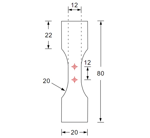
The tests were carried out using Dow's DOWSIL 993 silicone, which is approved for glass facade construction. Dogbone specimen with a thickness of approximately 3 mm were produced in November 2021. Therefore, the silicone was sprayed onto a polyethylene plate between two 3 mm thick steel sheets and then stripped to create a flat surface from which the test specimens could be die-cut. The remaining dimensions of the dogbone specimens are shown in Figure 1. The modified geometry, taken from Becker (2009), compared to the dimensions in DIN EN ISO 527-2 (2012) enables better digital image correlation during the tensile tests. In addition, larger strains and higher strain rates can be realized. The specimens were stored until conducting the tests at a room temperature of about 20°C and a humidity of about 50%. The dogbone specimens could be used directly for the tensile tests, while the specimens for the DMTA tests were die-cut out of the dogbone specimens already produced in 2021. Rectangular specimens (10 mm x 40 mm) were used for the DMTA tests.
3.2. DMTA-Experiments
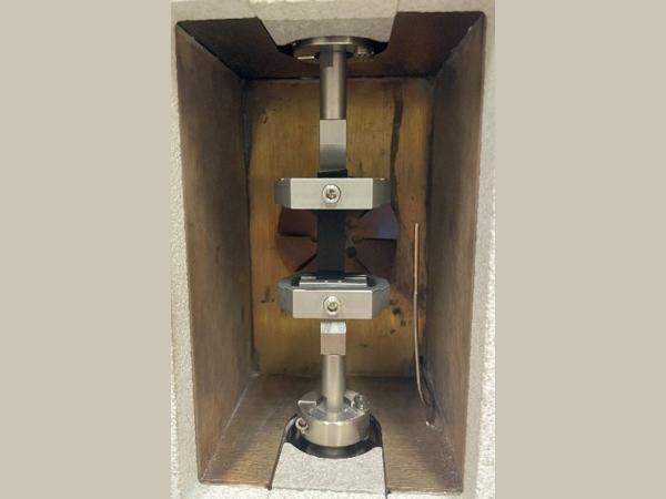
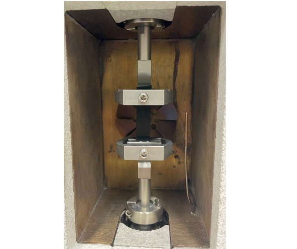
DMTA is a suitable method to determine the characteristic curves of time-dependent stiffness at different temperatures. The DMTA tests were performed in a Gabo EPLEXOR 2000N materials testing machine from Netzsch. DMTA can be used to test a polymer's viscoelastic properties, stiffness, and damping behaviour as a function of temperature and frequency. A temperature-frequency sweep was selected as the measurement mode. The loss factor tan(δ), storage modulus E', and loss modulus E'' were determined for each specimen and each temperature step for each frequency tested. The tested temperatures ranged from 80°C to -20°C and 11 frequencies from 0.5 Hz to 50 Hz were tested in 5°K steps. The Prony parameters were then determined using the time-temperature shift principle and the GUSTL method (Kraus 2019). The thickness of each specimen was measured bevor testing to calculate the cross section. The length and width of the die-cut specimens were 10 mm x 40 mm, the length between the clamps was 20 mm (Fig. 2).
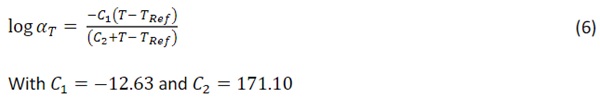
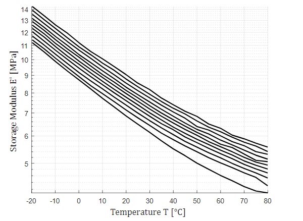
The averaged DMTA results, plotted as storage modulus versus temperature, for the five specimens are shown for all 11 frequencies in Figure 3. The DMTA results are read in with a MATLAB script and the GUSTL method is applied. A reference temperature of 20°C is chosen. The shift function follows the WLF approach (Williams et al. 1955) with the following values:
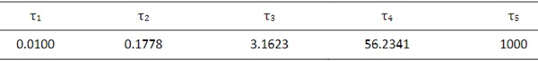
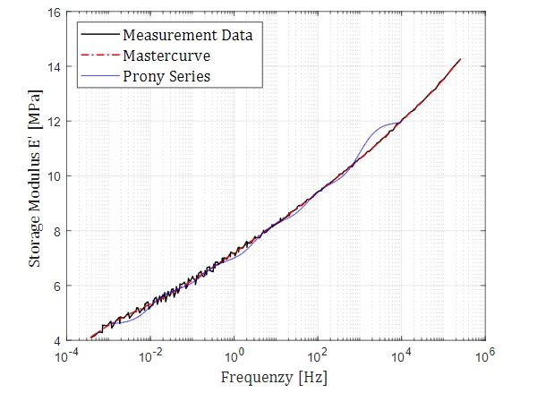
The curves of the measured data, Mastercurve and Prony series for the storage modulus in the frequency domain are shown in Figure 4. For each Maxwell element within the Generalized Maxwell Model, a relaxation time 𝜏k and a stiffness component concerning to the total stiffness 𝑔k are obtained according to Formula 1. The following results are obtained for the tests performed:
Table 1: Stiffness components in relation to the total stiffness 𝑔k.
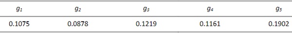
Table 2: Relaxation times 𝜏k.
3.3. Tensile tests
The tensile tests were performed in a 20°C conditioned test container using a ZwickRoell zwickiLine Z2.5. Following ETAG 002 (2012), a strain-controlled test sequence with a strain rate of 5 mm/min was selected. To account for the Mullins effect and the resulting damage and softening of the stress-strain curve (Mullins 1969), three load cycles were applied at 50 mm/min to a max. displacement of 62 mm and then relieved to 3 N. The final cycle was relieved to 1.9 N. When the force dropped below 2 N, the ARAMIS Adjustable 3D optical measuring device automatically started the measurement, triggered by the force signal from the load cell. The tensile test followed at a strain rate of 5 mm/min up to a displacement of 57 mm. The 57 mm was chosen so that more than 150% engineering strain could be imaged. The 62 mm was chosen for the damage cycles because the damage cycle must extend beyond the measurement range.
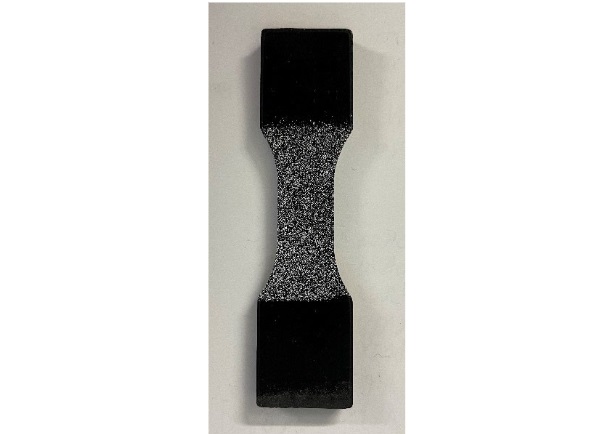
To record the strain in the center of the specimens during the tensile tests, the black silicone specimens were provided with a white speckle pattern from a spray can, which could be recorded and evaluated by the ARAMIS Adjustable 3D system utilizing digital image correlation, see Figure 5. In the ARAMIS Adjustable 3D software, a measurement window was defined in the central, constant area of the specimens, for which the true strain in the longitudinal and transverse directions was output for each recorded image. A measuring frequency of 0.5 Hz was selected. From the strain and the corresponding force signal, the true stress could be calculated for each image. A transverse contraction of approximately ν=0.485 was determined from the strain in the load direction and orthogonal to it, indicating almost complete incompressibility. For the mean values of the five specimens, the true stresses over the true strains within the measurement cycle are shown later (Fig. 7). The measured values for the measurement cycle do not pass through the origin because the specimens were not completely relieved after the damage cycles. This was done to achieve the most consistent conditions possible for each test.
4. FE modelling ANSYS
4.1. Material parameter identification using MATLAB
For parameter identification, the hyperviscoelastic material model (see 2.2) was reduced to the uniaxial stress state and implemented in MATLAB assuming incompressible material behaviour. The response of the model is calculated according to the test specifications. On the other hand, the stress-strain relationship in the tensile direction was evaluated from the optical measurement. The difference between the calculated and measured stress was implemented as an error function in the global optimization algorithm "global search", which is based on the local solver "fmincon". Only the stress of the last reload cycle was used as the measured stress. This means that the parameter identification is carried out for the material that has already been damaged. At this point, the influence of the Mullins effect has already set in.
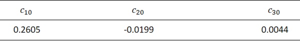
For the subsequent optimization process, the already identified Prony parameters were retained and only the parameters of the Yeoh model were varied. The parameter set with the lowest error is shown in Table 3.
Table 3: Material parameters 𝑐𝑖₀.
4.2. Implementation ANSYS
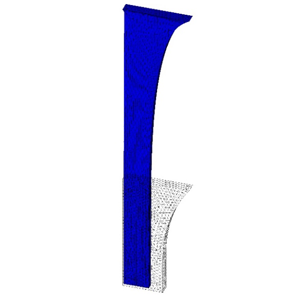
Due to symmetry conditions, only 1/8 of the shoulder sample was simulated considering respective boundary conditions (Fig. 6). Consequently, only half the deformation of 28.5 mm was applied. The time for applying the deformation was adjusted to maintain the test velocity of 5 mm/min. Solid186 elements with a mixed u-P formulation were used for the simulation as these elements support the representation of nearly incompressible hyperelastic material behaviour. The element edge length was set to 0.5 mm. Since the compressive modulus was not considered in the MATLAB optimization due to the assumption of incompressibility, a corresponding value was chosen in the FEM model.
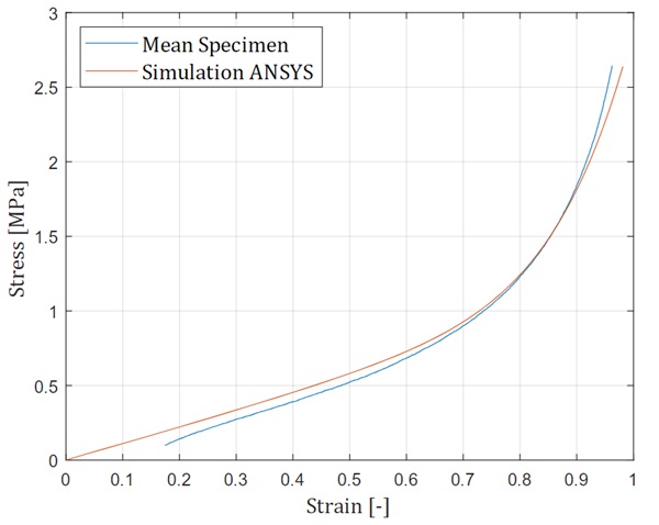
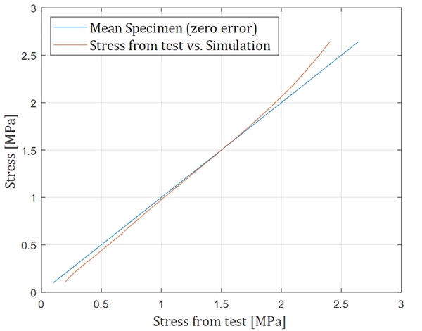
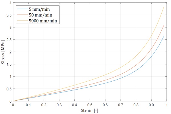
Figure 6 shows the deformed and undeformed geometry of the 1/8 specimen. The tremendous deformation of the specimen is clearly seen, and all physical boundary conditions for the specimen section have been satisfied. As a result, the true stresses and true strains in the loading direction at a node in the global centre of the specimen, related to the entire geometry, were output. The stress-strain diagram is shown in Figure 7 along with the mean test values. The stress-strain curves represent the material behaviour after three previous damage cycles related to the Mullins effect. This means that the stress-strain behaviour does not represent the stress-strain behaviour of new material. In the initial range, the simulation results show a slightly higher stiffness than the average test results. Between a strain of 0.7 and 0.9, the two results are very close. From a strain of 0.9, the test results show a greater increase in stiffness. Overall, however, the simulation and experimental results are close to each other. A better look at the error is given in Figure 8, which shows the error between test and simulation. Figure 9 shows simulated stress-strain curves at different strain rates, from 5 mm/min to 5000 mm/min. Due to the low loss modulus of the material, the curves are close together, because the time dependence has little effect on the slope. However, these results need to be confirmed with further experiments.
5. Discussion
A major advantage of the calibrated model is its ability to accommodate large deformations and time- and temperature-dependent behaviour. This allows a more accurate representation of the real behaviour of bonded glass and facade constructions under different loading scenarios.
However, it does not account for the so-called Mullins effect, which may limit its applicability in certain situations. However, the behaviour of the model is calibrated according to damage cycles, making it a practical 'engineering approach'. However, the model can be extended within ANSYS to include the Mullins effect.
Another disadvantage of the model is its limitation to tensile tests with a specific stress state and strain rate. To test the models validity in different contexts, further research is needed.
6. Outlook
In conclusion, the material model calibrated from the DMTA tests and the optimization process is suitable to represent both the hyperelastic and the viscous material behaviour simultaneously, even for large strains. Further investigations are needed to obtain a reliable material model:
- Simulation of other strain rates / stress states
- Simulation of cyclic loading / earthquake loads
- Simulation of different temperatures
And the validation with corresponding tests. To create and calibrate a design model for structural sealant glazing under seismic loading, a failure criterion is also required. Studies on this have already been done by e.g. Rosendahl (2020) and Drass (2020).
References
Becker, F.: Entwicklung einer Beschreibungsmethodik für das mechanische Verhalten unverstärkter Thermoplaste bei hohen Deformationsgeschwindigkeiten. Martin-Luther University Halle-Wittenberg Phd. Thesis (2009)
DIN EN ISO 527-2: Kunststoffe - Bestimmung der Zugeigenschaften - Teil 2: Prüfbedingungen für Form- und Extrusionsmassen (ISO 527-2:2012); Deutsche Fassung EN ISO 527-2:2012. (2012)
Drass, M.: Constitutive Modelling and Failure Prediction for Silicone Adhesives in Façade Design. Springer Vieweg Wiesbaden (2020)
ETAG 002/1: Guideline for European Technical Approval for Structural Sealant Glazing Kits (SSGK) Part 1: Supported and Unsupported Systems, (2012)
Fachverband Konstruktiver Glasbau e.V.: Merkblatt FKG 01/2021 Tragende Silikonklebstoffe im Konstruktiven Glasbau (2021)
Grellmann, W., Seidler, S.: Kunststoffprüfung, Carl Hanser Verlag, München (2015)
Holzapfel, G.A., Simo, J.C.: A new viscoelastic constitutive model for continuous media at finite thermomechanical changes. International Journal of Solids and Structures, Vol. 33, No. 20- 22, pp. 3019-3034, 1996
Holzapfel, G.A.: On large strain viscoelasticity: Continuum formulation and finite element applications to elastomeric structures. International Journal for Numerical Methods in Engineering, Vol. 39, 3903-3926 (1996)
Kießlich, P., Giese-Hinz, J., Wünsch, J., Louter, C., Weller, B.: Praxisorientierte Fehleranalyse nichtlinearer Modelle für strukturelle Silikone. Ernst&Sohn ce/papers 5, 1, (2022), 294-307
Kraus, M.A., Niederwald, M.: Generalized collocation method using Stiffness matrices in the context of the Theory of Linear viscoelasticity (GUSTL). Technische Mechanik 37, 1, (2017), 82 – 106
Kuntsche, J. K.: Mechanisches Verhalten von Verbundglas unter zeitabhängiger Belastung und Explosionsbeanspruchung. Springer Vieweg, Berlin (2015)
Mullins, L.: Softening of Rubber by Deformation. Rubber Chemistry and Technology (1969) 42 (1): 339-362
Ogden, R.W.: Large deformation isotropic elasticity – on the correlation of theory and experiment for incompressible rubberlike solids. Proc. R. Soc. Lond. A 326 (1972), 565–584
Rosendahl, P.L.: From Bulk to Structural Failure: Fracture of Hyperelastic Materials. Mechanik, Werkstoffe und Konstruktion im Bauwesen. Band 57. Springer (2020). https://doi.org/10.1007/978-3- 658-31605-1
Schaaf, B.: Zum Tragverhalten hyperelastischer Klebverbindungen im konstruktiven Glasbau. Verlag Mainz (2024)
Schwarzl, F.R.: Polymermechanik. Struktur und mechanisches Verhalten von Polymeren. Springer, Berlin (1990)
Simo, J.C.: On a fully three-dimensional finite-strain viscoelastic damage model: Formulation and computational aspects. Computer Methods in Applied Mechanics and Engineering, 60 (1987) 153-173
Tschoegl, N. W.: The Phenomenological Theory of Linear Viscoelastic Behavior. Springer, Berlin (1989)
Williams, M.L., Landel, R.F., Ferry, J.D.: The Temperature Dependence of Relaxation Mechanisms in Amorphous Polymers and Other Glass-forming Liquids. J. AM. Chem. Soc. (1955), 77, 14, 3701-3707
Yeoh, O.H.: Characterization of elastic properties of carbon-black-filled rubber vulcanizates. Rubber Chemistry and Technology (1990) 63 (5): 792-805


 demonstrator at Glass Technology Live during Glasstec 2024 (© Cas Maertens).")