This paper was first presented at GPD 2023.
Link to the full GPD 2023 conference book: https://www.gpd.fi/GPD2023_proceedings_book/

Authors: Adam Nizich, PE Eckersley O'Callaghan, New York, USA
Adam Nizich is a Senior Engineer with Eckersley O’Callaghan’s New York office. Adam applies a first principles approach to the design, engineering, and consulting on innovative facade and structural glass applications. He has collaborated on research for the development and application of effective thickness methods for laminated glass structural design and is currently leading the development of a new ASTM effective thickness standard.
Abstract
Laminated glass fins are a remarkably slender application of structural glass and are sensitive to lateral-torsional buckling from in-plane flexural forces. Development of flexural and torsional stiffness is critical to their flexural stability, and therefore, the accurate assessment of the partially composite stiffness is key to evaluation of their structural performance.
Effective thickness is an analytical method for the determination of equivalent monolithic section properties and is useful for evaluation of laminated glass structural performance using classic analysis methods. Multiple effective thickness values representing membrane, flexural, and torsional stiffness can be applied in hand calculations for basic design cases; however, representation of two or more effective thickness values in a finite element analysis (FEA) model presents a particular challenge for simplified numerical analysis. Furthermore, limited information is available on the evaluation of effective torsional properties of multilaminate sections with n-number of plies, commonly used in glass fins, presenting an additional limitation for simplified analysis of contemporary applications.
In this paper, Sandwich Theory effective thickness is applied to the evaluation of multilaminate glass fin stability for in-plane flexure. To address the challenge of processing membrane-, flexural-, and torsional-effective thicknesses in a simplified FEA model, an effective stiffness matrix for thin shell elements is proposed and benchmarked with detailed layered FEA models.
Introduction
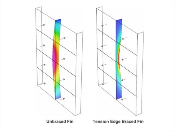
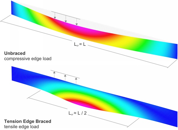
Glass fins are transparent structural elements composed of two or more laminated glass plies primarily designed to support in-plane bending forces. Their stability against lateral-torsional buckling (illustrated in Figure 1) is is sensitive to bending and torsional stiffness developed by the shear coupling of the plies across the interlayer. Assessment of the partially composite stiffness is therefore critical for their design.
Adopted from the study of composite sandwich panels, effective thickness (ET) is a method for the simplified evaluation of laminated glass (LG) with an equivalent monolithic thickness corresponding to the interlayer shear modulus Gint, bounded by the non-composite layered and composite monolithic limits of the glass plies. ET methods have advanced considerably since publication of the Bennison-Wölfel method [1], as included in ASTM E1300 [2] for out-of-plane bending of simply-supported beams, to address numerous loading and boundary conditions. Notably, Luible’s adoption of Stamm and Witte’s torsional stiffness for sandwich structures [3, 4] is recognized as a key development for the simplified evaluation of glass fins.
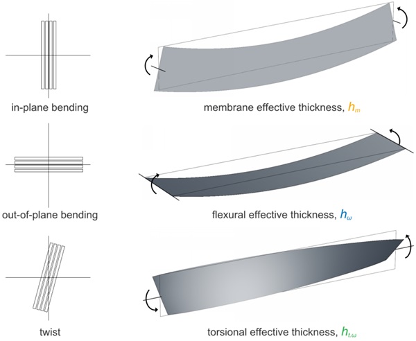
Evaluation of glass fin stability requires a minimum of three ET values; one representing each axis of bending and twist of a LG fin, as illustrated in Figure 2. The combined use of flexural and torsional-ET values allows for the analytical analysis of basic LG fin applications with beam theory hand calculations for basic design cases.
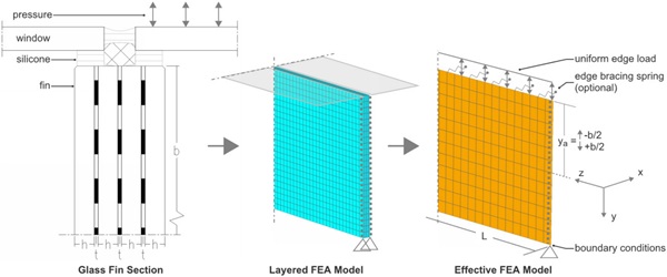
Combined axial and flexural loads, uneven load distributions, and relative bracing by a series of structural silicone glazed windows are examples of real-world conditions that together can be cumbersome to evaluate with hand calculations. These real-world conditions can be rationally assessed with a numerical finite element analysis (FEA) model of the complete system (Figure 3). The key to a good FEA model is developing an approach that is as simple as possible to obtain the desired results. That can be accomplished for stability evaluation of glass fins by using ET values to define representative shell element stiffness to avoid modeling each LG layer, as depicted in Figure 4. However, representation of two or more effective thickness values in a shell elements based on one isotropic thickness presents a particular challenge for simplified FEA analysis.
To address this challenge, an effective stiffness matrix for thin shell elements is defined to simplify the numerical evaluation of LG fins and more broadly – structural glass systems.
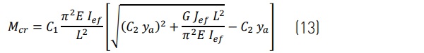
![Figure 3 – Comparison of lateral-torsional critical buckling shapes for unbraced and edge braced glass fins. [Strand7].](/sites/default/files/inline-images/Fig3_341.jpg)
Effective Thickness
Multilaminate sections are standard in many structural glass applications with significant spans and post-fracture loading requirements. Therefore, simplifying analysis of multilaminate glass lites is of interest. Below, effective thickness formulas for sections with n-number of plies with equal thickness, h, are presented for evaluation of membrane-, flexural-, and torsional-ET. The expressions presented here extend the Bennison-Wölfel flexural-ET method proposed by Calderone et. al [1] for 2-ply beams and the torsional-ET method proposed by Luible [3] and further applied by Bedon and Amadio [5] for 2-, and 3-ply beams. Collectively, this method is referred to here as Sandwich Theory (ST) effective thickness.¹
¹ The Enhanced Effective Thickness (EET) method for multilaminates [6] also has excellent correlation for LG in bending for a wider set of loading and boundary conditions, however, its torsional-ET is not as precise for glass fin applications [7, 8].
The glass plies, without interlayers, are responsible for the membrane stiffness of a LG section. Therefore, the definition of membrane-ET, hm, in Eq. 1 is simply the sum of minimum glass ply thickness h. It is applied to define strong axis (x-x) bending and axial (z-z) section properties:
![]()
The corresponding strong-axis effective moment of inertia useful for evaluation of first-order deflection and stress is:
![]()
As defined in ASTM E1300 [2] for 2-ply LG beams, flexural-ET is a function of the shear coupling, Γ, of glass plies and interlayers in bending over development length, a, for an interlayer shear modulus, Gint . When flexural buckling is considered, the composite development length, a, must agree with the critical buckling length between inflection points, Lcr , such that a ≤ Lcr [5]. Shear coupling is expressed in Eq. 3 for evaluation of a multilaminate section with a sinusoidal bending moment:
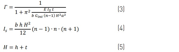
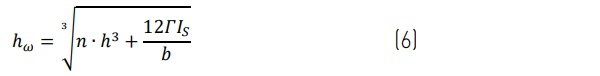
Flexural-ET, hω, is then determined for the LG lite with Eq. 6:
The corresponding weak-axis effective moment of inertia is:
![]()
Torsional stiffness is a function of the shear development in twisting across section depth, b [3, 5]. This is convenient since torsional effective stiffness is not a function of the buckling length. The torsional-effective polar moment of inertia, Jef , is evaluated as:

where:
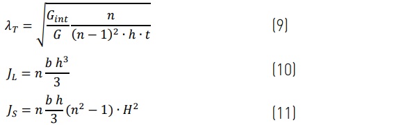
Torsional-ET, ht.ω, of a thin beam is then simply:
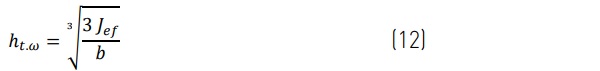
The effective thickness values are compared in Figure 5 for the example 4-ply fin in Figure 4 with a span of a = 8,000 mm and a depth of b = 600 mm, with a h = 7.7 mm minimum glass ply thickness, an elastic modulus of E = 70,000 MPa, a Poisson’s ratio ν = 0.23, a corresponding shear modulus of G = 28,455 MPa, and a t = 1.52 mm interlayer ply thickness. Observe in Figure 5 that torsional-ET is offset below flexural-ET for the full range of interlayer shear moduli Gint = 0.1 … 1,000 MPa corresponding to a decreased stiffness; a lower torsional-ET is characteristic of LG fins.
![Figure 6: Thin Shell Effective Stiffness Matrix [K] for Glass Fin Evaluation](/sites/default/files/inline-images/Fig6_289.jpg)

Effective Stiffness Matrix
The effective thickness values representing stiffness may thoughtfully be applied to define a thin shell stiffness matrix for finite element analysis. The stiffness matrix [K] for a thin shell element is the combination of a membrane stiffness matrix [Dm] for in-plane axial and shear forces, and a bending stiffness matrix [Db] for out-of-plane bending and torsion. An isotropic shell element (such as one representing a monolithic lite of glass) is typically based uniform thickness for both membrane and torsional stiffness.
Given that membrane-ET is non-composite, the membrane-ET term hm is uniformly assigned to the membrane stiffness matrix [Dm]. The flexural-ET term hω and torsional-ET term ht.ω are assigned to the bending stiffness matrix [Db], as formally expressed in the thin shell effective stiffness matrix in Figure 6.
Stiffness scale factors may alternatively be defined to adjust the stiffness of an isotropic shell element and eliminate the burdensome definition of a stiffness matrix. For example, in Strand7 Finite Element Software [9] the membrane and bending stiffness can be independently assigned based off the respective ET values, allowing the torsional stiffness term to simply be factored as an attribute by (ht.ω /hω )³. Similarly, density or mass may be factored to correct the lite unit weight.
Linear Buckling Analysis
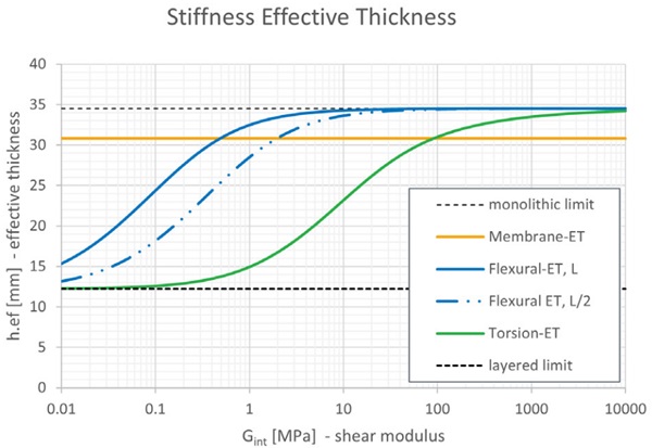
Lateral-torsional critical buckling, Mcr, predicted with analytical and numerical analyses methods based on effective thickness values are compared with results from a layered numerical model. The following Euler buckling formulas² for an unbraced span referenced by Luible [3], and with tension edge bracing referenced by Bedon [11], are applied for analytical analysis:
with coefficients C₁ = 1.13 and C₂ = 0.46 applied for a parabolic bending moment from a uniform in-plane load and where ya is the distance from the centroid to the applied load, positive for a compressive edge loading.
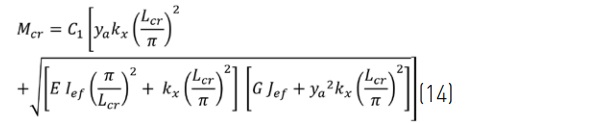
where ya is the distance from the centroid to the edge bracing and is negative for a tension edge loading. Since edge bracing will reduce the critical buckling length, Lcr , it is necessary to consider a critical buckling length corresponding to the shortest half-sine length between inflection points of the buckled shape, such that Lcr ≤ L / nR (Figure 7) , where, nR , is the number of half-sine wave lengths. For our example, an edge bracing stiffness kx = 1 MPa is adopted to represent the shear stiffness of two 6 mm wide by 6 mm thick structural silicone bites.
² The Australian glass standard AS 1288 [10] lists additional critical buckling formulas for a variety of fin bracing conditions and can also be considered in analytical analysis provided meaningful consideration is made to the buckling length, flexural and torsional stiffnesses based on restraints and laminated glass effective section properties.
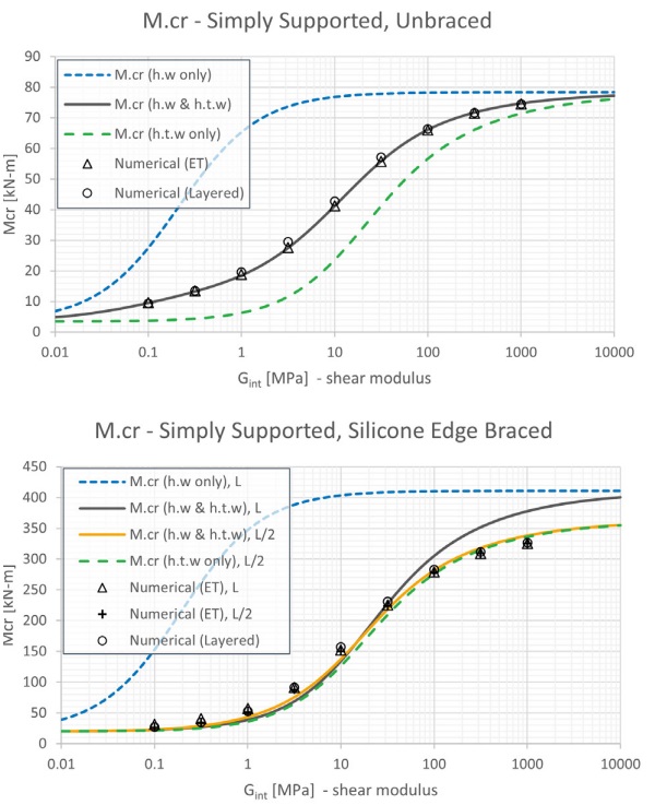
The critical buckling performance of the fins in Figure 8 are bounded by the flexural and torsional stiffness limits indicated with dashed lines, where the corresponding effective thickness is assumed for both flexural and torsional stiffness. Good correlation between the predicted lateral-torsional buckling performance of the unbraced fin is observed in Figure 8.a for all analysis models.
The stability of the fin is strongly influenced by the torsional stiffness for both the unbraced and tension edge braced conditions and is generally observed to track well below the upper bound flexural stiffness limit. In the case of the tension edge braced condition in Figure 8.b, the performance nearly aligns with the lower-bound torsional stiffness limit for a critical buckling length corresponding to nR = 2. This demonstrates that edge bracing’s influence on the half-sine buckling length is an important consideration (Figure 7), however, refinement of the flexural-ET in this example is not critical since the performance is dominated by the torsional stiffness. Where further calibration of the flexural-ET is necessary, the interactive approach proposed Lenk and Lancaster [12] may be considered with a constant torsional-ET.
In the design practice, evaluation of torsionalET is often overlooked with stiff interlayers which correspond to a high flexural-ET in LG fins. As verified in this example, neglecting the torsional-ET by assuming of flexural-ET s considerably unconservative in both the unbraced and edge braced analyses.
Second-Order Analysis Considerations
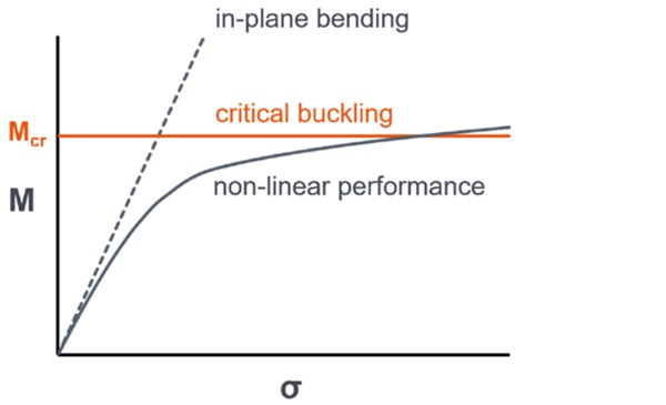
Critical buckling is an upper bound estimation of load carrying capacity and does not take into account stress amplification effects [Figure 1] that may fail glass in tension from out-of-plane bending at a fraction of the critical buckling value. As proposed in the draft Eurocode CEN/ TS 19100 for the design of glass structures [13], where the applied load is greater than 10% of the critical bucking capacity, secondorder stress amplification effects are to be considered in a rational analysis. Based on examination of lateral-torsional buckling behavior, a layered model is often necessary for evaluation of stresses due to second-order effects.
Conclusions
Application of effective thickness expressions derived for multilaminates with n-number plies for membrane, flexural, and torsional stiffness in an effective stiffness matrix have been presented.
The benchmark linear-buckling analysis demonstrates reasonable correlation between the simplified and layered LG fin analysis models with combined consideration of membrane, flexural, and torsional stiffnesses. The analysis results demonstrate that:
- the effective stiffness matrix is a useful simplification for numerical analysis,
- consideration of torsional-effective thickness is critical for the evaluation of buckling in torsionally sensitive LG fins,
- and the incorrect substitution of flexuraleffective thickness for torsional stiffness is unconservative and may significantly overestimate stability.
Thoughtfully applied, effective thickness is useful for the simplified evaluation LG fin stability in both analytical and numerical analyses. The extent to which effective thickness methods and adopted coefficients remains useful other practical bracing conditions is an area for further investigation and necessitates verification before application in design.
Acknowledgements
Richard Rui Hu Zhang with Strand7 for insight on scaling the stiffness matrix.
References
[1] Calderone, I., Davies, P.S., Bennison, S.J., Xiaokun, H., Gang, L. “Effective laminate thickness for the design of laminated glass.” Proceedings of Glass Performance Days, Tampere, Finland, pp. 12–15, 2009.
[2] ASTM E1300-16. “Standard practicefor determining load resistance of glass in buildings.” ASTM Int. 2016. https://doi.org/10.1520/E1300-16
[3] Luible, A., Stabilitat von Tragelementen aus glas, PhD Thesis, EPFL, Lausanne, Switzerland, 2004.
[4] Stamm, K., Witte, H., “Sandwichkonstruktionen: Berechnung, Fertigung, Ausführung.” SpringerVerlag, 1974.
[5] Bedon, C., Amadio, C., “Design buckling curves for glass columns and beams.” Structures and Buildings, Vol 168, No. SB7, Institution of Civil Engineers, London, 2015. https://doi.org/10.1680/stbu.13.00113
[6] Galuppi, L., and Royer-Carfagni, G., “Enhanced Effective Thickness of multi-layered laminated glass,” Composites Part B: Engineering, Volume 64, 2014, pp. 202-213. https://doi.org/10.1016/j.compositesb.2014.04.018
[7] Galuppi, L., and Royer-Carfagni, G., “Enhanced Effective Thickness for laminated glass beams and plates under torsion.” Eng Struct, Vol 206, 2020. https://doi.org/10.1016/j.engstruct.2019.110077.
[8] Nizich, A., La Greca, A., and Galuppi, L. “Advances in Effective Thickness for Laminated Glass Structural Design,” Facade Tectonics Institute Inc. 2022 World Congress Conference Proceedings.
[9] Strand7. “Theoretical Manual,” Edition 1, Strand7 Finite Element Analysis System. Strand7 Pty. Ltd. Sydney, 2005.
[10] AS 1288:R2016. “Glass in buildings – Selection and installation.” Standards Australia. 2016.
[11] Bedon, C. “Lateral-torsional buckling (LTB) method for the design of glass fins with continuous lateral restraints at the tensioned edge.” Composite Structures, Vol 266, 2021. https://doi.org/10.1016/j.compstruct.2021.113790
[12] Lenk, P., and Lancaster, F. “Stability Analysis of Structural Glass Systems,” Challenging Glass 3, Conference Proceedings, Delft, Netherlands, 2012.
[13] CEN/TS 19100-3:2021: Design of glass structures – Part 3: Design of in-plane loaded glass components and their mechanical joints. European Committee for Standardization, 2021