Source: Engineering Structures, Volume 316, 2024, 118494, ISSN 0141-0296
Authors:
- Vlad-Alexandru Silvestru a,1
- Zhikang Deng a
- Julien Michels b
- Andreas Taras a
a Institute of Structural Engineering, ETH Zurich, Stefano-Franscini-Platz 5, Zurich 8093, Switzerland
b re-fer AG, Riedmattli 9, Seewen 6423, Switzerland
1 ORCID: 0000–0002-4768–4388
DOI: https://doi.org/10.1016/j.engstruct.2024.118494
Abstract
Laminated glass beams are used as supporting structural elements for glass roofs or glass facades to maximize their transparency. Their failure is rather brittle, with a residual load-carrying capacity ensured by the interlayers significantly lower than the initial glass fracture resistance. By adding ductile tendons as reinforcement elements along the glass edges subjected to tensile stresses, both the initial glass fracture resistance and especially the residual load-carrying capacity can be improved. An additional post-tensioning of the beams by pre-stressing the tendons can increase the initial glass fracture resistance even further. In most previous research, mechanically pre-stressing the tendons and subsequently fixing them to steel parts at the ends of the beams was used for obtaining post-tensioned laminated glass beams. This paper presents investigations on a novel approach for post-tensioning laminated glass beams with adhesively bonded iron-based shape memory alloy tendons along both longitudinal glass beam edges.
This allows a relatively easy post-tensioning process by, first, adhesively bonding pre-strained tendons to the glass beam edges and, second, triggering the shape memory effect of the tendons through electrical resistive heating. Experimental and simulation results are presented for laminated glass beams without reinforcement, reinforced laminated glass beams and post-tensioned laminated glass beams subjected to four-point bending. Two different adhesives, an epoxy and a methacrylate, are investigated for bonding the tendons to the glass beam edges. The results show that a post-tensioning of laminated glass beams is feasible by electrical resistive heating of the iron-based shape memory alloy tendons, but also indicate an optimization potential of the applied process. Moreover, the contribution of the tendons, with and without post-tensioning, to improving the initial glass fracture resistance and the residual load-carrying behaviour are evaluated and advantages and disadvantages of the two different adhesives are highlighted. The applied simulation approach, covering both the post-tensioning and the four-point bending, allows a relatively good prediction of the initial and residual force versus displacement behaviour, and of the glass crack patterns for the different types of beams.
1. Introduction
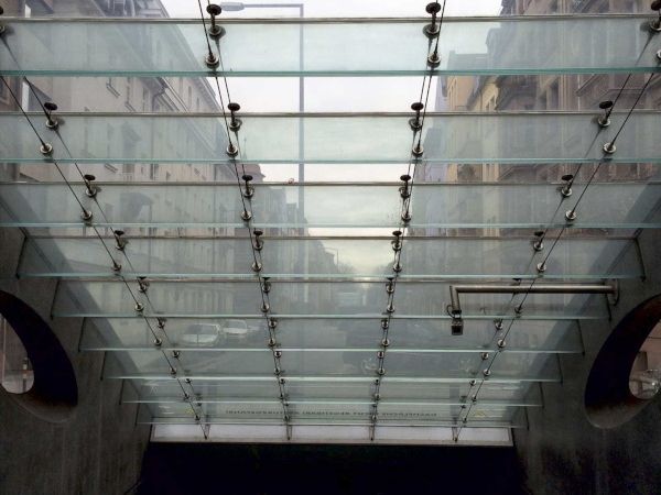
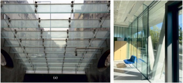
Building envelopes in entrance areas of public, retail or office buildings often exhibit a high transparency for a more aesthetic and inviting appearance. A maximization of the transparency can be achieved by using laminated glass beams or fins for the supporting structural elements (see examples in Fig. 1). From a structural point of view, laminated glass beams show brittle failure and have low residual load-carrying capacity after glass breakage. This latter characteristic is significantly lower than the load-carrying capacity before initial glass cracking, and depends on the type of glass and the stiffness of the interlayers used for lamination. To improve this aspect and to allow a ductile failure behaviour, previous research focused on adding tendons as reinforcement elements to laminated glass beams. In addition, such reinforcement also help to increase the initial glass cracking resistance of laminated glass beams, which can be even further improved by post-tensioning the beams through additionally pre-stressing the tendons. An overview of different reinforced and post-tensioned laminated glass beams investigated in recent research projects is provided by Martens et al. [1]. Compared to composite (or hybrid) glass beams, as described by Martens et al. [2], the cross-section share of the tendon material is relatively low for reinforced and post-tensioned glass beams, reaching values of maximum 10 %.
For the previously investigated reinforced laminated glass beams, tendons made of stainless steel or fibre reinforced polymers (FRP) were used. Either the tendons were bonded with adhesives to the edge of the laminated glass or they were embedded in the laminated glass cross section by recessing the middle glass layers. In the case of stainless steel tendons, rectangular or squared hollow sections (e.g., Louter [3], Louter et al. [4]) as well as strips or rectangular rods (e.g., Louter [3], Belis et al. [5], Olgaard et al. [6], Slivansky [7], Weller et al. [8]) were used. For FRP tendons, Palumbo et al. [9] used strips, Orlando et al. [10] round rods, Correia et al. [11] square rods, while Speranzini and Agnetti [12] used strips made of a steel reinforced polymer. Louter et al. [4] also investigated the influence of glass type (annealed glass, heat-strengthened glass, and fully tempered glass) on the structural behaviour of laminated glass beams with one-sided stainless steel reinforcement. It was shown that thermally tempered glasses allowed an increase of the pre-cracking load-carrying capacity for the same beam geometry, but annealed glass enabled a better post-breakage response with larger vertical displacements before ultimate failure and a similar post-cracking load-carrying capacity.
While for such reinforced laminated glass beams, the post-cracking load-carrying capacity is provided through the reinforcement in tension and a certain glass zone in compression, for laminated glass beams without a reinforcement, only the interlayer material is active in tension after glass cracking. Biolzi et al. [13] investigated the post-breakage response of laminated glass beams consisting of a middle annealed glass layer and exterior tempered glass layers, showing that stiffer ionoplast interlayers allowed for distributed crack development in the annealed glass layer and a higher stiffness of the partially damaged beams, compared to standard polyvinyl butyral (PVB) interlayers. For laminated glass beams consisting of fully tempered glass and ionoplast interlayers, Biolzi et al. [14] observed that in partially damaged laminated glass beams and fully damaged laminated glass beams, fragments of broken glass layers contributed to the post-breakage response through a tension stiffening effect of the interlayer. Galuppi and Royer-Carfagni [15] proposed a simplified analytical approach for predicting the post-breakage in-plane bending stiffness of fully damaged laminated glass beams made of fully tempered glass.
For post-tensioned laminated glass beams, steel or stainless steel rods were mostly used for the tendons in past investigations. The different systems can be differentiated in terms of the position of the rods – internally, at the edge of the glass beams (e.g., Bos et al. [16], Louter et al. [17], Louter et al. [18], Schober et al. [19]), or externally, outside of the beam cross section (e.g., Louter et al. [18], Engelmann and Weller [20], Jordao et al. [21]). In all of these situations, the tendons were pre-stressed mechanically – e.g. with hydraulic jacks – and anchored mechanically through steel parts at the ends of the laminated glass beams. Cupac et al. [22] used adhesive bonding for connecting and anchoring pre-stressed stainless steel strips to the glass edge. Moreover, Cupac et al. [23] proposed an analytical approach for determining the maximum allowable pre-load for such beams, while Cupac et al. [24] assessed the same concept for multi-span post-tensioned glass beams. Nevertheless, the pre-stressing of the tendons was still done mechanically before applying the adhesive, procedure that might be considered rather complex for practical applications.
Using iron-based shape memory alloys (Fe-SMAs) for the tendons is considered to allow a more easy-to-apply method for obtaining post-tensioned laminated glass beams with increased structural resistance, ductile failure behaviour and enhanced residual load-carrying capacity. Fe-SMAs proved to be feasible solutions for strengthening steel (e.g., Izadi et al. [25]) and concrete (e.g., Shahverdi et al. [26]) components retroactively. Related to applications of Fe-SMAs with glass, preliminary investigations dealing with identifying suitable adhesives and assessing an activation procedure of the Fe-SMA by electrical resistive heating were discussed by Silvestru et al. [27].
For glass beams supporting transparent roofs, as in Fig. 1a, where tension mostly occurs at the bottom edge because the self-weight compensates uplifting wind forces, adding tendons only along this edge is generally sufficient for reinforcement. Pre-stressing the one-sided tendons leads to precambering the beams. For glass fins supporting transparent facades, as in Fig. 1b, similar tensile stresses can occur at both glass beam edges due to alternating wind pressure and wind suction forces on the façade. In this case, adding reinforcement tendons along both glass beam edges makes sense, leading to a uniform pre-stress in the glass beam in case of post-tensioning. Recent research focused on monolithic [28] and laminated glass beams [29] reinforced and post-tensioned with Fe-SMA strips along a single edge.
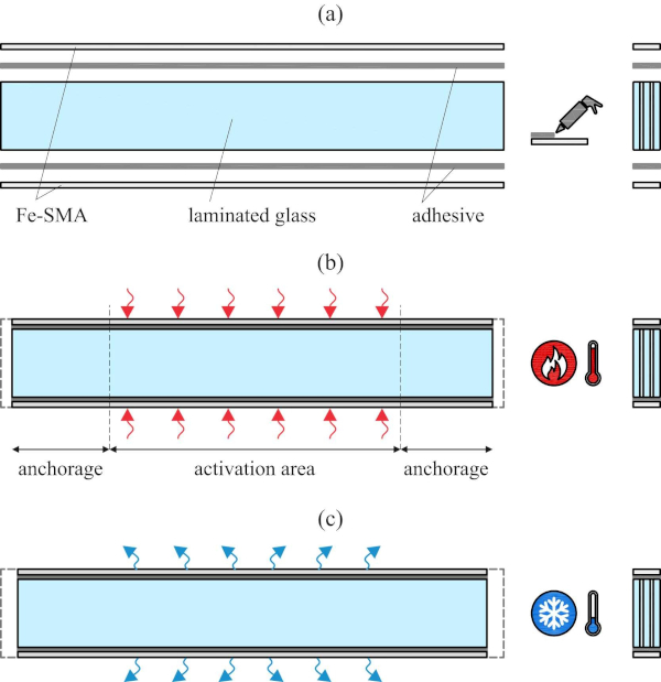
The results presented and discussed in the current paper deal with laminated glass beams reinforced and post-tensioned with Fe-SMA strips along both glass edges, as they would make sense for applications as supporting structural elements in transparent facades. Fig. 2 illustrates the investigated concept schematically. The Fe-SMA strips, which are previously pre-strained and cut into shape in the supplier’s workshop, are adhesively bonded to the edges of the laminated glass beams. After curing of the adhesive, the Fe-SMA strips are heated over a predefined activation length. This triggers the shape-memory effect in the Fe-SMA, leading to transformation of a certain fraction from the martensite induced during pre-straining back to austenite. The related effort of the strips to go back to their initial length before pre-straining is impeded by the anchorage, leading to a compressive pre-stress state in the laminated glass beam after cooling back to ambient temperature. More details on the Fe-SMA material are provided in Section 2.2, while the investigated adhesives are introduced in Section 2.3.
Preliminary results from experiments on reinforced and post-tensioned laminated glass beams with Fe-SMA strips adhesively bonded along both edges were presented by Silvestru et al. [30] for one selected adhesive. The investigations and results discussed in this paper significantly extend those preliminary results, analysing in detail and comparing the post-tensioning process and the structural performance of such reinforced and post-tensioned glass beams manufactured with two different adhesive types. Furthermore, an approach for predicting the pre-cracking and post-cracking structural behaviour of such beams by finite element simulations is introduced and validated. Investigations on predicting the pre-cracking and post-cracking structural behaviour of reinforced and post-tensioned laminated glass beams with stainless steel tendons were previously conducted by using different approaches for describing the cracking behaviour of glass. Bedon and Louter [31] used the “concrete damage plasticity” model available in the Abaqus/Standard [32] material library, while Bedon and Louter [33],[34] used the “brittle cracking” damage model within Abaqus/Explicit. Bedon and Louter [35],[36],[37] used the same approaches also for simulating the bending behaviour of post-tensioned structural glass beams with FRP tendons.
2. Materials
The structural elements investigated in this paper experimentally and numerically – i.e., (i) laminated glass beams without reinforcement, (ii) reinforced laminated glass beams and (iii) post-tensioned laminated glass beams – were composed of the laminated glass, and for the cases (ii) and (iii) of the iron-based shape memory alloy (Fe-SMA) strips and structural adhesives. Relevant characteristics of these different components and material properties are summarized in the next subsections, while the assumptions made for them in the finite element simulations are provided in Section 3.4.2.
2.1. Laminated glass
Laminated glass consists of two or more glass layers bonded together with polymer interlayers to obtain a sandwich-like structure. The main advantage of using laminated glass instead of monolithic glass cross-sections are given by the fact that in case of glass breakage, the resulting shards stick to the interlayer. On the one hand, this prevents injuries of persons near the glass, and, on the other hand, ensures a certain residual load-carrying capacity. For the investigated glass beams, the glass layers were made of annealed soda-lime-silica glass, while for the interlayers the ionoplast SentryGlas® was used. Annealed glass without thermal tempering was preferred due to its better performance in terms of residual load-carrying capacity of broken laminated glass and its lower price.
However, heat-strengthened glass would also be a suitable choice, having a higher strength and a similar failure mode. According to EN 572–1 [38], annealed glass has a Young’s modulus of 70,000 MPa, a characteristic bending strength of 45 MPa and a thermal shock resistance of 40 K. The properties of the interlayer ionoplast depend on load duration and temperature. Based on the product portfolio [39], a Young’s modulus of 493 MPa can be assumed for the displacement rate of 1 mm/min used in the tests and the recorded temperature of around 18 °C. More details on laminated glass, different glass types and properties of interlayer materials can be found in Haldimann et al. [40] and Schneider et al. [41].
2.2. Iron-based shape memory alloy (Fe-SMA) tendons
The iron-based shape memory alloy (Fe-SMA) used in this study was developed for applications in the construction field. As strips, it is available with a thickness of 1.5 mm and a width of 120 mm, and, generally, is used to retroactively pre-stress existing steel and concrete structures, due to its shape-remembering property. The Fe-SMA, which has an austenite structure after production (non-pre-strained), is generally pre-strained to 2.5 % in the production workshop, which leads to a first partial transformation to martensite. After being fixed to a parent structure, the Fe-SMA is heated to trigger the second transformation in which a share of the previously induced martensite transforms back to austenite. This couples with an effort of the strips to return to their initial shape (length), which is resisted by the anchorage to the parent structure leading to a pre-stress of this latter one.
For the anchorage bolts were mostly used for concrete and steel substrates, however, recently also adhesive bonding was assessed for steel beams by Wang et al. [42]. The second transformation is triggered starting with a temperature of around 50 °C, and the achieved pre-stress is increasing with higher targeted temperature. While for concrete and steel substrates different heating methods were applied (e.g., gas torch [43], infrared radiant heater, electrical resistive heating [44],[25]), for glass substrates, the electrical resistive heating method was preliminary assessed by Silvestru et al. [27]. The processes of pre-straining and activation by heating have an influence on the stress state within the Fe-SMA, as shown by the stress-strain and stress-temperature diagrams in Fig. 3a and Fig. 3b, respectively (adapted from Ghafoori et al. [45] and Izadi et al. [44]).
![Fig. 3. Qualitative (a) stress vs. strain and (b) stress vs. temperature behaviours of the bonded Fe-SMA strips during pre-straining and activation, and (c) representative uniaxial engineering stress vs. engineering strain relationship for non-pre-strained and pre-strained Fe-SMA. (diagrams adopted from [30]).](/sites/default/files/inline-images/Fig3_416.jpg)
Among others, Ghafoori et al. [45], Shahverdi et al. [43] and Silvestru et al. [46] investigated previously the material behaviour of the Fe-SMA in strip form. In this paper, the behaviour of the Fe-SMA is assumed according to the results in Silvestru et al. [46], which in case of the pre-strained material were obtained from uniaxial tensile tests on strips made from the same batch as the strips used for the reinforced and post-tensioned glass beams. The stress versus strain relationships of the pre-strained and non-pre-strained Fe-SMA are shown in Fig. 3c. The Young’s modulus of the Fe-SMA is around 170,000 MPa, it reaches an ultimate strength of almost 1000 MPa and elongations at break of over 30 %. Silvestru et al. [46] also showed the suitability of the two-stage Ramberg-Osgood model to determine stress-strain data that reproduce the uniaxial tensile behaviour of the pre-strained and the non-pre-strained Fe-SMA.
2.3. Structural adhesives
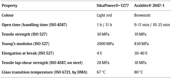
Two different structural adhesives were used for bonding the Fe-SMA strips to the laminated glass edges in case of the reinforced and the post-tensioned laminated glass beams – the two-component epoxy SikaPower®− 1277 and the two-component methacrylate Araldite® 2047–1. Selected relevant properties as found in the technical datasheets ([47], [48]) are provided in Table 1. These adhesives were chosen based on their previous use in research projects with Fe-SMA and glass as substrate materials, as well as based on their preliminary assessment in Silvestru et al. [27] for shear joints between Fe-SMA strips bonded to glass plates.
Table 1. Selected relevant properties of the applied two-component structural adhesives: the epoxy SikaPower®−1277 [47] and the methacrylate Araldite® 2047–1 [48].
The epoxy showed a good behaviour in shear connections between Fe-SMA and steel investigated by Wang et al. [49] and Wang et al. [50], while Cardoso et al. [51] characterized its strength and fracture behaviour based on experiments. Moreover, Li et al. [52] investigated the debonding behaviour of Fe-SMA-to-steel shear joints with the epoxy, and Li et al. [53] analysed the influence of activation temperature and pre-stress on the behaviour of the same type of joints. Deng et al. [54] investigated the performance of shear joints between Fe-SMA strips and glass plates for different joint dimensions and Deng et al. [55] for different temperatures. The methacrylate was applied previously in several research projects on structural components with linear adhesive joints between glass and metal components. Nhamoinesu et al. [56] and Pascual et al. [57] investigated steel-glass composite panels with hollow-section steel profiles bonded to the glass surface, while Cupac et al. [22] used the methacrylate in post-tensioned laminated glass beams with stainless steel tendons adhesively bonded at the glass edge. Moreover, Katsivalis et al. [58] conducted an experimental and numerical study on glass-steel shear joints with the methacrylate.
3. Methods
3.1. Specimen types and manufacturing of reinforced laminated glass beams
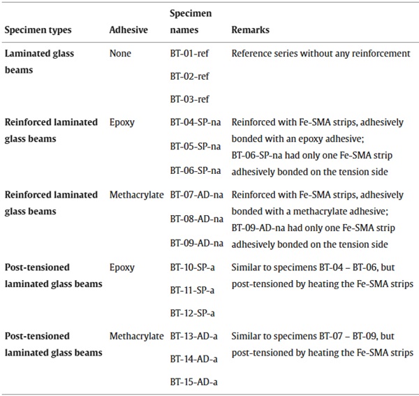
The experimental program included fifteen specimens, as listed in Table 2. Three specimens were laminated glass beams without reinforcement, used as reference. The other twelve specimens were reinforced with adhesively bonded pre-strained Fe-SMA strips along both edges. For six of them, the epoxy adhesive and for the other six the methacrylate adhesive were used. For three reinforced laminated glass beams with each of the two adhesives, the Fe-SMA tendons were activated to obtain post-tensioned laminated glass beams.
Table 2. Overview of the different glass beam types investigated experimentally and numerically in four-point-bending.
The geometries of the beams are illustrated for the laminated glass beams in Fig. 4a, and for the reinforced and the post-tensioned laminated glass beams in Fig. 4b, respectively. The laminated glass beams consisted of three annealed glass layers, a middle one with a thickness of 10 mm and the two exterior ones with thicknesses of 6 mm each. The three glass layers were laminated together with two SentryGlas® interlayers with thicknesses of 1.52 mm each. The laminated glass beams had a length of 1500 mm and a height of 122 mm. These dimensions were chosen to be in agreement with those used by Cupac et al. [22] to allow an eventual comparison of the results. For the reinforced and the post-tensioned beams, 1.5 mm thick pre-strained Fe-SMA strips were adhesively bonded to the edges of laminated glass beams with dimensions as described before. The strips had the same length as the glass beams, a width of 25 mm corresponding to the total laminated glass beam thickness, and were sandblasted before being bonded. The adhesive joints extending over the whole length and width of the Fe-SMA strips had a thickness of 1.5 mm for both applied adhesive types.
![Fig. 4. Specimen geometry and location of measurement instrumentation (strain gauges and thermocouples) for (a) the laminated glass beams and (b) the post-tensioned laminated glass beams (same geometry also for reinforced beams). (sketches adapted from [30]).](/sites/default/files/inline-images/Fig4_401.jpg)
The adhesive bonding of the two Fe-SMA strips of each specimen was done in subsequent steps at a time difference of one day. Tapes and Teflon spacers with a width of 10 mm were used to cleanly delimit the joint width and to ensure the joint thickness, respectively. The position of the spacers is visible in Fig. 4b. Acetone was used to clean the glass edge and Fe-SMA surfaces before applying the adhesives. In the case of the methacrylate, the glass surfaces were additionally treated with a primer (3 M VHB Silane Glas Primer). The epoxy adhesive was applied on both the glass edge and Fe-SMA surfaces in the form of a caterpillar with a conventional hand application gun from 195 ml dual cartridges equipped with static mixers. For the methacrylate, a similar application procedure was used with a DM2×10:1 400–10-60–01 manual dual gun from 480 ml dual cartridges. The adhesives were tooled with a spatula on both surfaces to ensure a uniform distribution, and then the Fe-SMA strip was pressed against the glass edge, having the thickness-ensuring spacers between them. The bond-delimiting tapes were removed after a few minutes and the specimens were left to cure for at least 24 h with weights on the Fe-SMA strips, before turning them upside down and repeating all the steps for the second Fe-SMA strip. Before the next step of applying strain gauges and thermocouples on the specimens, the beams were stored in a climate chamber at 20 °C and 50 % relative humidity for two weeks.
Strain gauges were applied on all experimentally investigated glass beams in their middle as follows. In case of the laminated and the reinforced laminated glass beams, one strain gauge (SG01) was applied on the front glass surface 5 mm below the top glass edge, and another two strain gauges (SG03 & SG04) were applied on the front and on the back glass surface, respectively, 5 mm above the bottom glass edge. For the post-tensioned glass beams, an additional strain gauge (SG02) was applied on the front glass surface at mid-height, while for both the reinforced and the post-tensioned glass beam, two more strain gauges were applied in the middle of the Fe-SMA strips – one on the top strip (SG05) and one on the bottom one (SG06). In case of the post-tensioned beams, the gauges on the strips were only applied after activation to avoid them being damaged during this process. The post-tensioned glass beams were additionally equipped before activation of the Fe-SMA strips (before post-tensioning) with fourteen thermocouples of type K each, positioned at different locations on the glass surfaces and on the strips. Fig. 4 illustrates the position of all the strain gauges and thermocouples.
3.2. Post-tensioning by electrical resistive heating of Fe-SMA tendons
The post-tensioning of the test specimens BT-10 to BT-15 was performed by heating the adhesively bonded pre-strained Fe-SMA strips over a pre-defined activation length of 850 mm. Electrical resistive heating was used, a procedure in which an electric current is applied to the Fe-SMA allowing to target specific temperatures in the activation area, without heating the anchorage areas. In case of using adhesive joints for the anchorage, this is essential to avoid damaging the adhesive in these areas. Previous applications of this procedure with steel substrates can be found in Izadi et al. [44] and Izadi et al. [25], while Silvestru et al. [27] preliminary assessed the method for glass substrates. Fig. 5 illustrates the setup used for post-tensioning the reinforced laminated glass beams investigated in this paper. A single circuit was used for applying the current, which was introduced to the top strip and discharged from the bottom strip on the same side, while it was diverted from the top to the bottom strip on the other side.
Copper clamps were used for introducing, diverting and discharging the current. Their positions, 325 mm away from the beam ends, are visible in Fig. 5 and are dimensioned in Fig. 4b. The lengths of the anchorage areas were chosen based on the lap-shear tests and the preliminary activation investigations in Silvestru et al. [27]. During post-tensioning, Teflon layers were used at the supports of the beams to allow sliding. For activation, an electrical power supply unit provided by the Fe-SMA producer was used to apply an amperage of 200 A until a temperature of 160 °C was reached in one of the Fe-SMA strips. The temperature, which was chosen based on the preliminary study in Silvestru et al. [27] to avoid too much heating of the adhesive (eventually leading to softening and debonding) and the glass (eventually leading to thermal shock) in the activation area, was measured at different points with thermocouples.

3.3. Four-point bending tests
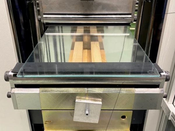
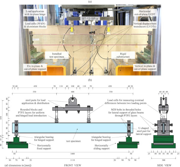
Four-point bending tests were performed on a servo-hydraulic Schenck testing machine at room ambient temperature of around 18 °C. The primary objective of the tests was to quantify the improvement in initial glass crack resistance and residual load-carrying capacity by reinforcing the laminated glass beams with adhesively bonded Fe-SMA strips as well as by additionally post-tensioning them. Fig. 6a shows the test setup and its main components before testing of a specimen. Fig. 6b provides the main dimensions of the test setup as well as a more detailed description of the parts used for load application and support of the beams. The load was applied under displacement control with a load-distributing beam, hinged-connected to the testing machine. An initial displacement rate of 1 mm/min was used. After reaching a vertical traverse displacement of 15 mm, the displacement rate was increased to 2 mm/min until 45 mm and to 4 mm/min until the end of the tests.
The distance between the load application points was 400 mm. Two half-cylindrical steel parts and aluminium blocks with additional 3 mm thick PTFE layers were used at the load application points. In addition to the load cell of the testing machine, two 50 kN load cells were used to measure the two point loads and capture an eventual non-uniform loading, especially in the post-cracking phase. The distance between the supports was 1400 mm. Two fork-shaped steel parts were used to restrain the vertical in-plane and the horizontal out-of-plane translations as well as the rotation around the longitudinal beam axis. The steel parts were positioned on bearing elements with horizontal triangular steel rods oriented perpendicular to the longitudinal glass beam axis.
This allowed rotations around the axis of the triangular rods. PTFE layers with a thickness of 3 mm were used between the specimens and the fork-shaped support parts to avoid direct contact between steel and glass. The glass beams were simply supported, the bearing element on the left being fixed, while the one on the right allowing horizontal sliding in longitudinal direction. The vertical displacement of the beam was measured at midpoint and below the load application points with linear variable differential transformers (LVDTs). An additional LVDT was used to measure the horizontal out-of-plane displacement at the midpoint of the top beam edge. This displacement was found to be negligible, which indicated that lateral torsional buckling was not an issue for the chosen setup and specimen configurations. Frontal pictures of the specimens were taken during testing every 30 s to capture the crack pattern development.
3.4. Finite element simulations
3.4.1. General finite element model features
Finite element simulations of the experimentally investigated glass beam types were conducted with the computer-aided engineering software Abaqus [32] to validate a model that can be used for investigating further parameters and configurations. Assumptions made by Bedon and Louter [33] and by Bedon and Louter [34] where used when developing the model. The explicit solver was used with careful attention that the simulation behaved as under quasi-static loading to be in agreement with the experimental conditions. The model used for the simulations, including the mesh density, the boundary conditions and the load application, is shown in Fig. 7. A swept mesh with a smaller element size of 2.5 mm along the bottom beam edge and a larger element size of 10 mm along the top beam edge was chosen. Considering the location of crack initiation at the bottom side of the glass beams and the distribution of cracks during the physical tests, this swept mesh pattern allowed a better capture of glass crack initiation and propagation in the simulations.
Both the glass layers and the interlayers had one element in thickness direction. This was sufficient for the investigated glass beams, since no loading or deformation occurred in out-of-plane direction. 8-node linear brick elements with reduced integration (C3D8R) were used for all components included in the model based on their previous good performance for similar tasks in [33] and [34]. Quadratic brick elements were considered initially, but would have significantly increased the computation time, which already averaged two-three days with 128 CPUs for the post-tensioned laminated glass beams modelled with linear elements. In addition, also a non-swept regular mesh with the smaller element size of 2.5 mm, or an even finer mesh would not have been feasible in terms of computation time. Coarser regular or swept mesh patterns were considered, but proved unsuitable for reproducing similar crack patterns to those from the physical tests.
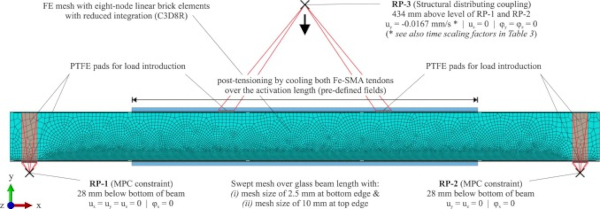
The model included the glass layers and the interlayers of the laminated glass, the adhesive, the Fe-SMA tendons and Teflon (PTFE) layers at the support and loading points. The glass layers were connected to the interlayers with tie constraints. The same type of constraint was used between the glass edges and the adhesive as well as between the Fe-SMA surfaces and the adhesives, assuming that a loss of adhesion would not occur at an early stage of the tests. Moreover, the Teflon pads used for load application and support were as well tied to the respective Fe-SMA and glass surfaces, since no relative sliding was observed in these areas (horizontal sliding of the free right support occurred in the support element, which was considered in the applied boundary conditions). This also allowed better convergence and shorter computation times. The boundary conditions and the load were applied on reference points. The reference points for the boundary conditions (see RP-1 and RP-2 in Fig. 7) were situated at a distance of 1400 mm between them and 28 mm below the bottom of the beam, corresponding to the tip of the triangular rods in the test setup. The two reference points were connected to the exterior Teflon surfaces with multi-point constraints. The reference point for load application (see RP-3 in Fig. 7) was situated 434 mm above the support reference points, corresponding to the position of the hinge in the test configuration.
For the laminated glass beams without reinforcement and the reinforced laminated glass beams, only the four-point bending was simulated. For the post-tensioned laminated glass beams, an additional step simulating the activation of the Fe-SMA tendons was included. This latter one was done by modelling a cooling of the Fe-SMA tendons over the activation length of 850 mm. This was done through predefined fields, a first one in which all components had a temperature of 0 °C and a second one, in which the tendons were cooled down by 90 °C over the length mentioned before. This temperature was chosen for obtaining an approximately similar compressive pre-stress in the glass as achieved in the experiments according to the strain gauge measurements.
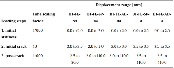
The load for the four-point bending was applied as a displacement rate of −0.0167 m/s, which corresponded to the initial rate of 1 mm/min used in the tests. However, the four-point bending was divided into several steps in the simulations and additional time scaling factors were used to reduce the necessary computation time. For the first loading step in the linear elastic range before the first glass crack occurred, a time scaling factor of 1000 was used. In the displacement range in which the first glass crack was expected, a second loading step with a reduced time scaling factor of 10 was used, in order to avoid significant dynamic effects in the moment of the initial crack. After this range of vertical displacement, a third loading step with an increased time scaling factor of 1000 was simulated to reduce the total computational time. In preliminary simulations, it was observed, that the dynamic effects (based on the ratio between kinetic energy and total internal energy of less than 5 %) were lower for subsequent cracks, and therefore this increase of the time scaling factor was considered acceptable. A performed sensitivity analysis for the time scaling factor showed that lower factors would lead to unfeasible computation times, while higher scaling factors would lead to dynamic effects visible as force drops down to even negative values. The different displacement ranges for the three steps in the case of the five different glass beam types are provided in Table 3. A smooth step procedure was used for the transition between the different steps.
Table 3. Displacement ranges for the applied loading steps with different time scaling factors in the case of the five different simulated glass beam types.
3.4.2. Definition of material properties
Table 4 gives an overview of the elastic and plastic material properties used for the different materials included in the models. Except for glass, for all other materials plastic properties were defined in addition to the elastic ones. Moreover, density values were necessary due to using the explicit solver, and thermal expansion coefficients due to the cooling step for simulating the post-tensioning. The assumption of an elastic-plastic material model for the interlayer is a simplification valid for the conditions under which the experiments and the simulations were performed – constant temperature and quasi-static constant loading. For applying the model under different temperature and loading conditions, the material properties of the interlayer would need to be adapted, either by using different stiffness values or, more appropriate, by using a viscoelastic model, e.g., based on temperature and strain-rate dependant stress-strain curves, as described by Santarsiero et al. [59]. The plastic properties of the Fe-SMA are provided in Table 5 and were derived from uniaxial tensile test data based on the Ramberg-Osgood model, as described by Silvestru et al. [46]. Considering the method used for modelling the post-tensioning, the pre-strained Fe-SMA properties were attributed to a temperature of 0 °C and the non-pre-strained Fe-SMA properties to a temperature of −90 °C.
Table 4. Material properties as used for input in the finite element model.
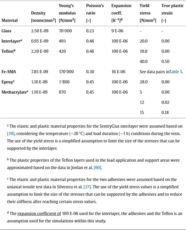
Table 5. True stress vs. true plastic strain data pairs used as input for the plastic behaviour of the iron-based shape memory alloy.
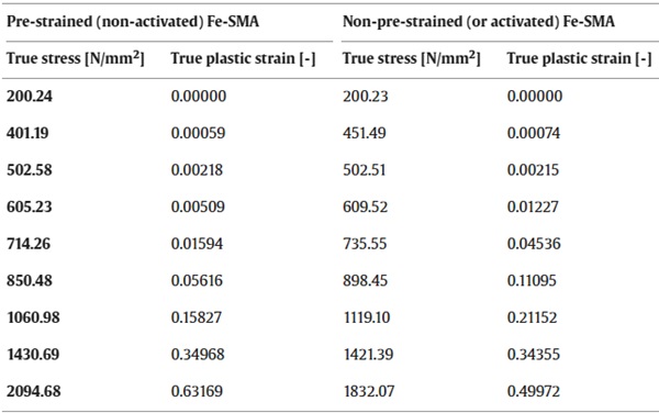
To predict the glass cracking and hereby the post-cracking behaviour of the glass beams, the brittle cracking model from the Abaqus library with its options “brittle shear” and “brittle failure” was used. The parameters required by this model were chosen in agreement with those used by Bedon and Louter [34]. The mode I fracture energy of Gf = 3 J/m2 was used for all investigated beam types. The tensile failure stress σtk was defined based on the strain measured during the tests near the bottom glass beam edge just before the initial crack occurred. The values used for the different investigated glass beam types are given in Table 6. The differences are attributed to the adhesive joints, which delay the initial crack and impede the micro-flaws to grow.
Table 6. Tensile failure stress and failure displacement used for the different investigated glass beam types.

The “brittle shear” option describes the behaviour of the glass after cracking, by estimating the shear modulus of the cracked glass Gc,glass as a ratio of the shear modulus of the glass without cracks Gglass, according to Eq. (1), where ε ₙₙᶜᵏ is the actual strain and εₘₐₓᶜᵏ is the ultimate crack opening strain. The required parameter p and the ultimate crack opening strain εₘₐₓᶜᵏ were assumed equal to 5 and 0.005, respectively, according to Bedon and Louter [34]. The option “brittle failure” defines a failure displacement at which elements are assumed as cracked and are removed from the mesh. The failure displacement uck depends on the failure stress σtk and the fracture energy Gf and can be calculated by Eq. (2). The values used for the different investigated glass beam types are provided in Table 6.

4. Results and discussion
The results are presented and discussed in two parts: first, for the post-tensioning step in Section 4.1, and second, for the four-point bending step in Section 4.2. Both parts include experimental and simulation results, allowing to discuss the results separately as well as to compare them to each other.
4.1. Post-tensioning results and related observations
For post-tensioning the laminated glass beams, the adhesively bonded Fe-SMA strips were heated over a pre-defined activation length by electrical resistive heating. The process was monitored by temperature and strain measurements over a period of two hours. The diagrams in Fig. 8 show these measurements for one representative specimen with the epoxy adhesive (BT-12-SP-a) and one with the methacrylate adhesive (BT-13-AD-a). In Fig. 8a and Fig. 8b, average temperature values are plotted for the thermocouples applied in different areas of the Fe-SMA strips and glass surfaces. Fig. 8c and Fig. 8d show the strains measured on the glass surfaces in different points at mid-length of the beams. The curves for the thermocouples applied on the Fe-SMA strips outside the activation area, TC (01;04;05;08), show that no increase in temperature occurred along the anchorage length. This was in agreement with the desired circuit for current flow and ensured that the adhesive was not heated and damaged along the anchorage length.
A comparison between the temperatures reached in the two strips of the same beam shows that the top Fe-SMA strip, TC (02;03), heated slightly more than the bottom one, TC (06;07). This was in agreement with the higher maximum strains reached in the glass near the top edge (SG01) compared to those near the bottom edge (SG03 and SG04). The maximum increase in temperature of the glass did not exceed 20 °C near the glass beam edges, TC (09;11), and was significantly less at mid-height of the beams, TC (10;12;13;14). In terms of strains in the glass, high values were reached near the Fe-SMA strips at the beginning of the activation procedure. The values differed both between top (SG01) and bottom edge (SG03 and SG04), and between front (SG03) and back (SG04) of the beams. The different strains in the front and back glass layers might have resulted because of discrepancies in the adhesive joint over its width or because of non-uniform pre-strain recovery during activation of the Fe-SMA strips over their width (the 25 mm wide Fe-SMA strips were cut in longitudinal direction from 120 mm wide pre-strained strips). At the end of the two hours of monitoring, however, all measured strains were in the same range of around 80–100 µm/m.
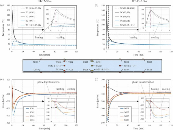
Fig. 8 includes zoom-in diagrams for the first three minutes of the activation process. These diagrams show that until reaching a temperature of around 45–50 °C on the Fe-SMA strips, tensile strains were measured on the glass with all four strain gauges. Only after reaching this temperature, the transformation process from martensite back to austenite was triggered in the Fe-SMA, leading to its effort to go back to its initial non-pre-strained shape and implicitly to inducing compressive strains to the glass.
For a better quantitative assessment and comparison of the results for the post-tensioning process in the case of the beams with the two different adhesives, Table 7 provides selected parameters as average values from the three similar specimens. Based on the strain in glass after 120 min, εglass,120 min, and the Young’s modulus of glass, Eglass = 70,000 MPa, the stress in the glass after post-tensioning, σglass,120 min, was determined with Eq. (3). For the strain in the glass after 120 min, the average of the values measured with the four strain gauges per specimen was used. By assuming equilibrium after all materials cooled back to room ambient temperature, the stress in the Fe-SMA strips, σFe-SMA,120 min, was determined with Eq. (4), where AFe-SMA was the surface of one Fe-SMA strip and Aglass was the total surface of the three glass layers in the laminated glass beams. The average values determined for the post-tensioned glass beams did not show significant differences depending on the different adhesives used for bonding the Fe-SMA strips. For all beams, the targeted heating temperature of 160 °C resulted in a compressive pre-stress of almost 7 MPa in the glass beams.

Table 7. Results from the temperature and strain measurements during activation of the Fe-SMA by electrical resistive heating (average values from the beams with epoxy adhesive and those with methacrylate adhesive).
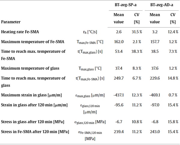
In the finite element simulations, the post-tensioning was modelled by cooling down the Fe-SMA strips over the defined activation length by 90 °C. This resulted in stresses in longitudinal beam direction of 7.5 MPa in the middle glass layer, 6.0 MPa in the exterior glass layers and 228.3 MPa in the Fe-SMA strips for the simulation with the epoxy adhesive (BT-FE-SP-a). For the simulation with the methacrylate adhesive (BT-FE-AD-a), the resulting stresses in longitudinal beam direction after post-tensioning were 7.1 MPa in the middle glass layer, 6.1 MPa in the exterior glass layers and 225.5 MPa in the Fe-SMA. These were in relatively good agreement with the values calculated based on the strain measurements. The stress distributions in the middle glass layer and one of the exterior glass layers after post-tensioning are shown for the simulations with the two different adhesives in Fig. 9. By comparing the results obtained with the different adhesives, higher stress peaks could be observed at the interior ends of the anchorage areas in the case of the stiffer and more brittle epoxy.

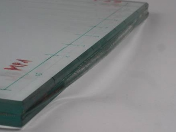
Certain issues were experienced during activation for the specimens with epoxy adhesive, which should be avoided in case of future developments of the post-tensioned glass beams with adhesively bonded Fe-SMA strips. The image in Fig. 10a illustrates that for the specimens with epoxy adhesive, shear cracks and debonding of the adhesive from the glass edge were observed. This was not the case for the more ductile methacrylate adhesive. The shear cracks occurred because of unfortunate positioning of the copper clamps on the interior of the spacer gaps, leaving only a short length of adhesive joint before the gap for transferring the occurring shear forces. The debonding occurred due to softening of the adhesive during heating. Although this did not have a negative influence on the structural performance of the beams in the four-point-bending tests, it needs to be prevented due to aesthetical reasons.
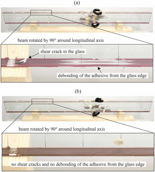
By optimizing the manufacturing and post-tensioning procedure, issues like those shown in Fig. 10 in the case of the epoxy adhesive could be prevented. One option would be to apply the adhesive before activation only in the anchorage areas and to add it in the gap between strips and glass edge along the activation length only after activation. This would prevent softening and debonding of the adhesive in the activation area during heating. Moreover, by placing the copper clamps just outside the spacer gaps instead of inside them, shear cracks, as experienced for some specimens with epoxy adhesive could be avoided. The achieved pre-stress for the glass beams investigated in this paper of 7 MPa corresponds to around 15 % of the characteristic tensile strength of annealed glass of 45 MPa.
However, considering that the targeted heating temperature of 160 °C for the Fe-SMA only led to a small temperature increase in the glass, along with the procedure optimizing measures mentioned before regarding adhesive application, higher pre-stress levels are expected to be possible with higher targeted heating temperature. For strengthening concrete or steel structures, mechanically fixed Fe-SMA strips are generally heated to 300–350 °C during activation. Moreover, if the Fe-SMA will be available in the future in other thicknesses than the current 1.5 mm, also increased cross-section shares of the Fe-SMA could be used to achieve higher pre-stress levels.
4.2. Four-point bending behaviour
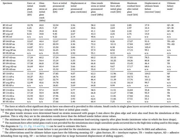
The different types of glass beams were investigated in four-point bending both experimentally and by finite element simulations. In this section, the results are presented and discussed for the different types of glass beams – laminated glass beams without reinforcement, reinforced laminated glass beams, and post-tensioned laminated glass beams – based on force vs. displacement diagrams and fracture patterns. In section 5, the contribution of the Fe-SMA strip reinforcement and of the post-tensioning to the initial bending stiffness, the initial fracture resistance, the post-fracture behaviour and the ultimate failure are discussed. In addition, selected quantitative values from tests and simulations are provided in Table 8 for better variation assessment of experimental results and comparison to simulation results.
4.2.1. Laminated glass beams without reinforcement
Fig. 11 shows the force vs. vertical displacement curves of the laminated glass beams from the tests (greyscale curves) and from the simulation (red curve). The diagram in Fig. 11a shows a displacement range of 110 mm chosen to cover the maximum vertical displacement recorded for the reinforced and the post-tensioned beams in the tests. The diagram in Fig. 11b shows a displacement range of 8 mm to better illustrate the behaviour before and just after the initial glass crack resistance. The same type of diagrams are used for the reinforced beams in Fig. 13 and for the post-tensioned beams in Fig. 16. Fig. 12 shows the crack patterns for a representative laminated glass beam captured during the four-point bending test and obtained from the corresponding simulation just after occurrence of the initial pronounced glass crack (a) and after 20 mm vertical displacement (b).

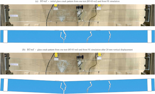
From the experimentally obtained curves in Fig. 11, it can be observed that the initial pronounced glass crack led to a significant drop in bearable force. Afterwards, only the tensile resistance of the interlayer in the bottom part of the beam and the compressive resistance of the broken glass in the top part of the beam provided the low residual load-carrying capacity. The force, at which the initial pronounced glass crack occurred, varied significantly between the three tested laminated glass beams (see also values in Table 8). This variation was attributed solely to the scattering of the glass edge strength, which depends on the size and depth of flaws present at the glass edge, despite grinding or polishing after cutting. Moreover, it should be considered that all the specimens were tested under the same conditions and had similar cross-section dimensions. Therefore, the higher bearable force reached by specimen BT-01-ref suggested that the glass layers of this specimen had less pronounced flaws at their bottom edge.
The curve obtained from the simulation was in relatively good agreement with the average of the experimental curves in terms of initial bending stiffness and initial glass crack resistance. The worse agreement for the post-fracture behaviour was because in the simulation, elements that reached the defined glass tensile failure stress were removed from the model, while in the tests the broken glass shards were still present, allowing for transferring compressive forces near the top edge of the beams. An additional simulation was carried out for the laminated glass beams without removing the elements that reached the defined glass tensile failure (BT-FE-ref* with orange curve in Fig. 11). This helped to avoid the force drop to zero after the initial pronounced glass crack, but did not allow illustrating the crack development, and resulted in more pronounced dynamic effects in the explicit simulations that eventually led to unstable behaviour (force drop to zero after 12.5 mm).
For the reinforced and post-tensioned glass beams, only the simulations with removing the elements that reached the defined tensile failure stress were conducted, due to the above reasons. In addition, for those specimens, the initial pronounced glass crack in the simulations did not extend over the entire laminated glass cross-section height. Hereby, a certain glass cross section near the top edge remained intact and allowed for transferring compressive forces over the entire post-breakage displacement range in the case of the reinforced and post-tensioned glass beams (see sections 4.2.2 and 4.2.3). The ultimate failure in the tests occurred when the tensile strength of the interlayer was reached in the area where the initial pronounced glass crack occurred. This is visible from the images of the test specimen shown in Fig. 12. It can as well be observed that in the tests only one pronounced glass crack occurred, which then expanded until ultimate failure. The cracking behaviour and pattern was reproduced relatively well by the simulation.
4.2.2. Reinforced laminated glass beams
Fig. 13 shows the force vs. vertical displacement curves from experiments and simulations of reinforced laminated glass beams with epoxy adhesive (a & b) and with methacrylate adhesive (c & d). Fig. 14 and Fig. 15 show the crack patterns after the initial pronounced glass crack (a), after 20 mm vertical displacement (b) and after the displacement at which failure occurred in the tests (c) for a representative reinforced laminated glass beam with epoxy adhesive and with methacrylate adhesive, respectively. As in case of the laminated glass beams, the initial pronounced glass crack led to a force drop. However, this occurred at higher forces compared to the beams without reinforcement, an average increase of 72 % being achieved with the epoxy adhesive and of 77 % with the methacrylate adhesive. It should, however, be noticed that a higher variation of the force at initial pronounced glass crack was observed for the specimens with epoxy adhesive compared to those with methacrylate adhesive (see values in Table 8).
This variation could be partially attributed to the scattering of the glass edge strength, as in the case of the laminated glass beams. However, for the specimen BT-05-SP-na, the slightly wider Fe-SMA strip bonded at the bottom edge, with 25.0 mm compared to 24.6 mm for the other two specimens, also provided a contribution to the higher reached force. The values to which the force dropped were significantly higher than for the beams without reinforcement. In average, values of 8.92 kN were reached for the beams with epoxy adhesive and of 9.67 kN for those with methacrylate adhesive, while for the beam without reinforcement, values of 2.25 kN were recorded. The differences were even larger in terms of residual load-carrying capacity. While the beams without reinforcement reached only a maximum force of 2.75 kN in average, the reinforced beams reached 17.15 kN when using the epoxy adhesive and 17.17 kN when using the methacrylate adhesive, respectively.
These values were in average even slightly higher than those at which the initial pronounced glass crack occurred. These aspects are also visible in the diagrams from Fig. 13. This high residual load-carrying capacity was ensured by the tensile resistance of the Fe-SMA strip in the bottom part of the beam and the compressive resistance of a non-cracked glass zone in the top part of the beam. The diagrams in Fig. 13 also show that the simulations performed for these types of beams allowed a good prediction of the force vs. displacement behaviour, both before initial pronounced glass crack and in the post-cracking range. The pronounced spikes going upwards and downwards in the post-cracking range of the curves obtained from the simulations were due to the high time-scaling factor (1000) and can be disregarded. In addition, the fact that the force drop after the initial pronounced glass crack was higher in the simulation curves compared to the experimental ones is due to the time scaling of 10 used for this part of the simulation.
Both from the curves in Fig. 13 and from the crack patterns in Fig. 14 and Fig. 15, it can be observed that the reinforced beam specimens with epoxy adhesive exhibited a higher number of cracks compared to those with methacrylate adhesive. This was due to the more ductile behaviour of the methacrylate. It is to be specified that the models did not include damage criteria for the Fe-SMA tendons, the adhesives, or the interlayer. Therefore, the ultimate failure of the specimens due to rupture of the tendons is not visible in the simulation results. An approximate estimation of the moment of ultimate failure could eventually be made by reading the stress in the tendon and compare it with the uniaxial tensile stress-strain relationship of the Fe-SMA.
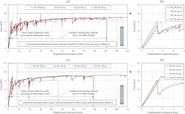
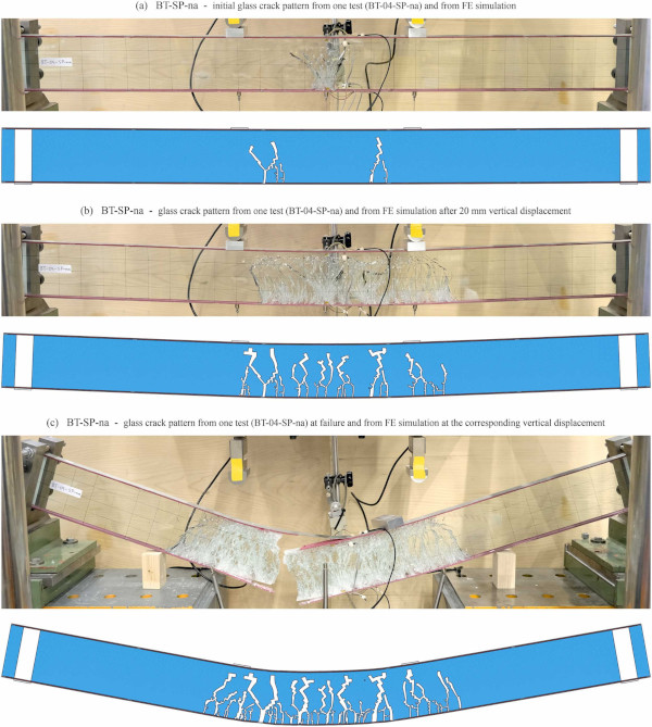
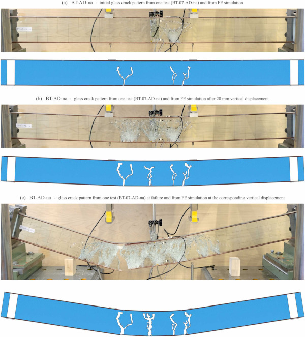
The crack patterns were reproduced relatively well by the simulations, especially in the case of the specimens with epoxy adhesive. The observed ultimate failure modes were either tendon rupture alone or tendon rupture coupled with a debonding of the adhesive from the top Fe-SMA strip in case of specimens with epoxy adhesive. For specimens with methacrylate adhesive, tendon rupture alone was observed for two specimens, while for the third the test was stopped before ultimate failure occurred. In average, the specimens with methacrylate adhesive reached lower displacements at ultimate failure.
4.2.3. Post-tensioned laminated glass beams
The force vs. vertical displacement curves from experiments and simulations of post-tensioned laminated glass beams with epoxy adhesive (a & b) and with methacrylate adhesive (c & d) are shown in Fig. 16. The post-tensioning led to a further increase of the forces at initial pronounced glass crack compared to the reinforced laminated glass beams. In comparison to the laminated glass beams without reinforcement, the average increase was 109 % for the specimen with epoxy adhesive and 89 % for those with methacrylate adhesive. This confirmed that the post-tensioning of laminated glass beams with adhesively bonded Fe-SMA strips activated by electrical resistive heating allowed achieving the objective of increasing the initial load-carrying capacity. A slight increase compared to the reinforced glass beams was also observed for the value to which the force dropped after the initial pronounced glass crack and for the maximum force reached in the post-cracking range. The exact values can be found in Table 8. The high residual load-carrying capacity was ensured also in this case by the tensile resistance of the Fe-SMA strip in the bottom part of the beam and the compressive resistance of a non-cracked glass zone in the top part of the beam.
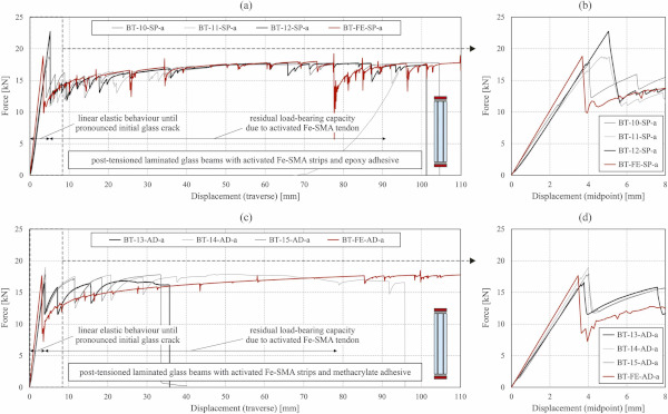
The performed simulations for the post-tensioned laminated glass beams allowed a relatively good prediction of the force vs. displacement relationships according to the diagrams in Fig. 16. However, in case of the specimens with the methacrylate adhesive, this was not as good as in case of the reinforced glass beams. This might be due to the assumptions made for the different materials (e.g., adhesive might have behaved differently after being heated and cooled during activation). Fig. 17 and Fig. 18 show the crack patterns after initial pronounced glass crack (a), after 20 mm vertical displacement (b), and after the displacement at which failure occurred in the tests (c) for a representative post-tensioned laminated glass beam with epoxy adhesive and with methacrylate adhesive, respectively, as well as from the corresponding simulations. The results from the simulations reproduced well the experimentally observed patterns for the specimens with methacrylate adhesive (see Fig. 18), but resulted in less cracks for the specimens with epoxy adhesive. A possible explanation for this might be an assumed too high tensile failure stress in this case, although this was done based on measured strains in the experiments.
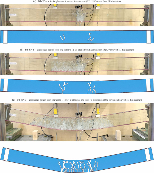
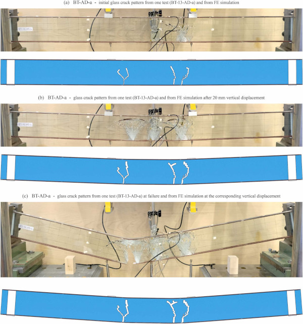
The observation that the specimens with epoxy adhesive exhibited more cracks than the specimens with methacrylate adhesive, which was already made for the reinforced glass beams, was also valid in the case of the post-tensioned ones. In case of the post-tensioned beams with epoxy adhesive, no ultimate failure was reached in the tests, because they were stopped due to too large horizontal displacements at the sliding support. For the specimens with methacrylate adhesive, all specimens exhibited an ultimate failure due to tendon rupture. The displacements at which these failures occurred were in average significantly lower than those at which the tests were stopped for the specimens with epoxy adhesive and lower than in the case of the reinforced beams with methacrylate adhesive. Also in the case of the simulations for the post-tensioned glass beams, the models did not include damage criteria for the Fe-SMA tendons, the adhesives, or the interlayer.
4.2.4. Discussion on contribution of reinforcement and post-tensioning
The experimental investigations presented in this paper had the objective to prove the feasibility of post-tensioning laminated glass beams with adhesively bonded Fe-SMA strips by activating them through electrical resistive heating, and to highlight the achievable improvement in initial and residual structural behaviour and load-carrying resistance with the selected procedures and parameters. In addition to the force vs. displacement curves and the fracture patterns presented and discussed in sections 4.2.1 to 4.2.3, quantitative results given in Table 8 for different force, displacement and stress values are used for quantifying the improvements. The glass stresses were determined by Eq. (3) given in Section 4.1, from the strains measured 5 mm above the tensioned glass edge. Average values determined for the three similar investigated specimens are used for the discussion. However, the single values are given as well in Table 8 to show that non-negligible variations occurred for some of the parameters.
Table 8. Results from the four-point bending tests and the corresponding simulations of the different beam types.
Adding adhesively bonded Fe-SMA strips as reinforcement along the edges of the laminated glass beams influenced both the initial and the residual structural behaviour. The force at initial glass crack (first crack in one of the glass layers, not necessarily leading to force drop) was increased by 82 % when using the epoxy adhesive and by 100 % when using the methacrylate adhesive. The force at the initial pronounced glass crack, at which the bearable force drops, was increased by 72 % and 77 %, respectively, depending on the used adhesive.
The specimens with methacrylate adhesive showed less variation of these forces compared to those with epoxy adhesive. In addition, in terms of initial structural behaviour, a slight increase in stiffness of around 23 % with the epoxy adhesive and of around 29 % with the methacrylate adhesive was provided through the reinforcement. When analysing the residual structural behaviour, the reinforcement led to around four times higher minimum forces after initial pronounced glass crack and more than six times higher maximum residual forces compared to the laminated glass beams without reinforcement. The average improvements of the residual load-carrying capacity were similar for the two adhesives in terms of forces. However, the specimens with epoxy adhesive reached in average around 40 % higher displacements at ultimate beam failure.
Additionally post-tensioning the glass beams, by activating the adhesively bonded Fe-SMA tendons, led to slightly lower forces at the initial glass crack in one of the glass layers compared to the reinforced beams. However, this was not necessarily related to the post-tensioning, but more probably to the magnitude of existing micro-flaws at the glass edges. The force at the initial pronounced glass crack was increased further by the post-tensioning, by around 22 % in case of using epoxy adhesive and by around 7 % in case of methacrylate adhesive, compared to the reinforced laminated glass beams. The post-tensioning led to no additional increase of the initial stiffness of the beams.
In terms of residual load-carrying capacity, the post-tensioning led to around 25 % higher minimum forces after the initial pronounced glass crack and around 5 % times higher maximum residual forces compared to the reinforced laminated glass beams. The improvements in terms of these forces were slightly higher with the epoxy adhesive compared to the methacrylate adhesive. As in the case of the reinforced glass beams, the displacements at ultimate failure were in average significantly larger for the specimens with epoxy adhesive (around 80 %).
Table 8 also shows stress values in the glass determined based on the strain measurements in the moment of the initial glass crack and of the initial pronounced glass crack. Interestingly, adding the adhesively bonded Fe-SMA strips led to an increase of these stresses. This was attributed to the fact that the adhesive filled to a certain extent the micro-flaws existing at the glass edges and hereby delayed the crack initiation. This observation was even more pronounced in case of the post-tensioned laminated glass beams.
5. Conclusions
This paper introduced a novel procedure for post-tensioning laminated glass beams with Fe-SMA strips adhesively bonded along both longitudinal beam edges. The feasibility of the Fe-SMA activation procedure by electrical resistive heating was shown and the contribution of the reinforcing Fe-SMA strips as well as of their post-tensioning was analysed based on four-point bending tests. Moreover, finite element simulations were conducted for predicting the behaviour of the experimentally investigated beams, both before and after glass cracking. The investigations led to the following conclusions:
- The procedure of electrical resistive heating applied for activating the adhesively bonded Fe-SMA strips of reinforced laminated glass beams proved as a feasible approach for post-tensioning such beams. It allowed to heat relatively precisely the Fe-SMA strips to 160 °C over a defined activation length, without affecting the adhesive joints in the anchorage area. The more brittle epoxy adhesive proved more problematic for this concept, leading to small shear cracks in the glass near the anchorage area and local debonding in the activation area. For the investigated medium-scale glass beams, a constant compressive pre-stress of almost 7.0 MPa was obtained in the glass cross-section.
- Adding adhesively bonded filigree Fe-SMA strips as reinforcement to laminated glass beams helped to improve their initial load-carrying resistance, slightly increased the initial stiffness of the beams, and allowed for ductile failure modes and relatively high residual load-carrying capacities, even higher than the initial load-carrying capacities. Through the bonded tendons, the forces at the initial pronounced glass crack were increased in average by 75 %, while the maximum residual forces were increased by 524 %, compared to the laminated glass beams. Both adhesives showed a good suitability for reinforcing laminated glass beams with Fe-SMA strips, with less variation in initial load-carrying capacity for the methacrylate, but also lower displacements at ultimate failure (in average around 100 mm with the epoxy and only 70 mm with the methacrylate).
- Post-tensioning the adhesively bonded Fe-SMA strips allowed for an additional increase of the initial load-carrying capacity compared to the reinforced laminated glass beams (in average 22 % with the epoxy and only 7 % with the methacrylate). The size of this increase was limited in the present study by the targeted activation temperature of 160 °C and the cross-section of the Fe-SMA. The post-tensioning did not have a significant influence on the residual load-carrying behaviour (the maximum residual forces increased by up to 6 %), except for leading to wider spreading of the glass cracks in case of epoxy adhesive and even lower displacement at ultimate failure in case of methacrylate adhesive (in average 55 mm instead of 70 mm).
- The modelling approach and the material properties used for simulating the post-tensioning and the structural behaviour under four-point bending of the different types of beams allowed a good prediction of the force vs. displacement behaviour, with small space for improvement in case of the post-tensioned laminated glass beam with methacrylate adhesive. The forces at the initial pronounced glass cracks from the simulations were by up to 8 % lower than the corresponding average forces from the experiments, but always higher than the lowest experimental values. The obtained crack patterns from the simulations were overall in good agreement with the experimental ones, despite slightly less cracks resulted for the post-tensioned beams with epoxy adhesive.
The conducted investigations showed that an optimization of the manufacturing and activation process is necessary for not affecting the adhesive along the activation area. This could be achieved by applying the adhesive in two steps – in the anchorage area before post-tensioning, and in the activation area afterwards. Applying different adhesives in these areas might as well be worth assessing. Further developments of this post-tensioning concept should include experimental investigations on (i) increasing the pre-stress level by higher activation temperatures and concepts for larger Fe-SMA cross-sections, and (ii) dependence of the pre-stress level on the long-term behaviour of the adhesives, especially when undergoing service temperature cycles. Structural adhesives usually get softer with increased temperatures. If the adhesive in the anchorage areas softens due to increased service temperatures, pre-stress loss might occur.
This could be solved by additional mechanical fixing at the end of the beams to steel parts, which are generally already present for supporting the glass beams. In addition, a challenge for scalable application of the introduced post-tensioned glass beam concept is the current availability of the Fe-SMA strips only with a width of 120 mm and a thickness of 1.5 mm. In case other thicknesses will not be available in the future, concepts for obtaining larger tendon cross-sections by rigidly connecting several strips will be required. For efficient structural design of such beams in future, without requiring computation-intensive simulations, simplified analytical approaches for predicting their pre-cracking and post-cracking response could be developed under consideration of previous work done for example by Galuppi and Royer-Carfagni [15] or Cupac et al. [22]. Finally, it should be considered that for the chosen geometry, assembly, loading and support conditions of the investigated glass beams, lateral torsional buckling was not an issue. For different configurations, especially if adding tendons is used to reduce the necessary laminated glass cross-section, the potential occurrence of lateral torsional buckling should be considered.

