Article Information
- Digital Object Identifier (DOI): 10.47982/cgc.9.651
- Published by Challenging Glass, on behalf of the author(s), at Stichting OpenAccess.
- Published as part of the peer-reviewed Challenging Glass Conference Proceedings, Volume 9, June 2024, 10.47982/cgc.9
- Editors: Christian Louter, Freek Bos & Jan Belis
- This work is licensed under a Creative Commons Attribution 4.0 International (CC BY 4.0) license.
- Copyright © 2024 with the author(s)
Authors:
- Matthias Seel - TU Darmstadt / Institute of Structural Mechanics and Design / Glass Competence Center
- Erwin ten Brincke - ABT, The Netherlands
- Emanuel Nowak - TU Darmstadt / Institute of Structural Mechanics and Design / Glass Competence Center
- Philipp Amir Chhadeh - TU Darmstadt / Institute of Structural Mechanics and Design / Glass Competence Center
- Ulrich Knaack - TU Darmstadt / Institute of Structural Mechanics and Design / Glass Competence Center

Abstract
The brainwave of spray printing glass (SPG) emerged in September 2021 and has become a feasible way of applicating glass in thin layers in June 2022. The whole idea started from a sustainable motive: Can we use less material and less energy for glass elements? Based on the theoretical background ofrepairing old diesel engines, physical tries were made with acetylene torches blowing glass powder on a glass plate, fusing the glass powder particles to a glass panel. The first result of SPG was an opaque substrate on a transparent panel. From there on the Glass Competence Center was investigating the parameters color, transparency, interface and residual strength.
Color and transparency seemed to be influenced by temperature, velocity, granulate, base material and more. This paper presents a feasibility study of spray printed glass on flat glass and shows results regarding the practical realization, pore distribution of the novel glass connections and microscopy. The current samples achieved size of 190 mm by 30 mm for soda-lime silicate glass and 200 mm by 85 mm for borosilicate glass. Larger sizes are possible and ask for investments in heat chambers, robot arms and associating torches. The dimensions of the samples can be scaled up. Spray printed glass can be used for new elements, but also to strengthen reused glass panels e.g. by making ribs. That makes spray printing glass a revolutionary product that has favorable prospects in applications in several markets.
1. Introduction
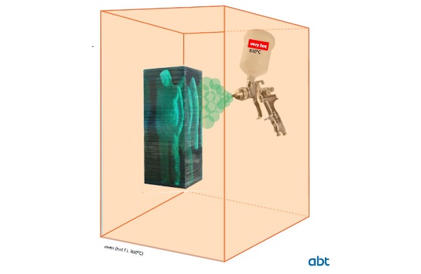
At the root of this project lies a simple idea to spray printed glass (SPG). Can three-dimensional glass structures be produced using an application process similar to an airbrush gun (see Figure 1)? For a production of three-dimensional glass structures, a mould is normally made into which the glass is casted, like applications in (Oikonomopoulou et al. 2020). The first response was that this approach was not feasible. The mechanical properties, especially of soda-lime silicate glass (SLG) with large dimensions, do not allow the glass to be exposed to significant temperature fluctuations outside a heated chamber during a production process with temperatures above the glass transformation temperature (SLG 530°C). The idea and the associated challenges were evaluated by practitioners (glass equipment maker) and the authors. Together they developed innovative solutions. Through a series of experiments, these solutions gradually enabled the additive deposition of glass in powder form without the need for a heated chamber.
This research is driven by the idea to further improve flat glass sheets beyond their flat applications in glass facades. The mechanical performance of glass panes can be influenced, and the deflection reduced by applying stiffeners. Another possibility would be to increase the edge strength by smooth coating with SPG. In addition, there is the creative freedom that the SPG process can offer the user, like artists.
2. Process of spray printing glass and materials
2.1. Powder flame spraying
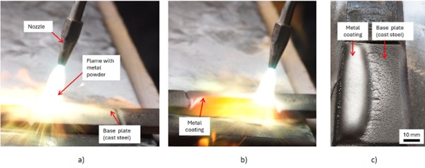
Flame spraying or powder flame spraying is a process in which material is applied to a surface to coat or repair it. There are various methods of flame spraying, but they generally involve heating coating material to high temperatures and applying it to the target surface. Typically, this is done in two steps: First, the coating material, often in powder form, is heated or melted to a high temperature. This can be done using a flame, an arc, a plasma discharge, or an arc plasma source. Once the material is heated, it is sprayed onto the target surface (second step). There, it cools down and forms a layer that adheres to the surface. Both steps can also run in parallel. The thermal spraying process can be used to apply a variety of materials, including metals, ceramics, polymers, and composite materials. It is commonly used in industry to protect surfaces, prevent corrosion, reduce abrasion, or repair components. Figure 2 shows a cast steel plate with an metal coating out of a powder flame spraying process. Details information about the general process are available in (Bloulos et al. 2021), (Dorfmann 2018).
2.2. Powder flame spraying with glass - Spray Printing Glass (SPG)
Figure 3 a) illustrate the structure of the used powder flame spraying device (oxy-acetylene thermal spray torch SuperJet-S (CastoSuperJetS 2024)) used for the investigations. In addition to this SuperJet-S torch, the high performance torch CastoDyn DS 8000 (CastoDS8000 2024) was used for a few tests.
Glass powder is heated by means of an acetylene-oxygen flame and sprayed onto a glass plate by flame pressure. According to the information of the torch manufacturer (company Castolin Eutectic), grain sizes in the range of 50 ... 200 μm are suitable for such a process. The acetylene goes freely from the pressure valve to the nozzle. The oxygen is after the pressure valve mixed with the powder material in the mixing chamber of the flame spraying device or torch. The powder supply is controlled via the feeding arm. The oxygen-powder (glass) mixture only meets the acetylene at the end of the nozzle and is ignited there. With the lock valve, the gas supply can be interrupted, and a flame jerk can be prevented. The torch used in this study is the Superjet-S. This is an oxy-fuel hand torch for hot powder flame spraying of metallic powders. Due to its size, it is intended for smaller applications and repairs. The torch is powered with an oxygen acetylene mixture in a ration approx. 1.2:1. Nozzles of different sizes are available for the burner. In this study, the following nozzles were used:
- A0 & A0HS: Nozzle with a diameter of 0.75 mm. Once as a normal version (stainless steel) and once as a hardened version made of tungsten carbide.
- A1 & A1HS: Nozzle with a diameter of approx. 1.0 mm. Once as a normal version and once as a hardened version made of tungsten carbide.
- A2HS: Nozzle with a diameter of 1.2 mm. Only as a hardened version (tungsten carbide).
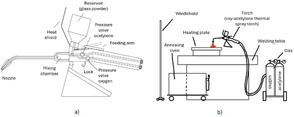
The general setup for the investigations is illustrated in Figure 3 b). The experimental set-up is kept very simple. A heating plate is placed on the welding table. A graphite plate or paper is placed between the glass plate and the heating plate. The glass plates are then placed on it (for preheating). The preheating temperature of the heating plate amounts approx. 300° up to 400°C. On this graphite underlay is also sprayed directly. Next to the welding table is an annealing oven. A wind shield is set up around the test setup.
2.3. Materials for spray printing glass (SPG)
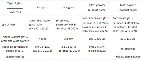
Glass plates out of soda-lime silicate glass or borosilicate glass were chosen as substrate plates. The glass thicknesses and plan dimensions were minimised to reduce the risk of thermal breakage. The samples are cut by hand with a glass cutting tool. An overview of the different materials is listed in Table 1.
Table 1: Overview of glass material
2.4. Sample Production
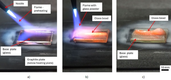
The produced samples for the tests were made manually (see Figure 4.) For the spray printed glass or powder flame spraying glass, the glass plates were preheated with the heating plate and with a smooth flame of the torch without glass powder as first step. The processing temperature amounts in the joining area approx. 700 ... 1000°C. Throughout conducting the experiments, we developed a feeling for the production process, so that fewer glass plates broke and larger glass plates could be applied. This trial-and-error method improved the quality of the SPG specimen significantly. For example, while heating a slight glow in the glass plate can be seen, indicating that the temperature of the glass plate is in the desired range. After heating the plates, the flame of the torch was focused on joining area of the plates for a longer period of time and glass spraying could begin.
Subsequently, glass powder is added to the flame and a glass bead is sprayed onto the glass substrate. We paid particular attention to the first layers in order to create a substance-to-substance bond between glass plate and the glass powder. After the first layer, we usually added more material and created spatial geometries. The procedures varied greatly, from only thin layers with subsequent reheating to the continuousapplication of the material. Also, the speed at which the torch was moved, the flame settings and distance from nozzle to object were varied during spraying. After the object was completed, it was heated uniformly with the torch. In order to avoid thermal induced glass breakage the samples were placed directly in the annealing oven after production. The process steps of SPG are shown in Figure 4.
The manufacturing procedure was much more complicated and obscure than the experimental setup indicates. Working with the glass and the torch depends on a large number of parameters (temperature fields, heat flow, material flow, grain sizes, distance torch and glass plate, viscosity behaviour, material properties,...). Many of these are difficult to influence or control in this experimental set-up. A scientific or systematic approach was difficult to implement, hence the trial-and-error approach. An experienced glassblower supervised the production of the samples.
3. Investigation
3.1. Feasibility of production and methods
In this section, the feasibility of the two types of glass, soda-lime silicate and borosilicate, is presented. Exemplary test samples are shown. Due to the handmade production and the objective to show the general feasibility of SPG, the emphasis in testing was on generating several different samples rather than several samples per test series. It should be mentioned that initial tests were also conducted using fused silica. These were not successful due to the fact that the required process temperatures for fused silica (working temperature between 1700 to 2100°C) on fused silica glass plates were not achieved.
The following methods were used for the investigations: (I) visual inspection without auxiliaryequipment; (II) visual inspection with auxiliary equipment (like scanning electron microscopy - SEM); (III) residual stress analysis visualized by photo-elastic tests with polarized light. These investigations were carried out to identify cracks, voids, interfaces and material inhomogeneity in the fused joints.
Some samples show a lot of yellow discolouration and black inclusions. It is assumed that the yellow discolouration is the result of metal abrasion (probably abrasion of the nozzle), which is included in the molten glass powder. The abrasion is recognisable by observing the nozzle outlets after the SPGprocess. During the production of all samples, it became apparent that the hardened nozzle (HS, tungsten carbide) is more suitable for the SPG process because of less abrasion. The black inclusions are probably the result of soot caused by incomplete oxidation process. The "correct" preheating of the glass plates and their thermal post-treatment in the annealing oven led to a significant reduction or avoidance of cracks within the project samples.
3.1.1. Soda-lime silicate glass
Initially, many cracks still occurred during the production process with soda-lime silicate glass (SLG). This could be improved by adjusting the thermal management. All samples presented here in this section with one exception, were produced with torch SuperJet-S, hardened nozzle A1HS (nozzle diameter 1 mm). The temperature of the heating plate was 300°C while spray printing glass and the oven temperature was set to 500°C for post process annealing.
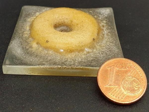
Figure 5 displays two samples each on a SLG-plate (50 x 50 x 4 mm³). The circular ring structure (see Figure 5a) and the circular cone segment (see Figure 5b, height 35 mm) could be produced. Both structures have many pores (distributed regularly) and the appearance is rather opaque and not glassy.The uniformly distributed pores indicate that the process was too fast, as the air inclusions could not evaporate.
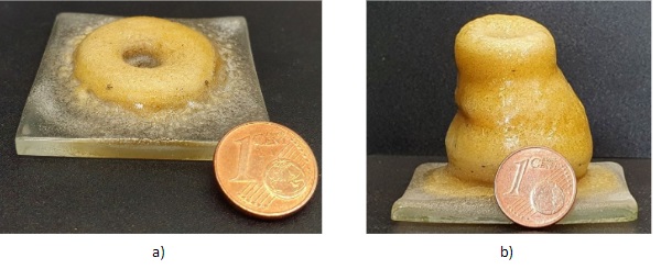
Figure 6 shows a 3D-line structure (length 50mm, height 25 mm) on a 4 mm thick SLG plate (plan dimensions 50 x 50 mm²) with pores (max. diameter 300 μm) in the interface region between base plate and added glass beads, with yellow discolouration and without cracks.
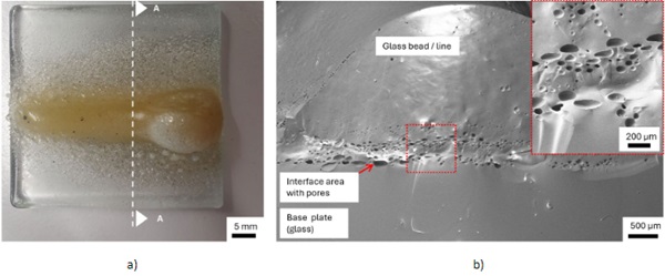
The pores can be caused if the glass is processed too high in temperature. The exemplary sample V6.1 in Figure 6 was manufactured with the following parameters: 20 mm blue flame cone; distance substrate torch approx. 30 mm. These parameters initially seemed suitable. The line structure appears in large areas glassy and translucent, apart from the yellow colours. No interface boundary line can be recognised between the base plate and the added material, as well as between the individual layers of the added material. This demonstrates the good material homogeneity of the bond with the exception of the bubble formation in the interface area.
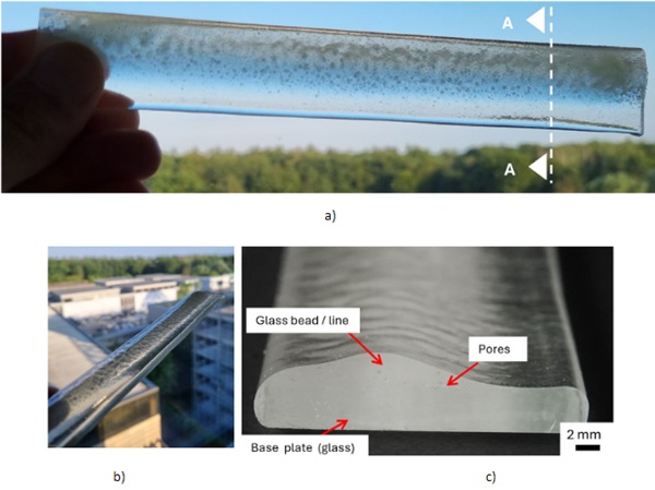
For the next iteration step a high-performance flame spraying torch CastoDyn DS 8000 (CastoDS8000 2024) was applied to avoid undesirable pores and yellow discolorations. The SLG beads were sprayed directly onto a 190 mm long glass plate (width 30 mm, 4 mm thick, SLG). Apart from the ends of the sample, an additional layer thickness of approx. 2.6 mm was achieved. The blue flame cone measures 50 mm and the distance between substrate and nozzle approx. 100 mm. The applied structure is glassy and has very few pores and no discolorations (see Figure 7). As a result, the sample appears translucent and quasi transparent. No residual stresses were detected by photo-elastic tests with polarized light. This example clearly demonstrates the general feasibility and potential of this technology.
3.1.2. Borosilicate glass
Borosilicate glass is due to its lower CTE value of 3.3 E-6 [1/K] and higher thermal shock resistance more reliable to use in such a process. The working point of borosilicate (1270°C) glass is still low enough to be achievable using the torch. The demonstrated samples within this section were produced with torch SuperJet-S, hardened nozzle A0HS (nozzle diameter 0.75 mm) and A1HS (nozzle diameter 1 mm). The temperature of the heating plate is set to 300°C. A subsequent oven process was carried out for all samples except sample V4.4.
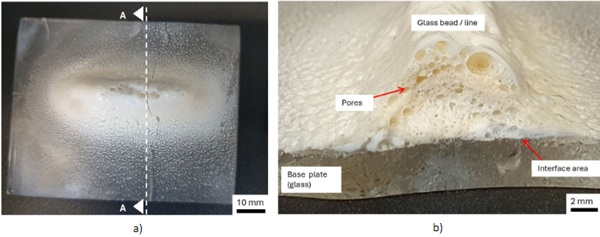
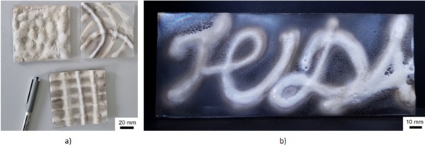
Figure 8 displays a 3D-line structure (length 50mm, height 25 mm) on a 4 mm thick SLG plate (plan dimensions 80 x 65 mm²) with large pores in the added glass structures. The reasons for the pores here are the use of hollow glass beads (solid material was not available) and the rapid deposition of the material prevent the complete air escape. Figure 8 a) shows that the pores appear everywhere and also in different sizes. It is noticeable that the pore volume increases over the thickness direction(reference base plate). The visible crack occurred during the cooling process, which did not take place in the oven.
The process is suitable for applying rib-like structures to the entire glass plate or writings (see Figure 9). The non-uniform temperature profile across the entire thickness resulted in permanent warping of the created glass structures.
4. Conclusion and Outlook
The presented investigations demonstrated the general feasibility of spray printing glass technology.The experimental outcomes indicate that the produced samples exhibit low transparency with high energy input. In its current form, the process appears feasible mainly for artistic purposes. One advantage is the ability to incorporate a wide range of colors using colored glass powder, and the artist can achieve complete shape freedom during the application process using a powder flame spraying device. Beyond the artistic aspect, two additional points warrant attention for future investigations: the SPG process can achieve very high deposition rates, which may distinguish it from other glass 3D printing processes. Moreover, the experiments revealed a redundancy: introduced cracks in the test specimens were halted by the pores, preventing further crack propagation. This redundancy could open new possibilities for structural safety in glass applications.
The realisation of the brainwave spray printing glass into a general process (still manual) was only possible through close cooperation between practitioners, researchers and students. Following the motto "Impossible is not an option", this diverse team broke through self-imposed scientific boundaries and made significant progress in a short time, achieving what was previously considered impossible.
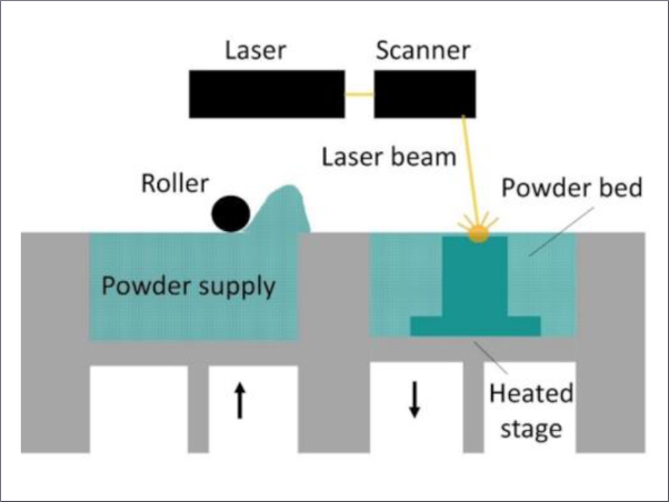
For the spray printed glass process to be utilized in building industry or other fields with high glass quality requirements, it is crucial to gain better control over the process parameters. As the test sample shown in Figure 7 illustrates, choosing the correct process parameters can result in the additive manufacturing of transparent glass structures using this method. This requires a machine implementation, including a heated building chamber to precisely control deposition rate, temperature fields, heat flow, distance torch to glass plate, etc. In terms of sustainability, replacing the currently used acetylene with hydrogen is advisable. Besides reducing the carbon footprint, a hydrogen flame offers additional benefits. Additionally, to reduce energy consumption, laser-assisted heating of the powder material, similar to that used in metal 3D printing or glass 3D printing (Fateri & Gebhardt2015) could be considered. Such an implementation is complex but promises the best results due to the high level of process control.
Acknowledgements
The authors would like to thank the Oosterhoff group, especially the think tank Quake and ABT, who made it possible to carry out this research work by a funding. Special thanks go to the glass equipment maker Maria Voss of the TU Darmstadt glass-blowing workshop.
References
Borofloat33: Schott Borofloat®33. Datasheet. Schott Glas. https://www.schott.com/de-de/products/borofloat-P1000314/downloads, Accessed: 20.4. 2024, 2024.
Bloulos, M. I., Fauchais P.L., Herberlein J.V.R.: Thermal Spray Fundamentals – Form Powder to Part. Springer Cham. https://doi.org/10.1007/978-3- 030-70672-2, 2021.
Fateri, M., Gebhardt, A.: Selective Laser Melting of Soda-Lime Glass Powder. Int. J. Appl. Ceram. Technol., 12: 53-61. https://doi.org/10.1111/ijac.12338, 2015.
Dorfmann, M. R.: Handbook of Environmental Degradation of Materials (Third Edition) – chapter 22 Thermal Spray. William Andrew Publishing, https://doi.org/10.1016/B978-0- 323-52472-8.00023-X, 2018.
CastoDS8000: CastoDyn DS 8000 Kits; https://www.castolin.com/product/castodyn-ds-8000-kits, 2024.
CastoSuperJetS: SuperJet-S- Kits; https://www.castolin.com/product/superjet-s-kits, 2024.
EN 572-1: Glass in building—Basic soda-lime silicate glass products—Part 1: Definitions and general physical and mechanical properties: Bd. 13.220.40; 13.220.50. Beuth Verlag GmbH, 2016.
Oikonomopoulou, F., Bhatia, I. S., Damen, D., Van Der Weijst, F., Bristogianni, T.: Rethinking the Cast Glass Mould. Challenging Glass Conference Proceedings. Challenging Glass 7, Challenging Glass Conference Proceedings, Vol. 7, https://doi.org/10.7480/cgc.7, 2020.
SiLiAir: SiLibeads AIR® Hollow Glass Beads, https://www.sili.eu/en/products/glass-beads/hollow-glass-beads-silibeads-air, Datasheet, 2022.
SiLiSolid: SiLibeads SOLID Micro Glass Beads, https://www.sili.eu/en/products/glass-beads/micro-glass-beads-silibeads-solid, Datasheet, 2022.