Source: Glass Structures & Engineering
Authors: Kyriaki Corinna Datsiou & Ian Ashcroft
DOI: https://doi.org/10.1007/s40940-024-00257-0
Abstract
Additive manufacturing of glass using laser powder bed fusion has been recently developed, demonstrating its potential to be applied in small scale applications such as flow reactors for the chemical engineering and pharmaceutical manufacturing industries. While previous research demonstrated that complex 3-dimensional shapes can be manufactured, built parts are often brittle, exhibit high porosity and lack transparency. This study employs a transient, heat transfer finite element analysis to shed light on the thermal response of laser—glass powder bed interaction and the impact of processing parameters. Through this understanding, the research seeks to identify practical strategies that can be employed to improve the quality and properties of the built parts.
Bulk solid and powder soda lime silica glass properties are used as input in the model, while the laser heat flux and scan strategy, conversion of powder feedstock to bulk solid glass and heat losses from convection and radiation effects are introduced in the model through Fortran coding. The study showed that effective powder consolidation, resulting in well-defined geometrical features, is achieved for temperatures near the glass melting point. Additionally, uniform consolidation depths and widths can be achieved by increasing laser power, elevating substrate temperature and reducing scan speed within certain limits, whilst ensuring hatch spacing is below the corresponding single scan track width for unidirectional adjacent laser trajectories.
1 Introduction
Additive manufacturing, has emerged as a pivotal technology in recent decades, facilitating the manufacture of complex geometries with minimal waste. It offers substantial benefit in customising components to meet specific requirements while being cost-effective for prototyping or where a limited number of components is required. The above apply to metals, ceramics and polymers and could also extend to glass. While it is acknowledged that additive manufacturing of glass cannot currently outperform the efficiency of traditional manufacturing methods, such as the well-established float process for flat glass or moulding and extrusion processes for mass production components, it offers significant advantage for developing complex geometries that are challenging or impractical to achieve through conventional means.
Additive manufacturing for glass to date spans across direct and indirect methods (Xin et al. 2023). Direct methods involve high temperatures to sinter/melt glass feedstock in a single step process such as laser powder bed fusion (Datsiou et al. 2019, 2021; Fateri & Gebhardt 2015), extrusion (Inamura et al. 2018; Klein 2015) and directed energy deposition (Grabe et al. 2021; Spirrett et al. 2023). In contrast, indirect methods are performed at ambient conditions using a composite material, i.e. a binder that encapsulates the glass feedstock, to print a “green” part. This is followed by post-processing, that may include drying, binder burning and sintering steps. Stereolithography (Kotz et al. 2017; Liu et al. 2018) and direct ink writing (Nguyen et al. 2017) are notable for glass among indirect methods. Although indirect methods are recognised for their ability to produce optically transparent parts, these often lack in dimensional accuracy due to anisotropic shrinkage associated with post processing. Laser powder bed fusion has the potential to address this limitation as a single step process. Moreover, it presents the additional advantage of preventing “layered” features and anisotropic properties, that are commonly associated with nozzle-based processes such as extrusion.
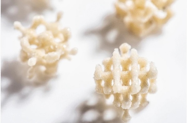
To date, process maps for laser powder bed fusion (LPBF) of soda lime silica glass have been populated to identify its processing window (Datsiou et al. 2019, 2021). These studies also demonstrated the ability to manufacture complex 3-dimensional shapes, such as the lattice structures illustrated in Fig. 1. However, glass remains a challenging material to process with LPBF. Its low absorptivity for wavelengths used in most LPBF systems (typically operating around 1100 nm) impedes laser processing. Coupled with the high melting temperature of glass, this leads to high energy density requirements for achieving feedstock consolidation. Consequently, the LPBF process generates high temperature gradients within the built parts leading to the development of thermal stress and cracking, which affects the flexural strength (Datsiou et al. 2021) and thereby limits the application of this technology.
Finite Element Analysis (FEA) has emerged as a fundamental tool for better understanding the thermal behaviour of the LPBF process in metals. Despite numerical challenges in realistic modelling of the laser source, providing accurate material properties and realistic accounting for heat losses, experimental thermal investigation is difficult to undertake due to localised ultra-fast heating—cooling and melting—solidification phenomena. Early studies employed numerical models to simulate the thermal behaviour and predict temperature distributions and melt pool characteristics during LPBF (Gusarov & Smurov 2010; Kolossov et al. 2004; Roberts et al. 2009). More recently FEA was used for optimisation, providing the correlation between thermal response and laser processing parameters (Li et al. 2020; Li & Gu 2014; Zhang et al. 2018) while thermomechanical analyses were also used to predict residual stress development and optimise scan strategies (Parry et al. 2016; Wu et al. 2017).
Despite the available research on the numerical optimisation of LPBF for metals, there is a lack of research on glass. This study develops a transient, heat transfer finite element analysis model of a moving heat source operating in a glass powder bed in order to capture the thermal behaviour and investigate consolidation characteristics. The model is validated against experimental results and is subsequently extended to capture the impact of set-up and processing parameters, including substrate material and preheating temperature, laser power, scan speed and hatch spacing. The primary goal of this study is to gain a comprehensive understanding of the thermal response of LPBF of glass and identify practical strategies that can be employed to improve the quality of built parts. Section 2 below provides an overview of the method, including a detailed description of the FEA model and the material properties of glass. Section 3 presents and discusses the obtained results, including the validation of the numerical model against experimental results, whilst Section 4 summarises important results and conclusions.
2 Method
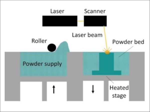
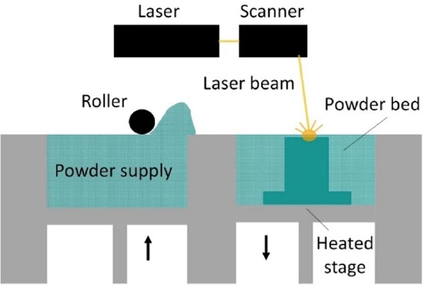
LPBF is an iterative additive manufacturing process extensively used for metals. In LPBF, a high-power laser is used to selectively sinter or melt powder particles in layers of controlled thickness to create a three-dimensional object (Fig. 2). In detail, a thin layer of powder is spread on the build platform for processing, which incorporates a heated stage to reduce temperature gradients and hence, residual stress in built parts. The layer is subsequently processed by the laser source which moves in predetermined trajectories based on the selected scan strategy and the cross section of the geometrical model. After each layer is processed, the stage moves downwards, and a fresh layer of powder is deposited. The sequence is repeated until the built part is complete.
In this study a thermal FEA model is developed to simulate the LPBF process and predict the heat distribution within the powder bed. Heat conduction in solids takes the following form:

where Q is the volumetric heat flux, ρ is the density of the material, Cp is the specific heat capacity, λ is the thermal conductivity and T is the temperature.
This can be expressed in 3d coordinate space as follows:

In addition to conduction, heat losses qtot (Eq. 4), arising from convection qcon, and radiation qrad, effects (Eq. 3a-b) also occur and must be considered in the analysis.
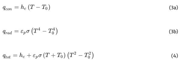
where hc is the heat transfer coefficient, εp is the emissivity of the powder bed, σ = 5.67·10–8 W/m2K4 is the Stefan Boltzmann constant and T0 is the temperature of the environment.
2.1 Finite element analysis model
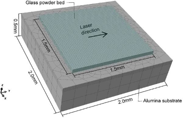
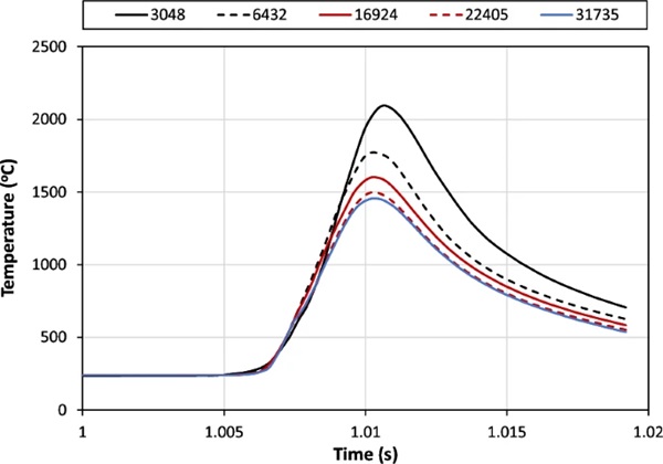
The FEA model was developed in Abaqus 2023 (Dassault Systemes, USA) to simulate the laser powder bed fusion process through a transient heat transfer analysis. The model closely matches the set-up used in the experimental studies of Datsiou et al., (2019, 2021). In detail, the model (Fig. 3) features a 1.5 × 1.5 × 0.07 mm3 glass powder bed on a 2.0 × 2.0 × 0.5mm3 dense substrate. Alumina substrates were considered in this study unless otherwise specified. The model was discretised with 8-node, full integration heat transfer brick elements, DC3D8, (Abaqus 2023 Documentation 2023). A fine mesh with an element size of 30 μm was used for the powder bed with a total of 22,405 elements, while a coarser mesh was used for the alumina substrate to reduce the computational cost. A mesh convergence study with varying density for the mesh (Fig. 4) was initially undertaken for a single linear scan track (laser power P = 75 W and scan speed v = 26 mm/s) confirming the suitability of the selected mesh (22,405 elements) and providing balance between output accuracy and computational cost.
Individual analysis steps were introduced in the FEA model to describe each step of the LPBF process for a single layer i.e. pre-heating of the substrate and laser processing of the powder bed.
Preheating of the substrate: A step with a time period of 1 s was introduced at the beginning of the analysis. This time period was found to be sufficient for the substrate to be effectively pre-heated. A fixed temperature of 250 °C (unless otherwise specified) was applied to the lower and side surfaces of the substrate. This was to replicate the experimental conditions in which these surfaces are in direct contact with the heat source. The pre-heating temperature was preserved during the process while an ambient temperature of 20 °C was used.
Laser processing of the powder bed: A laser processing step was introduced after the preheating step. Its time period was adjusted to account for the selected laser scan speed and the scan strategy / distance to be covered. Laser processing of the powder bed was incorporated through a moving heat flux, described by a Gaussian distribution (Papazoglou et al. 2022) which takes the following form:

where η is the absorption coefficient for the powder, P is the laser power, R0 is the laser spot size and r is the radial distance from the centre of the laser beam to the point of interest on the powder bed.
The heat flux input was defined in a DFLUX user-subroutine through a Fortran script. The scan strategy (laser trajectories) and the laser processing parameters including laser power, scan speed and spot size were also included in the script.
Powder consolidation was integrated in the FEA model through a solution dependent state variable (SDV). During the analysis the state variable changed as a function of temperature based on the output results. A state variable value of:
- SDV = 0 was used to describe glass powder elements. This was the opening value assigned to all elements of each new powder layer by default. Powder elements that did not consolidate during laser processing maintained SDV = 0.
- SDV = 1 described bulk solid glass elements that consolidated during the process. The SDV changed from 0 to 1 when the element temperature exceeded the transition temperature of glass (Tg = 575 °C). For T ≥ Tg, powder particles soften and fuse together beyond the transition temperature, leading to powder consolidation, without necessarily reaching the melting temperature of glass (Tm = 1280 °C), (Kamyabi et al. 2017).
The phase change from powder to solid was implemented in Abaqus with a USDFLD user-subroutine, coded in Fortran. The solution dependent state variable was updated in every analysis increment and determined the material properties (glass powder or bulk solid glass) to be used per element.
Heat losses from convection and radiation effects were combined as shown in Eq. 4 and considered in all steps of the analysis through a FILM user subroutine, that was also coded in Fortran. A summary of relevant input parameters used for the FEA model are available in Table 1.
Table 1 Summary of FEA input parameters - Full size table
Overall, a total of 23 FEA models of the LPBF process of a single layer were undertaken in this study to understand the thermal behaviour and the consolidation characteristics for soda lime silica glass. The investigation involved a parametric study of the effects of laser power, scan speed, hatch spacing and substrate temperature and material to explore their impact on the additive manufacturing process.
2.2 Materials
The powder feedstock material used in this study was soda lime silica glass (72.1% SiO2—13.7% Na2O—10.2% CaO—2.5% MgO—1.1% Al2O3) with an average particle size of 44 μm, to match the feedstock material used in Datsiou et al., (2021). The material properties for the FEA model were defined for both glass powder (SDV = 0) and bulk solid (SDV = 1) states. The thermal conductivity, λs, and specific heat capacity, Cp,s, for bulk solid glass are temperature dependent and respectively described by Eqs. 6 and 7 (Carré & Daudeville 1999):

where T is the material temperature in °C.
The Sih & Barlow (1992) model was subsequently employed to predict the effective thermal conductivity of the powder bed, which is simplified to the following form based on Dai & Shaw, (2004):

where φ is the fractional porosity of the powder bed, λf is the thermal conductivity of the fluid surrounding the powder particles (argon gas in this study) and λr is the thermal conductivity of the powder layer due to radiation, described by Eq. 9:
![]()
where xr is the average powder particle size and F = 1/3 is the view factor.
Additionally, the rule of mixtures (Alexopoulou et al. 2022) in Eq. 10 was used to predict the specific heat capacity, Cp,p and the density of the powder bed, ρp.

where Cp,f and ρf are the specific heat capacity and the density of argon gas respectively.
To include radiation effects, the emissivity of the powder bed, εp, is required. This was predicted from the emissivity of the bulk solid phase, εs (Sih & Barlow 2004) and is expressed as follows:
![]()
where εH is the emissivity of cavities and AH is the area fraction of the surface covered by radiating cavities, which takes the following form:
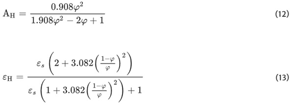
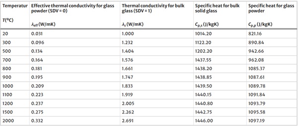
Based on the above, the thermal properties used in the FEA for bulk solid and powder soda lime silica glass are summarised in Table 2 as a function of temperature while other relevant material properties are available in Table 3. These include the glass melting and transition temperature as well as the laser absorption coefficient which depend on the selected glass feedstock composition.
Table 2 Thermal properties for soda lime silica glass in bulk solid and powder state - Full size table
Table 3 Relevant material properties used in the FEA model - Full size table
3 Results and discussion
3.1 FEA validation
Firstly, the FEA results were experimentally validated. While temperature output was not directly available, the width of the scan track was utilized to assess the accuracy of the FEA model. The experimental investigation involved a commercial benchtop LPBF system (ReaLizer GmbH SLM-50, Germany) to process the feedstock material, SLSG44 (Datsiou et al. 2021). The selected material provides a good match to the properties used in the FEA model of this study, although some discrepancies may be present in thermal conductivity and specific heat capacity that were derived from analytical approaches (Sect. 2.2). The feedstock material was deposited in a single layer of uniform thickness on a heated alumina substrate. A single linear scan track was undertaken with the following parameters: laser power of 75 W, scan speed of 26 mm/s, layer thickness of 0.07 mm, scan track length of 7 mm, laser focus position 9.55 mm (which corresponds to a spot size of 60 μm) and substrate temperature of 250 °C. The width of the consolidated glass powder was subsequently quantified with optical microscopy (Fig. 5a). Ten readings were obtained at equal intervals (away from the two ends) indicating an average width of 198 μm.
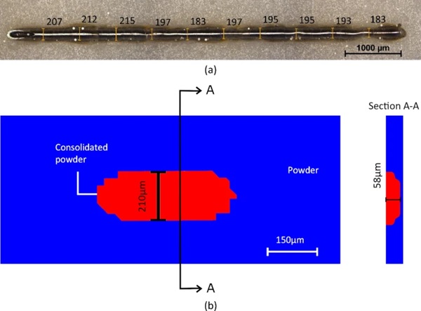
A FEA model replicating the parameters of the experimental test was developed. The only difference was selecting a scan track length of 0.5 mm, to minimise computational cost. The solution-dependent state variable (SDV), integrated into the USDFLF user subroutine, was used to determine the scan track width. The model predicted a width of consolidated glass (SDV = 1) of 210 μm, ignoring the end regions of the track (Fig. 5b). This shows good agreement with experimental results with a difference of 6%.
3.2 Thermal behaviour and powder consolidation
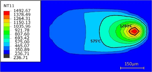
Figure 6 illustrates the top view of a typical temperature contour for a single layer scan track, obtained using a laser power of P = 75 W and a scan speed of v = 26 mm/s at a time of t = 0.01832 s. It is evident that the temperature exceeds the transition temperature of glass (Tg = 575 °C) and therefore powder consolidation was achieved. The consolidation region is marked with a thick black line that matches the 575 °C isotherm while the significantly smaller melt pool region, exceeding 1280 °C, is also marked. The contour isotherms on the forward part of the consolidation region are notably condensed compared to the rear part. This is attributed to the lower thermal conductivity of the powder that surrounds the forward part of the consolidation region compared to the already consolidated material at the rear, which dissipates heat at a faster rate. Moreover, it is worth noting that the 3D geometry of the consolidation region evolved with time and increased in size (Fig. 7). At the onset of laser processing, an almost hemispherical shape (e.g. t = 0.0005 s) was apparent, however, this soon transitioned into a “comet tail” geometry, a shape that agrees with common observations of melt pool during LPBF of metals, for instance in Fu & Guo, (2014).

The consolidated powder exhibited a depth of 58 μm while the width measured 210 μm (Fig. 5b) indicating a significant difference of 72%. This observation is in line with findings in B. Li et al., (2023) for Inconel 625 where the consolidated width exceeded the consolidated depth. However, in this case it also indicates that the laser failed to effectively consolidate the entire powder layer thickness (tl = 70 μm), which is essential in LPBF. However, “necking” of powder particles (i.e. gradual softening of powder particles and merging with one another and the substrate) was expected to occur and some degree of adhesion to the substrate to be achieved.
3.3 Impact of set-up and processing parameters on scan tracks
This section discusses the impact of set-up and processing parameters, including the choice of substrate and substrate temperature Tsub, laser power P, scan speed v, energy density ED (Eq. 14) and hatch spacing h.

Substrate temperature As discussed previously, powder consolidation was not achieved through the entire layer depth for an energy density of ED = 41.21 J/mm2 (P = 75 W, v = 26 mm/, tl = 0.07 mm), and a substrate temperature of Tsub = 250 °C (Fig. 5b). The same outcome was observed for scan tracks with higher energy density, confirmed up to a value of ED ≤ 108 J/mm2. This can be attributed to the significantly higher thermal conductivity of the alumina substrate (λa = 15.1 W/mK) compared to glass (λs = 1.19 W/mK and λeff = 0.096 W/mK for bulk solid and powder states respectively) at 250 °C. A high rate of heat dissipation by conduction therefore occurred at the interface of the glass powder with the substrate. This prevented the development of temperatures exceeding the transition temperature of glass which is essential for powder consolidation.
However, it was found that by raising the substrate temperature to Tsub = 500 °C, i.e. just below the transition temperature of glass, the entire powder layer can be consolidated (Fig. 8a). This led to a 21% increase in consolidation depth compared to a substrate temperature of Tsub = 250 °C, while a 57% increase was noted for the consolidation width. Raising the substrate temperature did not affect the maximum temperature developed at the top surface of the glass powder bed during laser irradiation. It is also worth noting that powder consolidation at the lower surface did not occur simultaneously with the top surface, but lagged behind the passage of the laser source by a few ms (Fig. 8b).
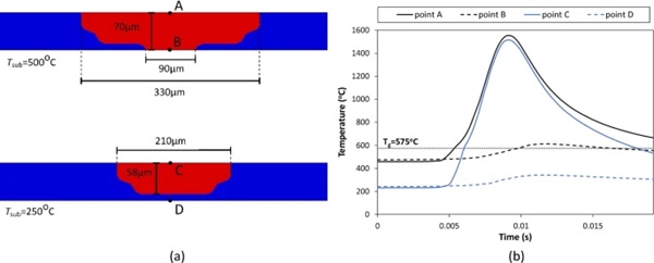
Overall, raising the substrate temperature presents a twofold advantage, as not only does it increase the consolidation depth to 70 μm, but it also reduces temperature gradients in the zone of laser treatment within the built parts during LPBF. The latter is expected to limit the development of residual stresses and consequently cracking in the built parts, as shown for zirconia ceramics in Q. Liu et al., (2015). Experimental evidence also suggested that raising the substrate temperature to 500 °C softens the glass powder particles before laser irradiation, limiting the required energy density and resulting in fully molten, transparent / “glassy” components (Spirrett 2021).
Substrate material Substrates in LPBF are typically chosen to match the powder feedstock to ensure thermal compatibility and good adhesion. In this study, alumina substrates were selected due to their superior thermal shock resistance, as soda lime silica glass substrates were previously found to crack (Datsiou et al. 2021). However, a substrate simultaneously ensuring thermal shock resistance and compatible thermal properties (thermal conductivity and coefficient of thermal expansion) to soda lime silica glass, could be beneficial in improving the consolidation depth.
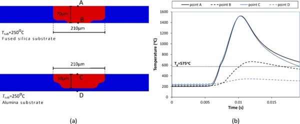
Fused silica substrates with a thermal conductivity of λfs = 1.53 W/mK at 250 °C were identified as a potential candidate in this study. Indeed, results for single scan tracks (P = 75 W and v = 26 mm/s) show that consolidation was successfully achieved through the entire powder layer at a substrate temperature of 250 °C (Fig. 9a). It was found that the choice of substrate did not affect the surface temperature development but only reduced the heat transfer by conduction at the interface with the substrate leading to the development of temperatures exceeding the transition temperature of glass (Fig. 9b). However, experimental validation is required to verify that fused silica substrates provide good adhesion with the feedstock material and that they will not exhibit cracking during the process.
Laser power The impact of laser power for a range of 20 W ≤ P ≤ 120 W and a scan speed of 30 mm/s was investigated for scan tracks on alumina substrates with a temperature of Tsub = 250 °C to replicate the experimental set-up used in Datsiou et al., (2021).
As expected, the maximum temperature at the top glass surface increased with increasing laser power, with a linear trend (Fig. 10a). The transition temperature of glass (Tg = 575 °C) was exceeded in all scenarios while the melting temperature (Tm = 1280 °C) was exceeded for laser powers greater than 60 W. Previous experimental observations indicated that effective consolidation, resulting in well-defined walls of uniform width, was reliably achieved for laser powers exceeding 55 W at a scan speed of 30 mm/s (Datsiou et al. 2021). This reveals that high temperatures equal to or greater than the melting temperature are essential for achieving effective consolidation. While powder consolidation can occur at lower temperatures, it comes at the cost of compromising the quality of the produced parts.
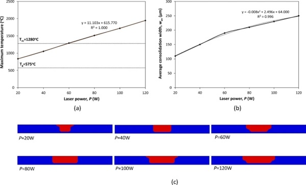
The consolidation width was found to increase with laser power (Fig. 10b). Uniform widths were only noted through the thickness for laser powers of 40 W and 80 W. The remaining scenarios exhibited a wider top that progressively narrowed with increasing depth (Fig. 10c), which can compromise dimensional accuracy. It is also worth noting that the maximum consolidation depth remained constant regardless of the laser power employed, which can be attributed to high conductive heat transfer at the interface with the alumina substrate.
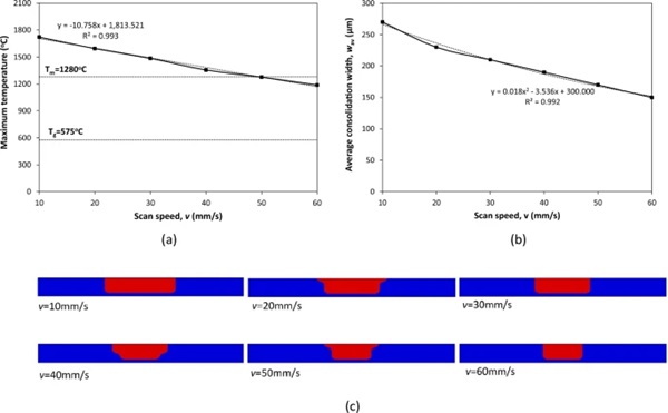
Scan speed Scan tracks with a scan speed ranging between 10 ≤ v ≤ 60 mm/s at a laser power of P = 75 W are investigated in this section on an alumina substrate with Tsub = 250 °C.
The scan speed was found to be inversely proportional to the maximum temperature at the top surface of the powder bed (Fig. 11a). The maximum temperature exceeded the transition temperature of glass in all scenarios, while the melting temperature was surpassed for scan speeds equal to or lower than 50 mm/s. This is in line with experimental observations that scan speeds exceeding 44 mm/s resulted in poor or no powder consolidation (Datsiou et al. 2021), highlighting again the significance of achieving high temperatures, close to the melting temperature of glass during thermal processing of glass powders. The average consolidation width reduced with increasing scan speed (Fig. 11b). Uniform through-the-thickness widths were noted for scan speeds of 10, 30 and 60 mm/s while the remaining scenarios exhibited a wider top surface (Fig. 11c).
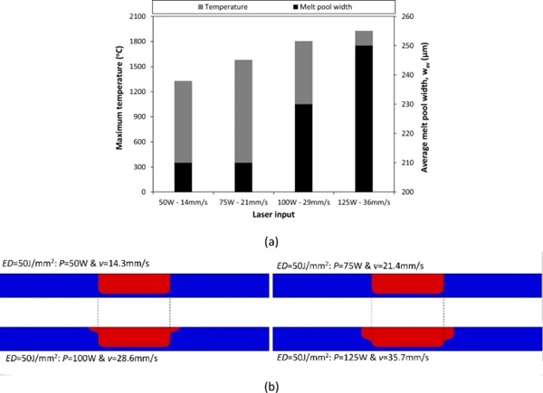
Energy density Four FEA models of scan tracks were undertaken on an alumina substrate with Tsub = 250 °C featuring energy densities of ED = 50 J/mm2 with the following parameter combinations: Scan track A: P = 50 W and v = 14.3 mm/s, Scan track B: P = 75 W and v = 21.4 mm/s, Scan track C: P = 100 W and v = 28.6 mm/s and Scan track D: P = 125 W and v = 35.7 mm/s.
It was found that the maximum surface temperature exceeded both transition and melting temperature of glass resulting in powder consolidation for all scan tracks (Fig. 12a). However, despite maintaining a constant energy density, the achieved consolidation geometry was not consistent (Fig. 12b). Scan tracks A and B exhibited uniform consolidation widths of 210 μm whilst scan tracks C and D displayed a wider top of 270 μm, although they also shared the 210 μm width in the lower part of the consolidated layer (Fig. 12b). It was found that the simultaneous increase of laser power and scan speed resulted in a rise in maximum temperature (Fig. 12a). These temperatures expanded the heat affected zone at the surface of the powder bed for scan tracks C and D leading to a wider consolidation top, but without any significant difference in depth.
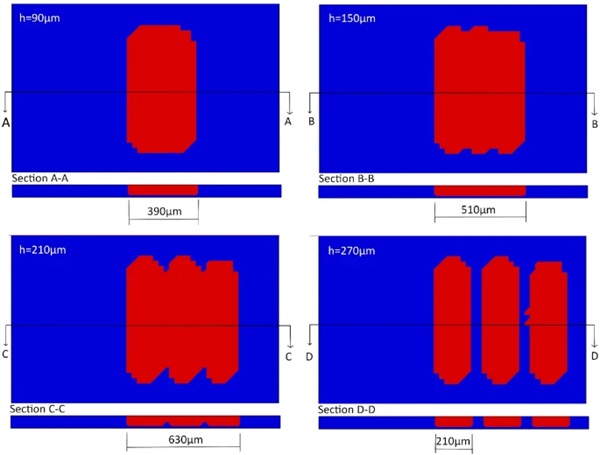
Hatch spacing Three consecutive unidirectional linear scan tracks, placed next to one another, were modelled in this section to identify the impact of hatch spacing between adjacent laser trajectories. A FEA model with laser power of P = 80 W, scan speed of v = 30 mm/, layer thickness of tl = 0.07 mm and substrate temperature of Tsub = 250 °C was employed for hatch spacings of 90 μm (HS90), 150 μm (HS150), 210 μm (HS210) and 270 μm (HS270).
The consolidation width for a single scan track under the specified processing parameters was wc,st = 210 μm (Fig. 10b). As expected, hatch spacings exceeding wc,st did not yield continuous consolidation, instead resulted in distinct scan tracks (Fig. 13). Continuous consolidation on the top surface of the powder bed could be achieved for hatch spacings equal to or lower than h ≤ wc,st while the total consolidation width for all 3 unidirectional scan tracks increased with increasing hatch spacing (from 390 to 630 μm for hatch spacings of 90 to 210 μm respectively). A hatch spacing equal to wc,st, however, failed to create a uniform consolidation depth which was instead apparent for h < wc,st (90 and 150 μm in this case). The above suggest that hatch spacings smaller than the individual scan track width are preferrable. This will ensure a uniform consolidation depth and prevent the encapsulation of pockets of unfused powder particles within the built parts that compromise their quality.
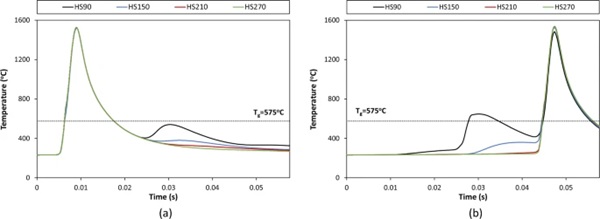
Irrespective of the selected hatch spacing, the maximum temperature in all scan tracks was found to be very similar (Fig. 14). However, for hatch spacing of 90 μm, it was noted that softening / fusing of powder particles could occur twice for adjacent scan tracks as the temperature at the midpoint of the second scan track exceeded the glass transition temperature both during the first scan track and during the second scan track i.e. when the laser source passes from that point. This was a direct result of the denser hatch spacing. Although reprocessing of powder particles could improve built part quality, care should be taken to avoid excessive energy density input that could result in spherical features and deviation from flatness at the top surface (Datsiou et al. 2021), typically referred to as “balling”, which warrants further investigation.
4 Conclusions
This study developed a transient heat transfer finite element analysis model to shed light on the laser powder bed fusion process for soda lime silica glass. The thermal response of the process was captured while the impact of laser processing and substrate parameters were investigated. Temperature dependent thermo-physical material properties were used as input for both glass powder and bulk solid states. Fortran coding in user subroutines was undertaken to simulate the moving laser heat source, conversion from powder feedstock to bulk solid glass and convection and radiation effects. The model was validated against available experimental data on single scan tracks. Salient conclusions drawn from this work are summarised as follows:
- The evolution of the glass consolidation region exhibited an initial hemispherical shape at the beginning of laser irradiation, quickly transitioning into a distinctive “comet tail” geometry, mirroring similar phenomena observed in laser powder bed fusion of metals.
- Alumina substrates at usual preheating temperatures (~ 250 °C) prevented powder consolidation through the entire powder layer. High heat dissipation by conduction occurs at the interface of the powder feedstock with the substrate, due to the significantly higher thermal conductivity of alumina compared to glass. Two distinct mitigations strategies have been identified in this study to improve consolidation depth namely, to increase the substrate preheating temperature to 500 °C (just below the transition temperature of glass) or to replace alumina with a thermal shock resistant material that is also thermally compatible with glass such as fused silica.
- Increasing laser power was observed to lead to increased maximum surface temperature and consolidation width whereas the inverse effect was noted for increasing scan speeds. Interestingly, surface temperatures and consolidation geometries were found to vary among scan tracks of equal energy density but different laser power and scan speed. This highlights the need for further investigation to understand the underlying factors contributing to this phenomenon.
- Although some degree of powder consolidation can be achieved for temperatures exceeding the transition temperature of glass, the combination of numerical results of this study with previous experimental observations revealed that effective powder consolidation, resulting in well-defined features, can be achieved when operating at temperatures within the proximity of the glass melting point.
- Uniform consolidation width and depth in a unidirectional scan strategy were effectively achieved when the hatch spacing was set below the corresponding single scan track width. This configuration ensured continuous and seamless consolidation across the laser processed layer.
These findings offer useful insights for the laser powder bed fusion of glass and should be considered for future practical applications. However, to comprehensively address the limitations of LPBF, further numerical investigation is necessary. A coupled thermomechanical analysis is recommended to understand the development of residual stresses and to capture temperature dependent volumetric changes in the glass. This will provide the foundation for developing mitigation strategies aimed at minimizing residual stresses and associated cracking, which will ultimately contribute to the improvement of strength and the overall quality of the built glass parts.

