First presented at GPD 2019
Used in long sections and small widths, the TSSA was able to effectively bend and hold shape after processing in an autoclave. The original purpose of the study was to evaluate at what length would the TSSA connection would fail in shear due to a mismatch in coefficient of thermal expansion for the glass and metal. However, the lengths studied indicated a potential to control the amount of bending due to length. The technique presents a potential art to create curved facades in lieu of the use of conventional structural silicone sealants under constant loads. As the TSSA is now the material under constant load, the curved glass could be installed in different façade assemblies via fittings.
Introduction:
Transparent Structural Silicone Adhesive (TSSA) is a unique crystal-clear film adhesive that is used to bond point supports of metal, typically stainless steel to glass. The TSSA is cured in an autoclave where glass is laminated usually with Polyvinyl butyral (PVB) or ionomer interlayers. Once the TSSA is cured onto the glass inside the autoclave, the fabrication and erection of the panels involves the simple attachment of engineered hardware on a project site. The TSSA application is a higher performance option than drilled mechanical attachments in glass which include the following advantages:
1. Use of Tempered glass is not mandatory, rendering a smoother façade appearance
2. TSSA attachment points can be designed to be applied to the edge of glass compared to drilled holes that should be twice the glass thickness from the edge. [1]
3. TSSA attachments do not breach the cavity of an IG unit therefore increasing thermal efficiency and durability with regards to gas leakage
4. Attachment fittings do not have to be circular and can be rectangular or custom designs.
5. TSSA has design stress of an order of magnitude higher than conventional wet applied structural silicone. [2]
6. Transparency is maximized because mechanical fitting dimensions are minimized by being able to be bonded to the edge of the glazing.
TSSA performance was introduced to the commercial glazing industry through publications and data presentations. [3-11]. The authors encourage the readers to be familiar with these publications to understand the material science and application engineering that has been established to validate design and performance of TSSA.
The authors were challenged to assist in a design guideline for linear metal plates bonded to glass that would be used to support a cable net wall, an architectural vision of maximized transparency. The challenge was to use typical stainless steel plates with a different coefficient of thermal expansion (CTE) compared to glass. Generally, metals with a better matched CTE to glass are used such as titanium to control shear differential.
Commercial applications of this technology presented by Bruno, [9] have lengths of ~350mm to support the width of a glass stair tread. Vladimir Marinov of Design Engineers, London UK, used TSSA in lengths of 400mm steel pieces in triplicate on a piece of glass to support a car at the Glasstec event in 2018 in Dusseldorf. [12] This was labeled as the Gravity Project.
TSSA has a shear movement limitation because of its 1mm supplied thickness. Curved surfaces on flat fittings have successfully used 2mm of thickness to avoid higher modeled shear stresses under loading. [5]. The additional thickness was done by applying 2 layers of TSSA in the factory before the autoclave cycle. Demonstrations of tensile strength on 3 layers of TSSA was done by Hagl. [10]
The idea that when induced shear is imminent due to thermal or mechanical loads, a variation in thickness can reduce stress. The is the same concept of glue thickness in the design of conventional structural silicone joints. The TSSA was demonstrated to be viable at thicknesses greater than 1mm.
The authors designed a simple experiment on a piece of clear tempered glass 914mm x 1524mm x 6mm. Aluminum and Stainless steel bars, 25mm wide, were attached to glass in lengths of 50mm, 100mm, 150mm, 300mm, 610mm, and 1220mm with both 1 and 2 layers of TSSA. Figure 1 shows the configuration.
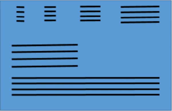
The glass sheet and metal pieces were placed as noted in the sketch in Figure 1. The glass plate was placed in vacuum laminator to reside under vacuum and the heat was applied to allow the TSSA a 30 minute soak time at 130 °C.
The purpose of the experiments was to observe the TSSA distress from the aluminum and steel attachments by viewing the TSSA through the glass. The distress by TSSA shown as whitening is an indication that the adhesive is near a failure point for loading[1]. It was expected to see a cohesive failure of the TSSA at the ends of the long spans of aluminum with 1mm thickness.
To our surprise, no failures or distress whitening were observed after the sample was removed from the laminator, however, the glass was significantly deformed. This failed experiment resulted in the idea that TSSA could be used to permanently bend glass that could then be placed into applications where a cold bent piece of glass would have aesthetic desire.
Testing protocol
Additional experiments were fabricated to validate the potential application of metal strips onto glass with TSSA to control the amount of warpage. The authors had a glass size limitation of 914 x 1524 mm due to the size of the vacuum laminator used to cure the TSSA.
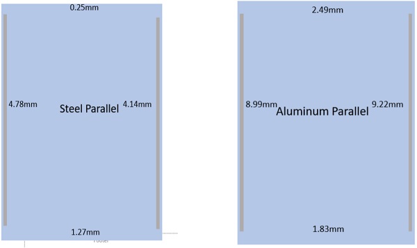
Testing commenced using parallel strips of metal on the long side of the glass as shown in figure 2.
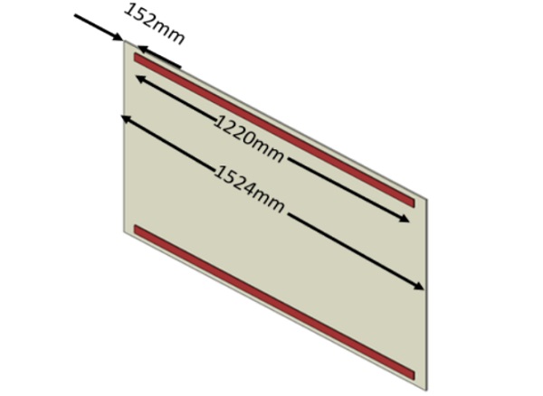
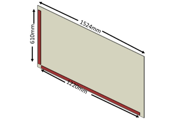
Steel strips were compared to aluminum strips in this experiment. All bonding was done with 1mm of TSSA thickness since no visual distress of the TSSA was apparent in the first failed experiment noted above.
The Parallel bonding study placed the long strips symmetrical to the center point. Hence there was an even 152mm of unbonded glass at each end. The long strips of metal were 1219mm in length attached to the 1524mm piece of glass. One piece of glass used steel strips and the second piece of glass used aluminum strips. The metal strips used in both cases measured 6.4mm x 19mm x 1219mm long.
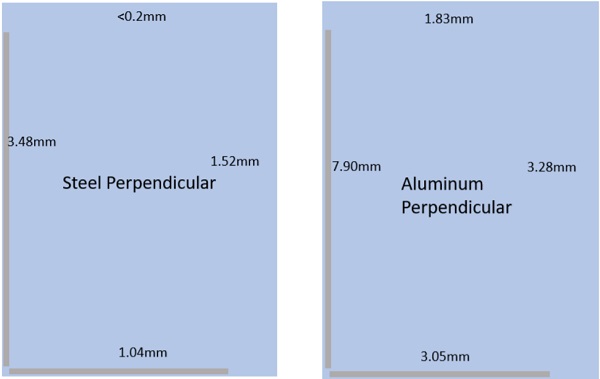
The perpendicular bonding study had the metal strips much closer to each other at the corner. This was to try and induce the maximum double bend in the corner.
After the specimens were fabricated and cured, the warpage of the glass was as expected, meaning the parallel bonding provided warpage in one direction and the aluminum strips showed more warping compared to the steel strips.
The perpendicular specimens had a double warp and again the measured warpage was greater for the aluminum compared to the steel.
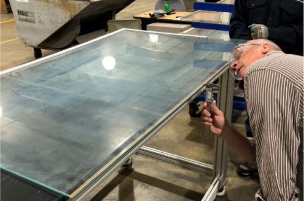
The amount of warpage was measured by placing a tight string from one corner to the other and measuring the deflection at the maximum. Figure 4 shows an example of the measurement technique. Table 1 reports the data of each panel.
Modeling of the Phenomena
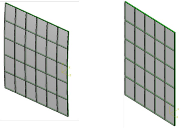
To understand the impact of different variables of the potential art, a finite element model was developed for a parallel bonding and a corner edge method. The intent of a parallel bonding method was to curve the glass only along one length of the lite where the corner edge was used to develop an elliptic paraboloid with a scallop shape through bending along perpendicular axis. (insert pics).
Important material properties for the model were modulus and Poisson Ratio for glass, aluminum and steel and hyperelastic models for the TSSA. Coefficient of Thermal Expansion (CTE) was used for all materials. Data for each material is shown in table 1 and 2.
The model was then used to predict the expected curvature of each bonding method as the assembly is cooled from 130 °C to 23 °C due to CTE mismatch of the materials.
In a design of experiments using the model, width of steel was varied between 12.7 and 38.1mm, thickness of steel varied between 3.175 and 9.525mm and thickness of TSSA was varied between 2 and 6mm.


Results of the Design of Experiments
Based on the design of experiments, the variable of the width of steel and the thickness of the TSSA has the most impact on the parallel and corner edge bonding methods. From the design of experiments, design equations can be written to determine deflection using relevant dimensions of the variables.
For the corner edge bonding, the design equation is written as follows:

Where,
Wm = Width of Metal in mm
tm = Thickness of Metal in mm
ttssa = Thickness of TSSA in mm
For the parallel boding, the variables of metal width and TSSA thickness had the most impact on the deflection. The design equation is written as follows:
![]()
Where,
Wm = Width of Metal in mm
ttssa = Thickness of TSSA in mm
The expressions can be used in a solver where variables can be iterated or held static to calculate for desired deflections.
Using TSSA to cold bend glass before final installation has unique applications for both internal and external use. This idea can be further explored using TSSA attachment points at specific locations on the glass and using cables and turnbuckles to custom or dynamically warp glass. The amount of warping can be dramatic above and beyond the adhered metal strip approach, however the cables would be a visual chord behind the arc of the glazing.
Conclusions
Due to differences in coefficients of thermal expansion, metal bonded to the surface of a glass plate can create a cold bent plate as materials cool from the autoclave process to room temperature. Increasing the width of the metal connection will increase the amount of deflection in the glass plate. Increasing the thickness of TSSA will decrease the overall deflection. A parallel bonding technique creates a bend along the length of the lite while a corner edge bonding technique creates a paraboloid shape. These shapes can be incorporated into a curved or bubbled appearance as shown in Figure 7.
This creates additional design freedom for the architectural community by incorporating cold bent glass in glass wall design. Further design options are possible by using turnbuckles and cables between traditional TSSA attachment points on the glazing. Proper engineering must be done to accommodate the stresses in the glass and adhesive so that long term durability can be maintained that enables this design freedom.
References:
1. ASTM C1048-18 Standard Specification for HeatStrengthened and Fully Tempered Flat Glass, ASTM International, West Conshohocken, PA, 2018, https://doi.org/10.1520/C1048-18
2. TSSA Data Sheet https://consumer.dow.com/en-us/document-viewer.html?ramdomVar=5471176793186186039&docPath=/content/dam/dcc/documents/en-us/productdatasheet/62/62-17/62-1709-dowsiltransparent-structural-si.pdf viewed March 7, 2019
3. Sitte, S., Brasseur, M., Wolf, A. T., Carbary L. D., Preliminary Evaluation of the Mechanical Properties and Durability of Transparent Structural Silicone Adhesive (TSSA) for Point Fixing in Glazing Journal of ASTM International, Vol. 8, No. 10 Paper ID JAI104084 Presented June 2011, ASTM Symposium
4. Clift, C., Hutley, P., Kimberlain, J., Carbary, L. D., Transparent Structural Silicone Adhesive, Glass Performance Days, Tampere Finland, June 2011
5. Carbary L., D., Clift, C., Jeske, B., Zhong, F., Airborne America San Diego, Transparency through Innovation and Engineering GlassCon Global 2016, Boston MA
6. Kimberlain, J.H., Carbary L. D., Blast Performance of Point Fixed Assemblies utilizing TSSA, Glass Performance Days, June 2017, Tampere Finland
7. Kimberlain, J.H., Carbary, L. D., Dull, B., TSSA: Performance in Hurricane Impact Applications, Glasscon Global 2018, Chicago IL,
8. Santasario, M., Louter, C., Lebet, J-P., The mechanical behavior of SentryGlas® and TSSA laminated polymers in cured and uncured state in uniaxial tensile test, Challenging Glass 4 COST Action TU0905 Final Conference , Louter, Bos, Belis & Lebet (Eds), 2014 Taylor & Francis Group London
9. Kassnel-Hennenberg, B., Connections in Glass, Challenging Glass 5, Conference on Architectural and Structural Application of Glass, Belis, Bos & Louter (Eds),Ghent University, June 2016
10. Hagl, A., Dietrerich, O., Wold, A. T., Sitte, S., Tensile loading of Silicone Point Supports – Revisited, Challenging Glass 3 – Conference on Architectural and Structural Applications of Glass, Bos, Louter, Nujsse, Veer (Eds), TU Delft, June 2012
11. Carbary, L. D., Ludvik, M. A., Lencus, A., Zhong, F., Field of Rods, Culver City Californina: TSSA Design and Mock Up Performance, Glasscon Global 2018, Chicago IL
12. http://defineengineers.com/project/gravity/viewed March 7, 2019


