Architectural Glass Laminating Guide - Part 4
By Luc Moeyersons
A look at the roller process.
Oven – Heating concepts:
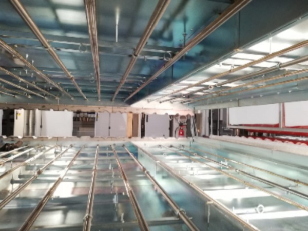
Convection (circulating air):
- The glass is heated.
- The PVB is heated by thermal conduction through the glass.
- Positive/negative points:
- Not sensitive to (IR-reflective) glass coatings
- Slow process
- Heat transfer depending on glass mass/thickness
Long wave IR radiation:
- The IR heats the glass: the PVB is heated by thermal conduction.
- Radiation does never occur on its own, oven heats up and creates convection heat.
- Positive/negative points:
See further in this chapter.
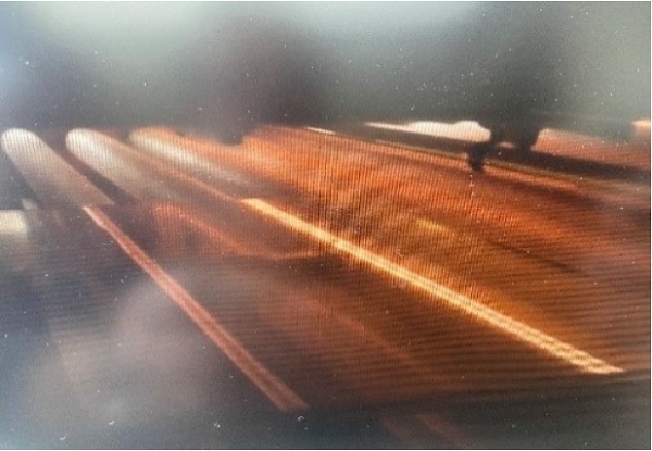
Short wave IR radiation:
- The glass is transparent to IR waves with a frequency till 3.5 µm.
- The PVB is not transparent at frequencies of 2.7µm.
- The PVB is heated through radiation.
- (Differential) heating from top and bottom necessary.
- Positive/negative points:
See further in this chapter.

Micro-waves:
- Possible in theory, but not yet developed commercially.
- Issues: temperature accuracy, large surface heating, time and temperature control.
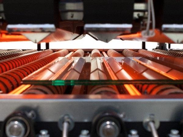
Infra Red Heating concept

If one looks at absorbance scans of the interlayer sheeting, one can notice that around 3.5 microns (3500 nanometers) PVB and other interlayers/inserts absorb energy while glass transmits this energy.

If one would look at transmittance, one would see that glass (regardless of the color) transmits app. 30 % of this specific IR energy, whereas PVB would transmit less than 10 % at this specific wavelength.
Correct IR-radiation:
Translated to a lamination heating process, with (correct) IR heating elements above and below the laminates, and based on thermocouple appreciation, one would expect when 4 mm glass would be used and an interlayer of 0.76 mm, the glass to absorb app. 70 % of the energy, 20 % at the PVB/Glass interface and 10 % by the PVB.
Not correct IR-radiation:
Using short wavelength IR elements (radiation peak around 1.5 micron), most of the IR energy would pass through the glass and the PVB. This would mean that a lot of energy would be lost inside the oven, being absorbed by all possible elements and converted into convection energy/heat.
One can assume that 20 % of the infrared energy would be absorbed by the glass, 5 % at the PVB/Glass interface, 5 % by the PVB and 70 % would pass through the laminate, changing into convection energy. Note that convection heating is a slower process than radiation.
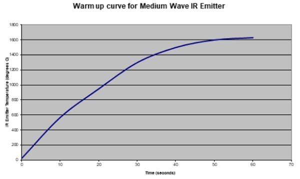
The IR element providing this concentrated IR radiation peak around 3.5 micron (2.5 to 4.5 micron) would be a “Fast Response Medium wavelength element” (3.5 to 6 micron) at a 90 % of the maximum element emitting/burning rate (1400 °C versus 1600 °C).
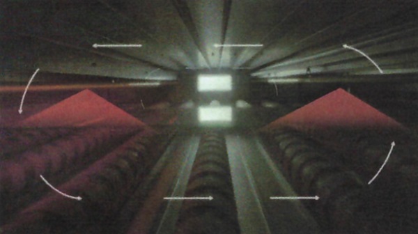
The wavelength of IR elements is set by the “IR emitter temperature”, so medium wavelength elements could be tuned to 2.5-to-4.5-micron wavelengths by influencing the “IR emitter temperature” or reducing the electrical power supplied to the IR element. In my opinion medium wave IR elements would provide the best equilibrium between radiation efficiency and output.
The company Heraeus has developed (together with twin tube IR emitters), a system to control radiation of IR elements, called Herathron Thyriston Power Controllers.
This system allows to link the temperature of the radiated element to the process control.
Experiments have been run, where IR elements were operating under 90 % of the electrical power to ensure proper radiation and elements reduced to a 60 % level, when no laminates passed through the oven.
This also ensures a very rapid response to increase to the right electrical energy level, where it takes a much longer time (4 to 5 times) for an IR element (starting from 0) to reach close to maximum “IR emitter temperature”.
Herathron, if properly installed, also allows a different radiation top to bottom.
This helps to provide equal energy from both sides, despite the fact that conveyor rollers will continuously absorb/reflect energy.
On the other hand, this system will help to process asymmetric laminate construction, in caliper, color and even with coatings.
Herathron also allows a much better controlled electrical energy level and as a consequence a better controlled and focused IR-radiation.
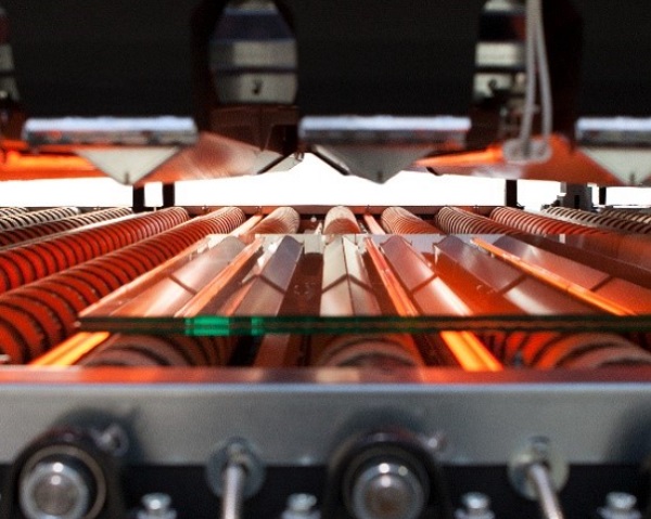
Another important point is the equilibrium between IR radiation and convection.
Most IR oven construction companies are using oven temperature (convection) to steer the IR radiation.
To do this they have a series of IR elements (usually in couple, one above and one below the laminate path) that are continuously on and then a few that will switch on and off depending on the oven temperature.
This action will change the equilibrium between convection and radiation.
Successful trials were run by opening the chimneys on top of each oven section and let heat (convection) out.
The opening of the chimneys should be steered in such a way that all IR-elements are continuously on, without massive loss of convection heat. This is not the most energy friendly way but allows initial setting at start up or defining process conditions.
Ventilators inside the oven section will also help to create a uniform (convection) heat.
Another way of controlling the radiation/convection equilibrium could be to have a switch installed on the assembly conveyor at some distance from the oven. This distance should be equal or more then (60 seconds) the time needed for the assembly stack to pass into the oven and all IR elements being in full radiation.
Roller line concept:
Conventional system – 2 ovens and 2 rollers


The first (pre-)oven has to heat up the glass/PVB sandwich till approximately 35° C to allow evacuation of air with the PVB (surface roughness) being in the plastic deformation temperature.
Nip roller pressure:
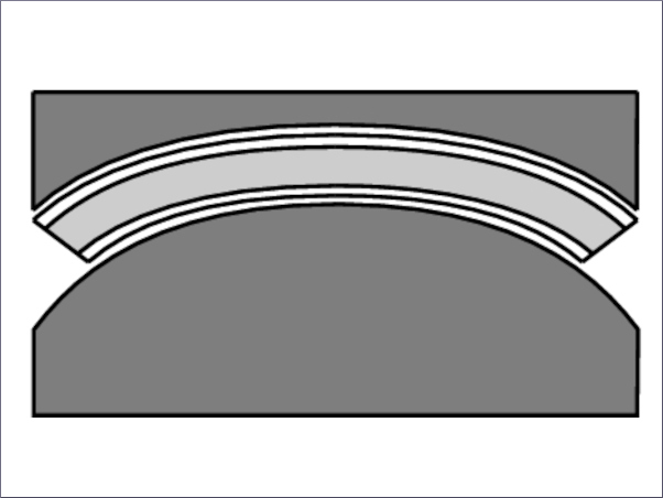
There are 3 (commercial) ways of applying pressure to the nip rollers:
- Pneumatic cylinders
- Hydraulic cylinders
- Servo-spindle press cylinders
In all cases the cylinders on both sides of the nip rollers are interconnected (communicating vessels), this to ensure equal pressure on both sides of the nip rollers.
Pneumatic cylinders:
2 pneumatic cylinders are applying pressure (bottom nip rollers on fixed axe position, top nip rollers equipped with pneumatic cylinders) to the top nip rollers.
Pressure on both pneumatic cylinders is between 3 and 7 bar.
When asking European laminating line producers about the diameter of pressure cylinders used (to calculate the actual pressure at the nip rollers), I obtained mixed answers (actual data, vague answers, relating to confidential information,...).
But most suppliers use 3 to 7 bar pressure on the cylinders.
Hydraulic cylinders
2 hydraulic cylinders are applying pressure (bottom nip rollers on fixed axe position, top nip rollers equipped with hydraulic cylinders) to the top nip rollers.
Pressure on both hydraulic cylinders is between 3 and 7 bar. (one supplier uses 19 bar but with a much smaller set of pressure cylinders )
Servo-spindle press cylinders
2 servo-spindle cylinders are applying pressure (bottom nip rollers on fixed axe position, top nip rollers equipped with servo spindle cylinders) to the top nip rollers.
This system is claimed to be more precise and consistent.
The maximum nip pressure is 25 kN/meter laminate width and is calculated automatically relating to the glass/laminate width.
e.g. at an 44.2 PVB the pressure is 22 kN/meter glass width (ᵙ 110 N/cm2 contact surface); is the laminate 2 meter wide, then the total press force is 44kN onto the laminate sandwich.
The pressure of nipping should be (in most cases) between 100 and 150 N/cm2 (goal 125 N/cm2). This way the rubbery cover of the nip roller is deformed by app. 2 cm (nipping width). To obtain this deformation with that pressure a rubbery cover hardness should be 60 – 80 Share A. For most nip roller lines that means a pressure on the cylinders pushing the rollers together of 3 to 5 bar (depending on the cylinder diameter)
Remains the gap (aperture/opening setting) of the rollers: This should be 1 mm less than the glass thickness of the laminate (using single laminated annealed glass). This can be reduced by 1 mm more for tempered and heat strengthened glass.
For multi laminated glass, a reduction of 1 mm per glass lite should be sufficient.
Again, tempered and heat strengthened glass can stand more roller deformation/pressure by a reduced roller gap.
The second oven should heat up the laminated glass till around 60° C, to allow the second nip rollers to seal the edges of the laminate, so that no (compressed) air can come into the laminate during autoclaving.
Nip roller settings should be identical to the first nip rollers, but pressure can be increased till 3 to 7 bar.
The laminated glass temperature settings (above) can be slightly different depending on the PVB type/PVB rheology/PVB surface roughness.
Simplified system - One oven and one roller.

Here the (second) nip rollers need to perform both actions: de-airing as well as edge sealing. This means that the process needs to be run slower (the shorter oven with less IR heating elements will already require to run slower, to reach the needed temperature.
One could also decide to pass the laminate-sandwich twice through the oven and nip rollers, but it might be more complicated to reach the target temperature (1st time: 35° C and second time: 60° C).
One oven and 2 rollers.

If the glass/PVB temperature is not at 35 C, these first nip rollers will not be able to adequately de-air the PVB-glass sandwich. The PVB will still be in the elastic region temperature and as a consequence the glass laminate (especially with thin glass) might open in the oven due to the pressure applied (in the middle of the laminate length) by the first roller. The hot air, that entered into the laminate, will not be able to be removed.
One will notice “clouds” in the pre-nip or “leopard skin” (zones with increased opacity with a clear periphery – due to air bubbles below the PVB that are flattened by the pressure and a slightly thicker PVB at the periphery of the air pocket will be squeezed resulting in a slightly thicker PVB and clearer prepress periphery).(laminating defects: see further)
Laminating processes with one oven or one roller, work adequately till a processing speed of app. 8 meters/minute.
If a first pre-nip temperature of 35° C cannot be reached, it is advisable to open the first nip roller to a gap equal or larger than the laminate thickness. When set equal to the laminate thickness, the nip roller will/should remove possible PVB wrinkles.
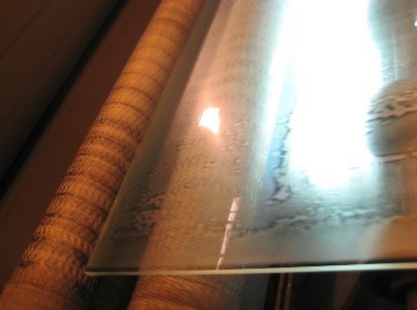
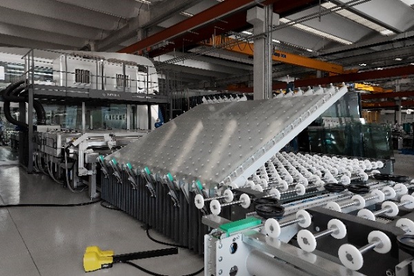
Pictures are shown with reference to the source of the picture.
If the info is wrong, please contact author with correct info for document correction.
This information corresponds to our current knowledge on this subject. It is offered solely to provide possible suggestions for your own experiments. It is not intended, however, to substitute for any testing you may need to conduct to determine for yourself the suitability of our advice for your particular purposes.


