This paper was first presented at GPD 2023.
Link to the full GPD 2023 conference book: https://www.gpd.fi/GPD2023_proceedings_book/
Authors:
- Dr. Klaus Mühlhans – A+W Software GmbH
- Kai Vogel – Viprotron GmbH
Abstract
Digitizing templates has always been cumbersome. Templates are used quite often to define non-rectangular (shaped) glass sheets. Unfortunately, they cannot be used directly for production but need to be converted into a digital representation (typically a sequence of arcs and straight lines). To do so, they are quite often transported long distances to a production facility.
A joint development by Viprotron and A+W Software combining image processing and mathematical (geometry) knowledge resulted in a new digitizing method at ease: Using mobile devices like mobile phones or intelligent scanners to take pictures from templates in combination with reference objects.
The advantages are multifold. Using standard devices at hand plus some specific reference objects, pictures may be taken anywhere. Processing takes place in the cloud and the final geometry is derived in the production facility.
There is no need to send templates around reducing transport costs and speeding up processes.
Introduction
The need to digitize non-rectangular (shaped) geometries in glass processing is existing since there are machines capable of processing those geometries based on data. Decades ago, quite large and heavy mechanical digitizing tables were used to acquire those data. They required a lot of space and the process to digitize the typical wooden templates were quite complicated. In addition, those tables are not available on the market anymore.
Hence, alternative solutions came up in the market each having their own advantages / disadvantages (wire based measurement: Proliner by prodim-systems.de / calibrat-ed camera based measurement: Virtual Digitizing by LiteSentry/Softsolution glasquality.com / cutting table to digitize templates using a sensor pin instead of the cutting wheel). All these solutions require annual recalibration, templates that need to be transported or are simply too expensive to equip each sales person with such a device to be able to carry it with them on customer visits.
Having this situation in mind, an easy to handle solution using existing tools and avoiding costly transport of templates is needed motivating a joint development by Viprotron and A+W to provide mobile digitizing at ease: iShape.
How to digitize using existing tools?
The natural way to recognize an object today is to take a picture. Hence, a camera is the correct tool. Today, all state of the art mobile phones are providing cameras having excellent resolution. In addition, and better suited for production environments, the latest generation of intelligent mobile scanning devices are providing cameras at high resolution as well. Getting a usable image of the object to digitize, therefore, should be possible at acceptable effort (clearly, light conditions, distance to object, tilting and background have to be considered).
Unfortunately, every camera is imposing optical distortions being specific to the individual camera. Hence, some kind of calibration is necessary to compute an undistorted picture. As it makes no sense to calibrate each camera individually (having the aim to use already existing tools at hand), we need to place reference objects into the image to allow a dynamic processing of images. The resulting process follows these steps:
- Place the object (template) on a well-suited background (gray felt, for example)
- Place a considerable amount of reference objects onto the template
- Take a picture (following some simple rules)
- The picture is, then, sent into a cloudbased processing tool
- The cloud-based processing generates an undistorted, properly scaled picture and a sequence of dots along the objects outer perimeter
- Take the result from the cloud and process it in A+W CAD Designer to convert the dotcloud into a proper sequence of arcs and straight lines
- Output the result into machine instructions or DXF output for further use
Details about these steps will be provided below.
Suitable background
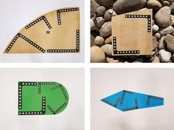
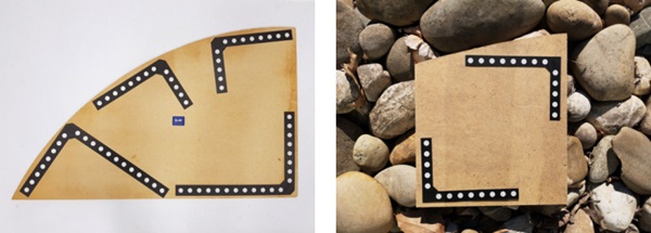
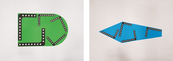
The background should be as homogeneous as possible and in good contrast to the respective objects. See pictures.
Reference Objects
We are using L-shaped rulers as reference objects. Those rulers carry several circles having precise locations and dimensions. A set of different sized rulers is provided to cope with the typical variation of template sizes. A few examples of well placed rulers are in Figure 2.
It is crucial for the measuring accuracy that these L-rulers are manufactured precisely, since the contour measurement depends directly on the accuracy of the calibration of the camera distortions carried out in the image with the L-rulers.
Pictures
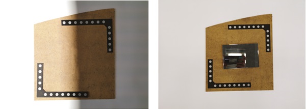
It goes without saying that some care is required to provide a well-focused non-blurry image.
Cloud-based processing
Once taken, the picture is automatically sent to a Cloud-based processing tool. As a result, the app on the mobile device will show the amount of reference objects detected and a dashed line following the object's perimeter. In addition, a quality factor is computed and presented. In combination, those information guide the user to judge if the image taken was good enough or needs to be redone.
Final processing within A+W CAD Designer
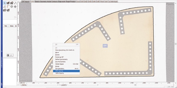
The final result of processing is transferred into A+W CAD Designer for final processing. Within CAD Designer, the undistorted picture and the resulting shape defined by arcs and straight lines are presented for further inspection and/or modification. In most cases, the algorithm will directly provide a usable result. Given templates being quite often damaged in some areas the ability to correct the contour based on the undistorted image is extremely helpful. In addition, internal contours like cutouts and drills may be applied manually based on the picture.
Summary
Digitizing templates has always been cumbersome. Using the A+W iShape, this process is now at ease. With the help of reference objects and proper background and light conditions, all steps related to digitizing are now easier to handle. Pictures may be taken at any location, likely at a construction site as well whereas the final processing is happening in the cloud and in the final production location.
Thus, the A+W iShape solution makes it very easy for a sales team to take pictures of the models directly at the customer's site with their own camera and send them to the company via the cloud. There, the corresponding glass can be produced straight away. Nothing has to be planned in advance or transported in a cumbersome way. Only the L-rulers have to be packed, which are neither heavy, expensive nor require considerable space.

