Article Information
- Digital Object Identifier (DOI): 10.47982/cgc.9. 532
- Published by Challenging Glass, on behalf of the author(s), at Stichting OpenAccess.
- Published as part of the peer-reviewed Challenging Glass Conference Proceedings, Volume 9, June 2024, 10.47982/cgc.9
- Editors: Christian Louter, Freek Bos & Jan Belis
- This work is licensed under a Creative Commons Attribution 4.0 International (CC BY 4.0) license.
- Copyright © 2024 with the author(s)
Authors:
- Stefan Trifonov a
- Andrea Pilla a
- Fangliang Chen b
- Tejav DeGanyar b
a Schüco UK Ltd., UK
b Virtual Construction Lab of Schüco, New York, USA

Abstract
Sustainability, and more specifically embodied carbon emissions, have become one of the most prominent challenges for the facade industry. Discussions around the topic focus on the global warming potential of materials and their recycled content, whilst efficiency and innovation in design as a way to reduce embodied emissions have not yet received the same level of attention. This article proposes evolved structural design and detailing methods for glass-metal facades that minimise the amount of materials needed to meet their serviceability and structural integrity requirements. The discussion focuses on structural sealant glazing and the composite behaviour of glass and frame to resist out of plane loads. The study promotes capitalizing on the inherent contribution of the adhesive connection towards the flexural stiffness of façades and proposes ways of enhancing it for further structural optimization. The impact of the adhesive connection is assessed through an experimental program consisting of extensive four-point bending tests of representative beam samples and corresponding numerical studies. The article provides an interpretation of the interim results and discusses the potential of the proposed solutions to contribute towards a holistic approach to reduce the global warming potential of building envelopes. Finally, directions for future research needed for practical applications of the proposals are presented and discussed.
1.Introduction
1.1. Current façade design practices in the context of a drive towards sustainability
Since the advancement of modernist architecture in the early 20th, building envelopes have evolved tremendously and the concept of the curtain wall has established itself as a widely used construction technology, (Schittich, et al., 2007), (Thomas, et al., 2018). Both stick and unitised systems are widely used, with the latter quickly increasing its popularity and market share due to the benefits of off-site fabrication. In terms of the glazing, structural sealant glazing (SSG) systems have become very popular and established themselves as a coequal alternative to captured glazing.

Since the oil crisis of the 1970s and the resulting rise of energy costs, the thermal performance of curtain walls and facades in general has been steadily improving. Whilst this trend has clearly beenbeneficial for operational costs and operational emissions, the topic of embodied emissions in facades and buildings as a whole was not in the public’s attention with the same prominence until several years ago. This has however been changing, especially since the historic Paris agreement (Nations, 2015). The emissions targets to counteract climate change set out in this document and others influenced by it have had a profound effect on the façade industry. The global warming potential of facades, and thus their embodied carbon emissions are now a key consideration in the design and procurement of curtain walls, alongside the well-established thermal performance criteria.
To address the drive for reduced embodied carbon emissions in facades, the industry has turned to material offers with a high recycled content, i.e. materials whose bulk has already undergone their virgin processing and thus require much less energy to be reprocessed and turned into new products.Whilst it is clear that recycling must be used to its maximum potential, it is becoming ever more apparent that it alone is not sufficient to meet the targets. This is due to the limited resources available to urban mining in an environment of a globally rising demand. It is thus imperative that other innovations are found so that the material use in curtain walls can be reduced and thus the rise in the demand be softened, to complement the efforts made with recycling and low carbon energy.
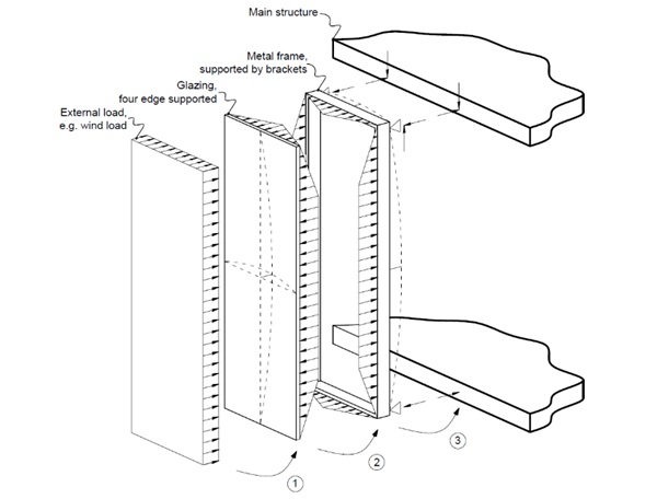
In contrast with the discussed developments in materials and the efficiencies in design and manufacturing, the structural design of conventional curtain walls has comparatively lagged behind. Whilst the understanding of structures and the capabilities of finite element method software have certainly been profoundly improving, the fundamental structural concept of a glazed curtain wall has not evolved significantly, see Fig. 2. Facades are almost exclusively designed without considering any combined or composite structural interaction between glazing and frame.
Whilst this simplified structural hierarchy of components offers benefits in terms of speed of calculation and separation of trades, physical tests of real façade systems often show that they are significantly more rigid than their analytical models. This is especially valid for SSG curtain walls, which benefit from the stiffening effect of the shear coupling between the glazing and the frame, as provided by the adhesive.
The research presented offers ways to utilize the existing composite behaviour of SSG facades and amplify it with additional new measures, to make bonded assemblies more structurally efficient and thus reduce significantly the required amount of aluminium. As a result of using the proposed concept, the embodied carbon emissions in unitised curtain walls can be significantly reduced.
1.2. Description of the proposed design and detailing concept
The theory of composite structures and its applications for structural optimization has been used successfully in construction for decades. The benefits of the phenomenon are used extensively, for example in composite steel-concrete slabs, (Anon., 2024) and are well documented in various codes of practice, e.g. (CEN, 2005).
In terms of the building envelope industry, composite behaviour is predominantly used in lightweight enclosures utilizing sandwich panels. The structural behaviour of such panels subjected to bending is based on the classic sandwich theory and is well understood, e.g. (D., 1995). In glazed enclosures however composite structural behaviour is not typically used and façade assemblies are usually designed in accordance with Fig. 2.
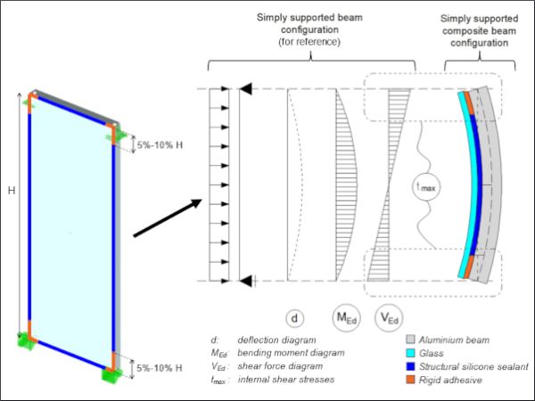
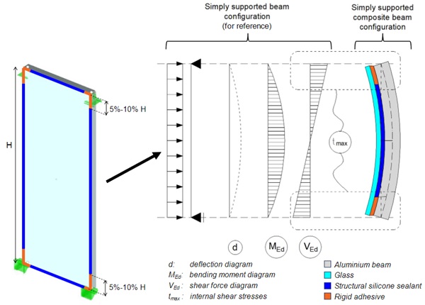
The proposed “minimal wall” concept aims to change this and utilise principles of “composite structural behaviour”. It will be used in SSG assemblies, predominantly in unitised façades, whereby all bonding can be carried out off site. To minimize the sections of the metal frame, the inherent shear transfer between glass and metal will be used and, as an option, further enhanced by a secondary adhesive applied to the corners of units. The location of the second, more rigid adhesive is chosen in line with the expected peak shear stresses in a conventionally supported unit subjected to an out of plane load, see Fig. 3.
In terms of their flexural bending, members constructed in accordance to the minimal wall principle will exhibit partial composite behaviour, see Fig. 4. A full composite behaviour, i.e. full shear transfer between glass and aluminium is undesired for several reasons, e.g. expected excessive bending due to differential temperatures and stress concentrations.
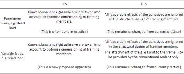
The rigid adhesive associated with the enhanced partial composite behaviour is introduced locally. This means that the SSG unit will remain predominantly conventionally bonded. This circumstance is beneficial, as the safety concept of the system in terms of ultimate limit states (ULS) can be maintained exactly as current systems with a traditional level of conservatism. The rigid adhesive proposed will only be used for structural optimization in terms of serviceability limit states (SLS), which is usually critical in terms of sizing the framing members, see Table 1.
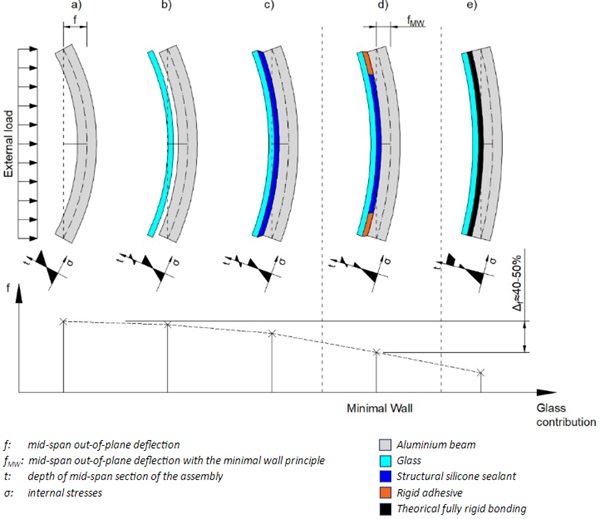
Table 1: Proposed safety concept for façade units with enhanced partial composite behaviour (minimal wall concept).
1.3. Overview of standards and relevant previous research
As described above, it is still common industry practice to assume that all external loads are carried by the framing when checking the capacity of structural sealant glazing systems subjected to out-of-plane loads. However, at the same time, it is widely recognized that there is a shear coupling between glass and frame in structural glazed facades. Indirectly this is also recognized by the product standard (BS EN 13830, 2015) that states that when calculating the rigidity of the curtain walling, the potential stiffening effect of the glass should be neglected, unless adequate calculations of the glass contributionare provided. In addition, physical tests, carrying out by Schüco during years of experience, have shown anecdotally that SSG facades tend to consistently undergo smaller out-of-plane deflections during teststhan values estimated through calculations without considering glass contribution in the stiffness of assemblies.
In the research sector, (Overend M., 2013) have demonstrated in 2013, that adhesive connections exhibit higher load-bearing capacities than equivalently sized bolted connections. Indeed adhesive connections generate smaller stress concentrations than bolted connections and, in addition, do not involve weakening of the glass due to drilling and difficulties in toughening glass in the area of a bolt hole (Laufs W., 1999), (Nielsen J., 2010).
Some previous studies demonstrated that glass panels linearly bonded to profiles by high strength adhesives are able to achieve composite action when subjected to flexural loads and exhibit significant post-fracture strength. (Nhamoinesu S., 2014) and (Pascual C., 2019) worked with medium-scale (700mm×300mm) and large-scale (3500mm×1500mm) steel-glass composite units subjected to out-of-plane loads. The units consisted of two glass panes with rectangular steel profiles between thempositioned either only along their longitudinal edges or both along their longitudinal and transversal edges. Similarly (Pascual C., 2017) (Gargallo M., 2021) tested composite sandwich panels made of glass face sheets adhesively-bonded to a centred core profile in glass fibre-reinforced polymer (GFRP). Theuse of moderately stiff adhesives in the investigated GFRP-glass sandwich beams leads to a composite action (in terms of deflection) of 95% in comparison to the predicted composite action of 16% for the same beams with common low shear modulus structural silicones.
More broadly, the structural application of sealants in SSG facades is studied more extensively with regards to the behaviour of bonded assemblies under in-plane loads (Silvestru V., 2019), (Alcaine J., 2020)
Unlike the referenced studies, the proposed minimal wall concept focuses on harnessing the innate stiffness potential of conventional SSG assemblies and proposes a new, hybrid two-adhesive model for its enhancement.
1.4. Methodology of assessment and scope of the research
Experimental and complementary FEM studies were carried out as the means to assess the viability of the concept.
The experimental study included forty beam samples subjected to four point bending tests. The specimens represented primary members from a unit, e.g. a vertical frame, with their tributary glass width, subjected to bending from a normal load.
The goal of the program was to assess the viability of the proposal through studying the bending behaviour of a composite beam in isolation, in particular the contribution of partial composite behaviour towards the overall stiffness of the member and indirectly the unit it belongs to. The samples were designed to be symmetric and as simple as possible, so as the study could focus purely on the composite behaviour of the different types of beams without the effect of any “polluting” factors, e.g. eccentricities, bonding strips etc. The size of the aluminium section and the tributary glass component were selected to have broadly the same stiffness ratio as a real life SSG member.
The sample types had different configurations in terms of sealant selection and length of the secondary rigid adhesive. Each sample series, except series #1, included a minimum of five specimens, to enable the statistical analysis of the obtained results. Series #1 samples were simple rectangular hollow section beams without any glass or adhesive. Series #1 thus represented the status quo in terms of structural design methodology, i.e. no contribution from glass or sealant, and was the baseline with which all other series would be compared.
All samples were tested under four-point bending and loaded until a recorded maximum midspan deflection was reached. Particular attention was paid to the loads resulting in corresponding to deflections of span/200 (~15mm) and span/ 60 (~50mm), which are considered SLS and ULS design scenarios, respectively. Despite the fact that past the SLS threshold the composite behaviour will not be used in structural design, all samples were loaded to a deflection equal to approximately span/60. This deflection is considered an indicative ULS threshold, in line with the “excessive deformation” definition of (CEN, 2005). The decision to test the composite samples past the proposed scope of application of the composite principles (i.e. SLS) was made in order to demonstrate their robustness and post-critical behaviour.
One specimen from each series was tested past the point of the span/60 deflection and to destruction. The findings from these tests are outside of the scope of the current study, which will be investigated later with the support of further material characterizations of the secondary stiffer adhesives.
The complementary FEM studies included volumetric models of the tested samples built with currently available material data to enable a comparison with the test results.
The scope of the current stage of the study is limited to the following:
- Identify the contribution of partial composite behaviour in SSG members towards their overall bending stiffness in serviceability limit state scenarios;
- Assess different bonding layouts and the efficacy of using two different materials in one member, i.e. conventional structural silicone and rigid polyurethane adhesive;
- Compare key results from the tests carried out with FEM models based on available material data, to provide initial guidance for future structural design practice. The study was carried out with the help and advice of Sika AG.
2. Experimental study
2.1. Description of the specimens and test method
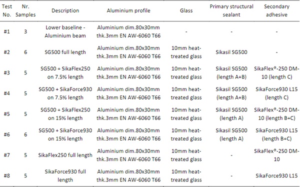
An overview of the samples, including the adhesive configuration is provided in Table 2.
Table 2: Summary of the specimens tested.
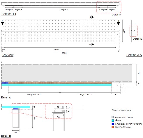
In all specimens, the metal component was an extruded aluminium beam grade EN AW-6060 (AlMgSi0,5) F22 T66, 3150mm in length, with a section of 80mm x 30mm x 3.0mm, anodized in (E6/C0).
Monolithic 600mm x 2970mm glass panes with 10mm thickness were selected for all samples. All glass panes were heat-strengthened, with the exception of one specimen per series which used toughened glass, for the samples to be loaded to destruction.
Seven different configurations of primary structural sealant and secondary adhesive were evaluated.The structural silicone used in samples of series #2, #3, #4, #5 and #6 was Sikasil® SG-500, a common structural glazing sealant in SSG systems. The secondary adhesives tried in the program were two polyurethane based products- Sikaflex®-250 DM-10 and SikaForce®-930 L15 were used in these tests.
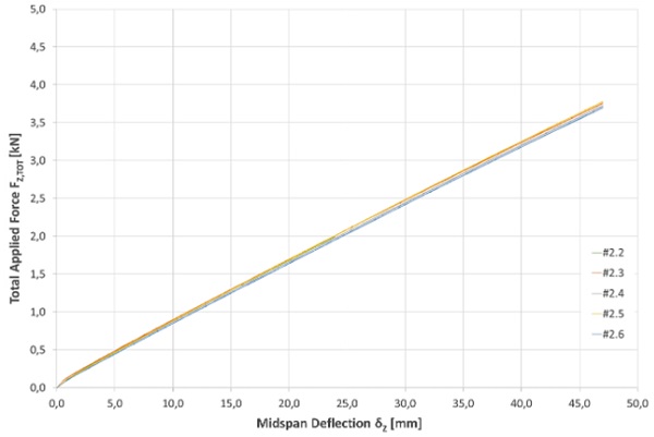
Samples of series #2 were bonded entirely with conventional structural silicone, i.e. Sikasil® SG-500. These samples represent conventional SSG systems as they are typically built, although their partial composite behaviour is not normally considered in the design.
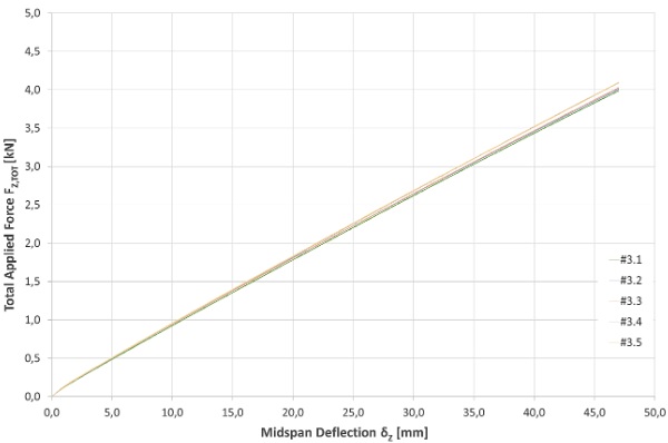
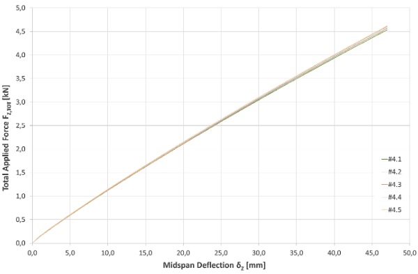
Samples of series #3 and #5 featured Sikaflex®-250 DM-10 at both ends of the beam for 7.5% and 15% of the overall length of the span respectively and Sikasil® SG-500 for the remaining areas. Specimens of series #4 and #6 reflected the same arrangement but with SikaForce®-930 as a secondary rigid adhesive.
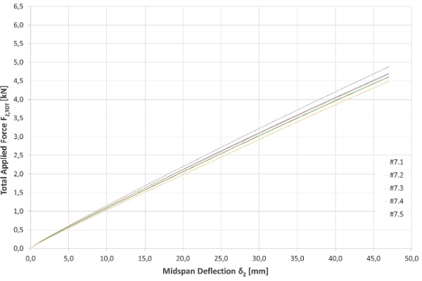
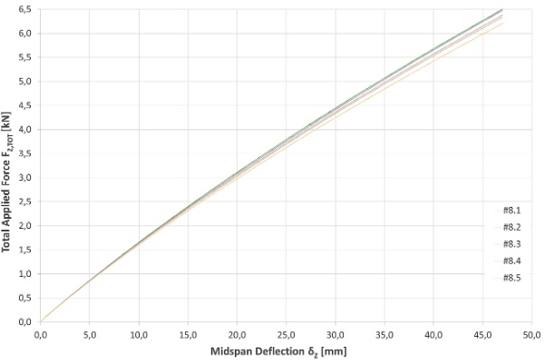
For completeness, two of the sample series were bonded with polyurethane adhesive only. Samples of series #7 were bonded entirely with Sikaflex®-250 DM-10. Samples of series #8 were bonded entirely with SikaForce®-930 L15.
Table 3: Summary of the properties of the used adhesives (information provided by Sika AG).
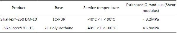
The material characteristics referenced for both adhesives were presented as initial values under room temperature conditions as provided by Sika AG, on the basis of in-house adhesive testing. More thorough material characterisation under different conditions will be developed in the further stages of the development.
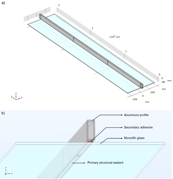
Prior to the application of adhesives, the surfaces of the aluminium bars were pretreated thoroughly according to procedures provided by Sika. These included cleaning agent, solvent-based adhesion promoter or primer as well as partial abrasion of the aluminium where the polyurethane was applied.Sika is working on improved procedures for practical applications. In all samples, both the primary structural silicone and the secondary adhesives, have a 19mm bite and 6mm thickness. To allow a centred bite and avoid potential eccentricity effects, a 6x6mm glazing tape was applied at one edge of the anodized beams and the adhesive was applied with a recess of 5mm from the opposite edge, as shown in Fig. 5. The consistency of the recess between tests was guaranteed by a special 3D printed tool that removed excess sealant in the joint. Both the primary structural sealant and the secondary adhesive were applied and cured according the guidelines from Sika, prepared specifically for the prototypes.
Following Sika’s instructions, in samples with two types of adhesives, the polyurethane glue was applied twelve hours before the structural silicone. This was to allow curing and eliminate potential compatibility issues in the interface between different adhesives.
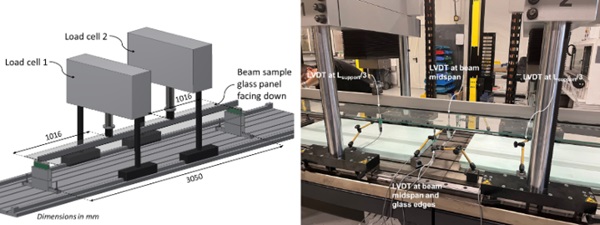
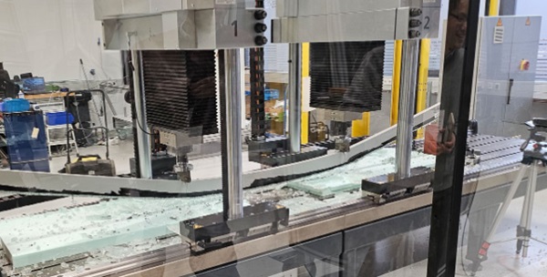
All beam specimens were tested under four-point bending following the recommendations set out in (ASTM, 2016), with a supporting span of 3050mm and a loading span of 2033mm, see Fig. 6. The tests were conducted in a room with controlled environment (T=23±2°C and RH=50±5%), with displacement control at a constant rate of 5mm per minute. The testing equipment used was a DYNA-MESS Universal Testing Machine E fitted with load cells of 50kN. The deflection at the midspan was measured with aGEFRAN linear variable differential transformer (LVDT) type PY-2 -C -050 with a 50mm spring. However, due to the required initial compression of the spring of the LVDT, the maximum measurable deflectionwas 47mm in the LVDT. Additional LVDTs were installed to control the progress of the bending and any undesired rotation of the sample.
During the bending test, the applied load by the two load cells and the outputs of the LVDTs were recorded at a rate of 100Hz sampling frequency using a proprietary data acquisition system provided with the testing machine.
2.2. Test results
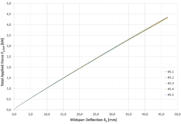
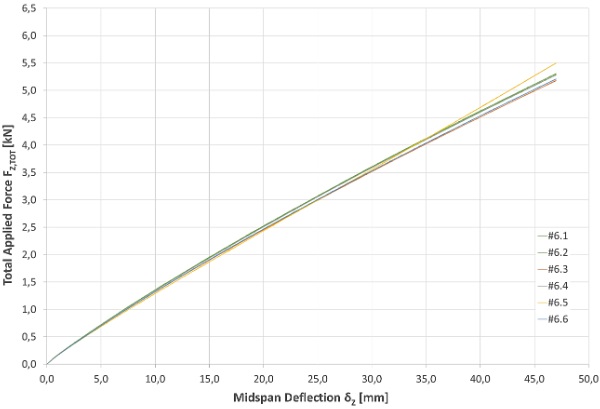
The load-deflection (p-δ) curves obtained for all test series are reported in the following figures. In the graph of each series, the curves of all tested specimens up to a deflection of 47mm (approximately span/60) are presented. Each specimen was loaded until its deflection reached the maximum measurable deflection (~47 cm) and then unloaded, except for those samples in each series loaded up to failure. However, the post critical behaviour of the samples is outside of the scope of the current investigation. It is thus not included in the presented graphs.
2.3. Summary on the experimental study
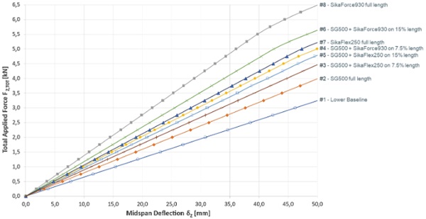
The average load-deflection curves for all sample series are presented in Fig. 14.
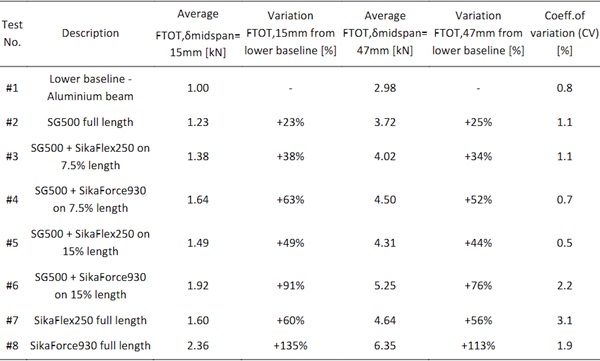
A comparison of the loads required to achieve the two monitored thresholds, i.e. span/200 (indicative SLS, δMIDSPAN=15mm) and span/60 (indicative ULS, δMIDSPAN=47mm) are presented in Table 3.
The following summary can be made on the basis of the obtained results:
- Taking into account the innate shear transfer provided by the standard structural silicone can result is an increase of the load applied to achieve the same deflection as the baseline of more than 20%
- Sample series #5 with SikaFlex250 at 450mm (15% of the beam length) at each side of the beam and standard structural silicone in the remaining joint demonstrated an average improvement in applied force of 49% at the serviceability limit state in comparison to the baseline.
- Sample series #6 with SikaForce930 at 450mm (15% of the beam length) at each side of the beam and standard structural silicone in the remaining joint demonstrated an average improvement in applied force of 91% at the serviceability limit state in comparison to the baseline.
- Varying the length and the material, i.e. shear modulus, of the secondary adhesive is an effective means of controlling the overall stiffness of the hybrid assemblies.
- Bonding the full length of the glass with SikaFlex930 leads to a force increase of 135% in comparison to the baseline.
- As evident in Table 3, the results across all samples are consistent (coefficient of variation between 0.5% and 2.2% for sample series #5 to #6.
- The coefficient of variation for sample series #7 to #8 was marginally higher. However, this may be due to slight inconsistencies in the adhesive application on the prototypes. Moreover, these series were included in the program for completeness and to add indicative upper bounds, without an intend to use in practical applications.
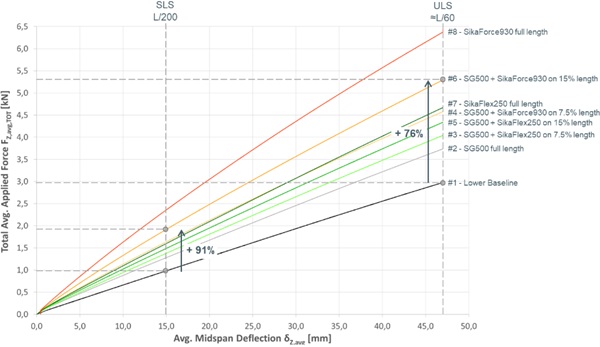
Table 4: Results of the four-bending tests carried-out for the different series.
3. Numerical study
3.1. FE methodology and assumptions
COMSOL Multiphysics® was used to conduct a finite element (FE) analysis to correlate the simulations to the experimental results. The comparison had two purposes:
- Calibrate the tests for an overall understanding of the test results
- Facilitate the FE models for future thorough parametric studies to gain insights into crucial design parameters of SSG.
Table 5: Basic material properties for FEM analysis with volumetric elements.
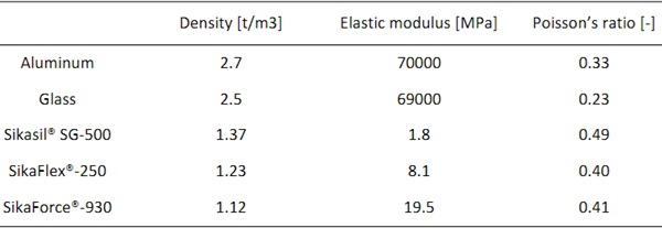
For the simulations in COMSOL Multiphysics®, volume elements and linear elastic material laws for silicone and adhesives were applied in the simulations, as summarized in Table 4. The decision to model the adhesives as elastic materials was necessitated by incomplete material data on all materials.
The aluminium extrusions were modelled as an elastic-plastic material, where an isotropic hardening rule is used and a tangent modulus of 560MPa is employed to characterize its linear hardening performance.
The four-point bending setup is modelled by applying the point loads at the one-third spans of the beam which is simply supported at the two ends of the aluminium tube as shown in Fig. 15, where different adhesives with size of 6 mm x 19 mm and different lengths according to the test plans are configurated.
The physics-controlled meshing sequence with free tetrahedral elements was used for the model meshing. Predefined mesh sizes under general physics were applied, where extremely fine size was firstly defined for the silicone/adhesive interlayers, while fine size was then found for the remaining geometries by conducting the mesh convergence study. The stationary solver including geometric nonlinearity was applied to conduct the computation.
3.2. Results and interpretation of FEM studies
The monitored deflections at the mid-span of the bottom surface of each sample type as predicted by the FEM were noted and are summarized in Table 5. A comparison is provided with the results obtained by physical tests.
Table 6: Comparison between FE simulation and test results.
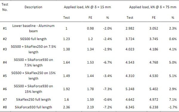
In general, it is evident that the FE results of all samples match well with the test results, with a maximum discrepancy less than 8% for all eight samples. The discrepancies may be due to prototype imperfections and/or incomplete material characterisation used in the FE study.
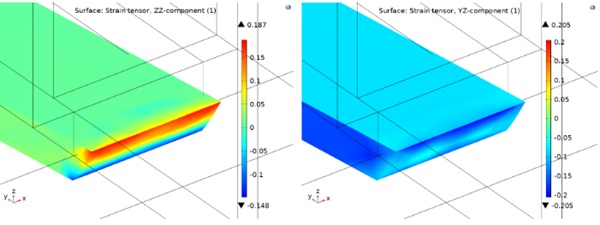
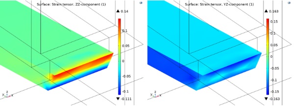
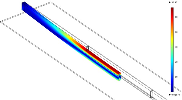
The shear and tensile strains in the structural silicone/adhesive predicted by FE near the beam ends are shown in Fig. 16 and Fig. 17, for samples fully bonded with the two adhesives (SikaFlex250 and SikaForce930) and deformation of 47mm (~L/60), respectively. The results indicate that their maximum strains are about 50% of their max elongations, which define their behaviour within the linear stages of preliminary test results provided by Sika AG. It thus validates the feasibility of the linear elastic model assumptions for the adhesives that are applied in the present FE simulations. Once more detailed material characterizations of the adhesives become available, further studies with hyper elastic material models can be carried out to calibrate the current FE models.
The load-deflection curves for each sample predicted by FE are obtained by parametric sweeping in FE simulation, which are shown in Fig. 18. The overall enhancements of each sample by different adhesives over the lower baseline are well matched with those obtained by the test results (Fig. 2).
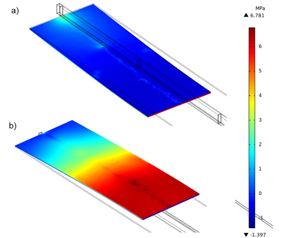
In order to demonstrate that the monitored deflection of span/200 is a true SLS scenario, the stresses in the metal and glass components were studied, see Fig. 19 and Fig. 20. Whilst it was observed that the stresses in all adhesives, i.e. primary silicone sealant and secondary rigid adhesive, were well within acceptable limits, the admissible stresses for the polyurethane adhesives are not fully available at present and the linear models used are not fully accurate. A more detailed study of the behaviour of the two sealants will be presented in an upcoming publication.
4. Directions for upcoming research
The development of the concept for practical applications will need to be based on an interdisciplinary approach and may include the following topics of study:
- A study of the post critical behaviour of the tested samples:
Whilst it has been demonstrated that the aluminium extrusion undergoes plastic deformations and excessive deflection (considered ULS failure), selected samples from the program were tested past failure and to destruction.
The records of these tests are not part of the current scope, but will be analysed and presented in an upcoming publication, to gain a more complete understanding of the full behaviour of members constructed according to the proposed principle.
- A material study regarding the secondary adhesive:
Whilst the secondary adhesives have been demonstrated to effectively contribute towards increasing the flexural stiffness of the units studies, their full material characterization is not available at present.
Furthermore, it is recognized that the performance of the secondary adhesive needs to be studied at elevated and low temperatures, as well as other environmental conditions.
Development of the material(s) in terms of their application and detailing within a façade system is required.
- Development of calculation methods:
It has been demonstrated that members constructed according to the minimal wall principles display consistent behaviour and this can be matched closely by finite element method analyses.
Nevertheless, guidelines will need to be developed for the practical application of the concept in terms of structural analysis.
- Experimental studies on complete units:
Whilst the four point bending tests and the corresponding FEM simulation effectively demonstrate theprinciple, experimental studies of complete units will be required for practical applications. The testing should include short term variable flexural load and temperature variations.
- Study of potential embodied carbon savings:
Whilst it is clear that reductions in metal mass directly result in emissions savings, a more detailed study is required to quantify how the proposed structural optimization translates to embodied carbon emissions savings.
- Code compliance and local construction regulations:
Whilst the proposed principle doesn't contradict any European wide codes of practice or regulations, country specific rules may apply. Further assessment work may be needed to market a product based on the proposed concept.
5. Conclusion
The study carried out demonstrates that partial composite behaviour can be an effective way to structurally optimise the framing members of SSG unitised systems. Such an optimisation can in turn be used to drive down embodied carbon emissions in facades.
It has been demonstrated that conventional SSG bending members have an innate stiffness benefits of approx. 22% when compared to non-composite members. In accordance to the product standard for curtain walling, this can be used in design, subject to appropriate means of calculation.
Furthermore, hybrid partially composite members can have up to 91% improved out of plane stiffness characteristics compared to non-composite members with the same use of materials.
All tests carried out have shown consistent results across a number of samples.
Despite the incomplete material characterisation available for all materials, a good correlation can be achieved between physical tests and numerical simulation, providing the basis for future structural design methodology.
Whilst further inter-disciplinary research is needed for optimal practical applications, the current study has proven that partial composite behaviour in facades is a viable means to optimise material use in facades.
On the basis of this research, and respectively the means of structural optimalization it enables, substantial material savings can be realised without sacrificing overall stiffness and strength. This innovation shall thus be used to significantly reduce the embodied carbon emissions in conventional facades.
Acknowledgements
The authors wish to thank Sika AG, in particular Martina Schwipl, Pedro Galvez and Viviana Nardini, for their fantastic support and invaluable input over the whole course of the study up to date.
Many thanks to all employees of Schüco International KG, in Bielefeld and worldwide, especially the team at the Technology Centre Bielefeld where the tests were conducted as well as Tobias Burchard for his amazing work on the test specimens.
Special thanks to Raya Trifonova and Karl-Stefan Dewald from Schüco International KG for their collaboration and work on the entire minimal wall concept.
References
Alcaine J., L. P. F. E., 2020. Structural Silicone Glazing – Design & Modelling. Ghent, Belis, Bos & Louter.
Anon., 2024. Composite construction. [Online] Available at: https://www.steelconstruction.info/Composite_construction
ASTM, 2016. Standard Practice for Determining Sandwich Beam Flexural and Shear Stiffness. s.l.:s.n.
BS EN 13830, 2015. s.l.:s.n.
CEN, 2005. BS EN 1990:2002+A1:2005 - Eurocode. Basis of structural design. s.l.:s.n.
CEN, 2005. BS EN 1994-1-1:2004 Eurocode 4. Design of composite steel and concrete structures - General rules and rules for buildings. s.l.:British Standards Institution.
D., Z., 1995. An Introduction to Sandwich Structures. s.l.:s.n.
Gargallo M., C. B. G.-S. A., 2021. Material Selection and Characterization for a Novel Frame-Integrated Curtain Wall. Advances in Construction and Building Materials 14, p. 1896.
Laufs W., S. G., 1999. Stress distribution in thermally tempered glass panes near the edges, corners and holes. Part 1. Temperature distributions during the tempering process of glass panes. Glass Science and Technology -Frankfurt am Main- 72, pp. 7-14.
Nations, U., 2015. Paris Agreement. Paris: United Nations.
Nhamoinesu S., O. M. S. V. E. O., 2014. The mechanical performance of adhesively bonded steel-glass composite panels – Medium-scale tests and numerical models. Lausanne, Switzerland, Taylor & Francis Group, London, pp. 269-276.
Nielsen J., O. J. P. P. S. H., 2010. Simulation of residual stresses at holes in tempered glass: A parametric study. Materials and Structures/Materiaux et Constructions, pp. 947-961.
Overend M., N. S. W. J., 2013. Structural performance of bolted connections and adhesively bonded joints in glass structures.Journal of Structural Engineering 139, p. 04013015.
Pascual C., M. J. O. M., 2017. Adhesively-bonded GFRP-glass sandwich components for structurally efficient glazing applications. Composite Structure, pp. 560-573.
Pascual C., N. S. O. M., 2019. The flexural response of large scale steel-framed composite glazing panels. Glass Structures & Engineering 4.
Schittich, et al., 2007. Glass Construction Manual. s.l.:Birkhäuser.
Silvestru V., K. G. B. F. S. J. E. O., 2019. Adhesively bonded glass-metal façade elements with composite structural behaviour under in-plane and out-of-plane loading. Engineering Structures 200.
Thomas, H., Roland, K. & Werner, L., 2018. Facade Construction Manual. s.l.:Birkhäuser.


 demonstrator at Glass Technology Live during Glasstec 2024 (© Cas Maertens).")