This paper was first presented at GPD 2015 by Prof.dr. Mick Eekhout (General director Octatube Delft and Professor of Product Development TU Delft).
Abstract
In the time of my professorship 1991-2015 I have initiated research & development of’ Zappi’ the unbreakable glass structural material. It lead to a number of development in my chair by Fred Veer up to 2005. Other research projects have shifted the borders of possibilities, but without much consequences for practice. Standing with both feet in industry and in academia, the possibility exists to enrich both sides with questions, project proposals and with experiences. In the meantime in practice projects were designed, developed and built that really shifted borders.
A ‘Zappi’ bridge for the Chinese embassy in The Hague; translucent glass fins for the V&A Museum of London; Quattro main and triple secondary glass fins for the Municipal Museum in The Hague with long and heavy loaded glass fins; extremely long glass fins for roof and facades of the Van Gogh museum in Amsterdam; all these projects display glass fins as the main components for load bearing structures in roofs and facades. Their safety behavior after breakage of one plate is reason for practical research as well. The practice loading and destruction tests show that breaking of 1, 2 even 3 blades of a laminated triple fin does not lead to collapse and lethal danger.
1. Introduction: The quest for Zappi 1992 -2015
In 1992, at the start of my professorship on the Chair of Product development at TU Delft, the idea was launched to develop a new stiff, transparent structural material that would be tough, resilient and not prone to sudden breakage, that would greatly deform before yielding. In the idea that this was chemically an improbable material combination, the quest was seen as an improbable ambition, a quest for the holy grail. The name ‘Zappi’ was launched as a marketing tool to attract interest from the industry and government.
Already within 1 year Asahi Glass staff members from Japan visited the TU to inquire how we would have developed with a few staff members what they could not do with 200 researchers. Only in 1995 Fred Veer joined the chair part-time. Immediately he pronounced the requested properties as an impossible combination. So after this chemical abortion not much is to be reported in this respect. But the quest was set in and every new idea of architectural design, structural design, glass design was seen in the light of an improbable row of incremental innovations in order to innovate the design possibilities of engineering with glass.
2. Safety behavior of laminated glass fins
For years and years research, development and discussions have been made on the safety of glass structures. The safety of glass panels is overviewable and came to an end when monolithic glass was substituted by laminated glass, with the requirement that individual glass panels would be strong enough to resist the man loads for overhead glazing and would not shatter; always stay in place. Which is better done with heat-strengthened glass than fully tempered glass.
But the axiom is that overhead glass panels can break but always have to stay in place and should be able to carry the live load of 2 men: one engineer and one Red-Crosser. The safety of glass beams is completely another matter. When a glass beam of glass fin shout break and collapse, it would initiate a consequence of yielding glass panels. So the requirement for a glass beam as a trustworthy structural member is to say in place and to continue to support the glass panels.
2.1 Swiss Life abortion
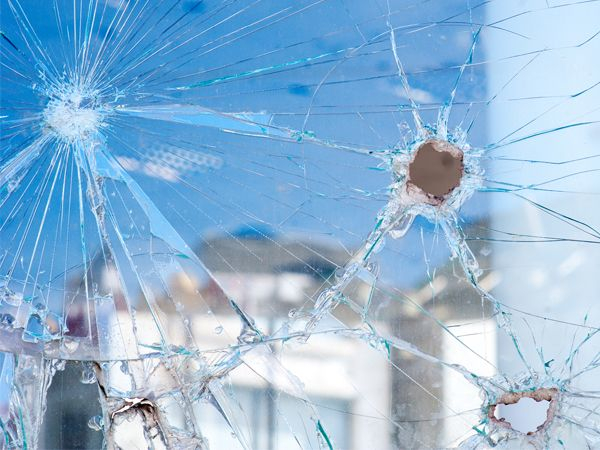
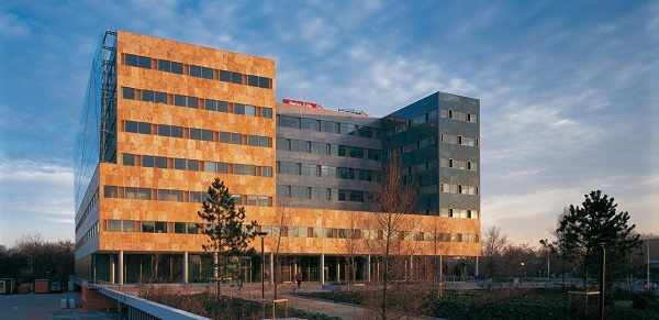
During the project of Swiss Life / Zwitserleven in Amstelveen, NL, where a 27 m long glass beam was designed of triple laminated annealed glass panels, knotted together with steel connectors on a free height of 25 m right above the main entrance of this insurance company, tests were done with the breaking of glass panels on 25 m height. A single fully tempered glass panel was broken and shattered in pieces, but also in large fragments that, when falling from these heights, can be lethal.
A laminated and fully tempered glass panel was broken and sailed like an autumn leaf sideward and downward. When it would have been a façade panel, it would have shattered a number of lower vertical panels, before landing on or in the ground. The lesson learned was: the glass panels have to be kept in its position, falling down had to be prevented by all means. In the designed 27 m long glass beam breaking out of one panel would lead in the complete collapse of the glass beam.
My initial counterproposal was to introduce two hanging cables of 27 m span, in between the glass panels would be connected. In that case the glass beam would not have been a glass, but unwanted by the original designers.
At the end of 3 years of development the experimentation was stopped, we had invested 90% of the project budget to laboratory work and testing, without a satisfactorily result, nor with any budget to realize the original dream of the architect and structural designer. But the project was stopped just before we started to test load a 1 to 2 scaled glass beam.
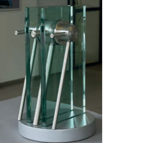
The conclusion of this aborted glass project was: never make a glass beam structure with a free span without a proper second load bearing route. The solution of a metal weave, embedded in a double PBB film between the 3 glass panels, the glass panels in fully tempered glass and glued connections would have been possible, but the nodal test under the allowed conditions did not bring us near to the required glass safety factor of 4. Only 8 years later graduation student Fokke van Gijn would solve the problem with the high connection forces by a large glued connector, which has been patented.
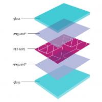
This experience is introduced in this contribution on glass fins as glass fins have the same requirement: never a glass fin is allowed to yield as it will be followed by a progressive collapse of more glass panels, which is dangerous and lethal for users of the building. So the requirement for the glass fin is to stay in position, broken or not. The lamination is advised to be a triple lamination, so that both side glass panes could be broken and the middle one still remains active.
3. Recent projects with large fins
The possibility to produce larger fins by new tempering ovens and lamination ovens Initiated in the zero years the possibility to make glass structures with glass funs as the major structural beams. The first generation were single solid glass beams in float glass, and a bit later in fully tempered glass. In facades these fins were quite vulnerable for damages. When fins grew larger initially they were made of annealed glass. After the initial investments of Seele and NorthGlass to produce for Apple stores larger fins, production possibilities grew.
The Seele fins are perfectly made, but expensive. The NorthGlass fins require an engineer to supervise the project production in order to assure the proper quality. And there is the question of shipment and transport over a long distance and with 4 weeks of time from China overseas to Europe. In the mean time glass fins are made in triple laminations: on either side a glass pane can be damaged and inactive and still the central one has to function. Anyway, fins of different and larger lengths are possible.
3.1 Victoria & Albert museum
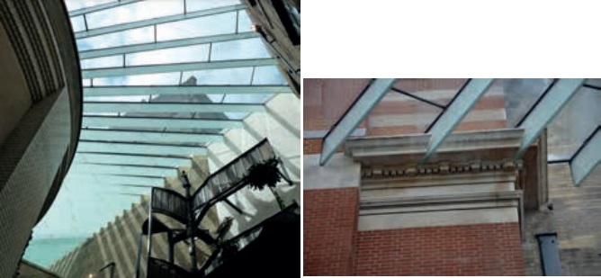
First major project with fins of different lengths and angles in the roof was for the Victoria & Albert Museum in London, arch. Muma, engineer Tim Mc Farlane, where insulated and laminated glass panels were forces in warped form in the fins. For that purpose the fins got a stainless steel top profile so that local tensions form twisting the roof panels would be distributed more evenly on the glass fins. The translucent PVB film in the laminated beams resulted in an astonishing beauty from the beams as wings.
3.2 NAi, Rotterdam
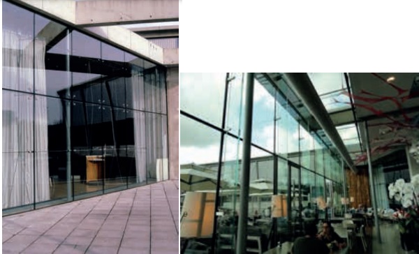
The lobby level of the Netherlands Architecture Institute in Rotterdam, arch. Jo Coenen, 1995, was engineered and built in tension trusses and double glass panels with half mechanical, half chemical Quattro connections. The glass part was the result of a specific and subsidized experiment. The recent extension, again designed by the office of Jo Coenen and engineered and realized by Octatube, substituted the tensile trusses by glass fins. In doing so the change-over from technical care and detailing to abstract design is visible.
3.3 Municipal museum
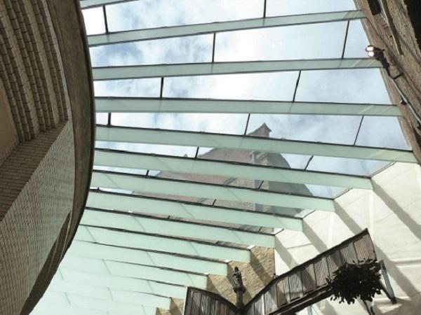
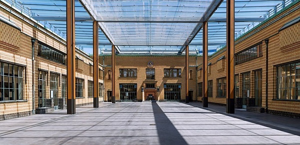
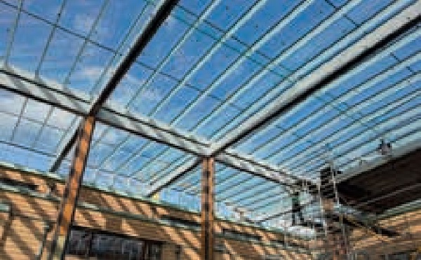
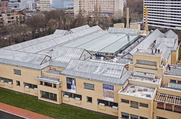
In the 20x40m2 large atrium covering of the Municipal Museum of The Hague, arch. Job Roos, 2014, triple laminated low iron glass fins were employed as the whitish secondary beams, for the perspective effect of open straight above the spectator and closed seen tangentially (at the end of the atrium). These fins have a stainless steel connector on top, fully silicone glazed to connect fin and the insulated, laminated roof panels in low iron glass. In the center of the atrium primary quadruple laminated glass beams were used, also in low iron glass, spanning 13 m with a structural width of 10m (in the secondary fins), so heavy loaded glass fins. In counter light the main fins in low iron are almost invisible.
The roof has been designed to almost disappear visually, leaving the metal columns and beams as a tribute to the original architect Hendrik Berlage (1856-1934). The side columns supporting the outer areas of the roof and the facades are made as glass fins in low iron and are hence also almost invisible. They are triple laminated glass studs of 200 x 30mm. They make the roof edge fly like an extended wing.
3.4 Van Gogh
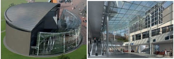
For the Van Gogh museum extension in Amsterdam, arch. Kisho Kurokawa, Hans van Heeswijk, 2015, similar triple laminated glass fins were employed, but this time completely transparent, in low iron glass, spanning between tubular steel edge profiles that act as the bending/compression elements of the roof. The specific form of the roof makes it free form technology which resulted in complicated shoes welded on the CHS members to connect the glass fins for the roof and for the façade. The roof fins are covered by laminated insulated flat and warped glass panels. The facades are formed by cold bent insulated façade panels, forced from their flat form into in a curved form by an electrical robot embrace.
4. Final long lasting bending test of laminated glass fin
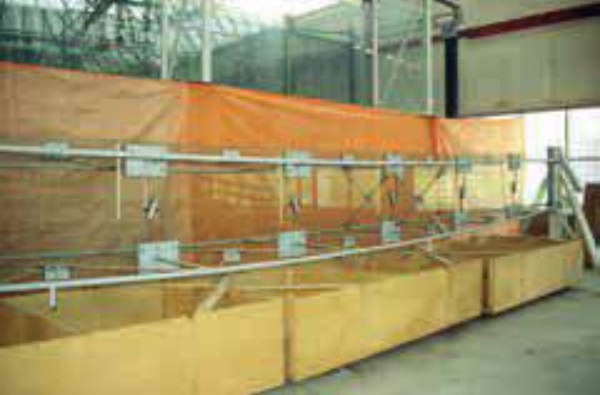
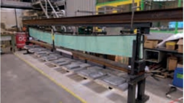
What is the residual strength of a completely broken glass fin? For that purpose a test was done in the Octatube laboratory. A triple laminated fully tempered 7 m long glass fin as used for the Gemeentemuseum / Municipal Museum in The Hague was set up in a mock up with loadings equivalent to the dead weights of the roof plane (glass panels on to of the fin) plus live loading on the roof of a glass fin spaced @ 2m distance. The upper detail contained the stainless steel RHS profile, fully sealed with silicone on top of the fin, on which the glass panels would be placed with rubber of silicone and the occasional clamp to prevent uplift.
The first glass pane of the beam was broken, no deformation. The second one was broken, also without any deformation. Because of the fully tempered character breaking occurred in the usual small fragments of around 10 mm3, held together buy the PVB film. After that the middle pane was deliberately broken en gradually a small deformation sag was introduced over the length of the glass fin. This fully loaded and deformed situation without yielding remained for 4 weeks. Normally this time is long enough to attach a brace and / or to replace the broken fin. A brace would be a lower steel profile, triangulated diagonals upward and connections sideward through the upper stainless steel RHS profile between glass fin and roof panel.
For me this was the end of my adventure of ‘Zappi’. It had resulted in a trustworthy glass structure, reliable enough to build a roof structure with it. Others may continue the quest, their quest. A few months before the retirement date as a professor of product development, I would like to announce my quest for Zappi as completed.
4.1 The end of the quest for Zappi?
What is the lesson of ‘The Quest for Zappi’? The quest for Zappi is eternal. For me this was the end of my adventure of ‘Zappi’. It had resulted in a trustworthy glass structure, reliable enough to build a roof structure with it. Others may continue the quest, their quest. A few months before the retirement date as a professor of product development, I would like to announce my quest for Zappi as completed. Zappi stands for an improbable ambition, that each designer should have to strive at. It functioned in l my professional life and I would which all my engineering colleagues to take up a similar ambition, their own ambition. So I would proclaim: ‘Zappi is found, long live Zappi’. Zappi is forever!
5. Conclusion
The quest for Zappi as announced in 1992 has resulted in another view of safety: not in material level, but at the level of structural design and details. A number of experimental projects with incremental innovations has resulted in safe glass structures for overhead glazing, both in glass planes as in the employment of glass beams of glass fins. Extreme loadings tests in the Octatube laboratory has resulted in a reliable glass fin construction.


