Article Information
- Digital Object Identifier (DOI): 10.47982/cgc.9.472
- Published by Challenging Glass, on behalf of the author(s), at Stichting OpenAccess.
- Published as part of the peer-reviewed Challenging Glass Conference Proceedings, Volume 9, June 2024, 10.47982/cgc.9
- Editors: Christian Louter, Freek Bos & Jan Belis
- This work is licensed under a Creative Commons Attribution 4.0 International (CC BY 4.0) license.
- Copyright © 2024 with the author(s)
Authors:
- Minxi Bao - Eckersley O'Callaghan
- Kevin Yin - Eckersley O'Callaghan
- Wei Li - Tianjing North Glass

Abstract
Increasing trends and demands for curvilinear glass forms in the architectural, automotive and marine industries have inspired the research and development of alternative glass bending methods. Warm bent lamination, also known as cold bent lamination, has emerged as a promising method for introducing curvature in laminated glass. Research on warm bent glass to date has mostly focused on the initial spring-back effect after the removal of the temporary mechanical supports and the long-term relaxation action over time. However, studies on the post fracture performance of warm bent laminated glass are scarce. The high bending stiffness of laminated glass introduced though the induced curvature is highly beneficial in structural glass applications, however, this could be compromised by the spring-back effect following fracture and could eventually trigger ultimate limit state limitations until their safe replacement. This paper experimentally investigates the post-fracture performance of warm bent laminated glass. A number of parameters are tested, taking into account the different laminate layouts, glass geometries and types. The laminated configurations are fracturedin a controlled manner and the post-fracture spring-back are identified. These findings can provide useful insights for the post-fracture mechanical response of warm bent laminated glass, point out important considerations for future design and promote the safe use of warm bent laminated glass in load bearing applications.
1.Introduction
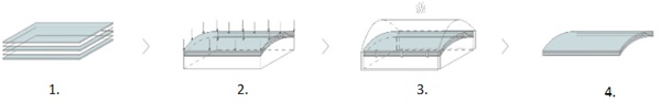
The increasing interest in curvilinear forms for the architectural and marine industries has pushed the development of alternative, cost effective and energy efficient bending methods. Warm bent, alsotermed as cold lamination bending has emerged within the last decade, offering a cost and energy efficient alternative to hot bending. The process comprises the following steps:
- Unbonded sheets of glass and interlayer sheet(s) are prepared.
- The assembly is bent in the desired shape and held in place with external mechanical fixings.
- The curved unit is subsequently laminated in an autoclave.
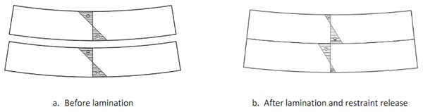
- Following lamination, the unit slowly cools down to ambient temperature and the mechanical restraints are removed. After the spontaneous spring back, the curved shape is partially maintained through the shear coupling action of the interlayer.
Warm bent offers a joint advantage as it provides a bending solution minimising energy consumptionand optical distortions. The lamination is performed at temperatures significantly lower than the glass transition temperature (Tlam=140oC, Haldimann et al, 2008 vs Tg≃610oC for hot bending soda lime silica glass) which needs to be exceeded during hot bending for the glass to sag under its self-weight and obtain the desired geometry of the mould. Furthermore, it minimises the need for permanent mechanical restrains that are required to retain curvature in site cold bent glass. Warm bent is obviously limited to laminated glass. However, this does not pose a limitation as laminated glass is predominantly used in structural glass applications. Apart from avoiding injury by retaining the fragments in case of fracture, laminated glass also provides post fracture load capacity and allows its safe replacement by partially maintaining its stiffness as the fragments interlock with one another.
However, warm bent glass is subject to partial instantaneous spring-back after the removal of the temporary supports and long-term relaxation due to the viscoelastic, time and temperature dependent properties of the interlayer. These phenomena not only cause time dependent changes in the glass geometry during its service life but also lead to stress redistribution. Therefore, the rheological response of the interlayer needs to be predicted and considered during design. An analytical prediction model is available for this in Galuppi and Royer-Carfagni, 2015. Galuppi and Royer-Carfagni, 2014 also showed that the instantaneous release of the temporary supports used during lamination leads to the development of significant shear stress in the interlayer which can even cause delamination, stressing the need for gradual release from the mechanical supports. The type of interlayer is also important in warm bent. Stiff interlayers, e.g. ionomers, limit instantaneous spring-back and long-term effects during the lifetime of warm bent glass. Soft interlayers, e.g. PVB, however, lead to significant deformation not only after lamination but also during the first few months of their lifetime leading up to 50% of loss in shape (Fildhuth et al., 2014). Such findings can provide useful insights for transport and installation timeframes of warm bent glass but also point out whether locking of warm bent glass in place is required during installation.
Apart from aesthetics and architectural intent, introducing curvature in thin plates additionally increases the glass panel’s stiffness compared to its flat alternative. This is highly desirable for structural glass applications and can be used in favour of slenderness during design. However, the curved geometry is formed by bending a flat glass and this will generate corresponding tensile stress on the glass surfaces permanently. Consequently, the maximum bending stress to accommodate the environmental is reduced. This is to say, with the same level of curvature and external loading magnitude, warm bent laminated glass is more susceptible to bending fracture compared to typical hot bent glass. When warm bent glass fractures post-failure instantaneous spring back is expected to some extent. This leads to an associated reduction in stiffness and therefore, safety could be compromised before the fractured panel is replaced. Nonetheless, this phenomenon has not been investigated to date to the best of the authors’ knowledge.
This paper investigates the post-fracture spring-back effect and the post fracture behaviour in warm bent glass, aiming to assess its safe use in structural glass applications. A group of geometrical parameters including panel dimensions, radius of curvature and bow, and material-related parameters including glass type, interlayer type and laminate build-up are tested individually as influencing factors.
Section 2 below describes the experimental approach. Results and conclusions are finally shown in Sections 3 and 4 respectively.
2. Experimental Method
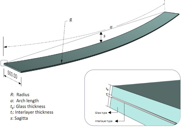
To experimentally investigate the influence of materials and geometry on post-fracture spring-back in warm bent laminated glass, a list of parameters that may exert significant impacts to the spring-back behaviour shall be first identified as illustrated in Fig. 2. Parameters involve panel length, radius of curvature, glass thickness, interlayer type and interlayer thickness. Because the panels are cylindrically bent, i.e. consistent curvature along the length direction, the width of the panel are not varied but considered as a fixed value in this study.
Giving that the radius of the curved panel is not straightforward to measure, the sagitta of each specimen is measured instead. The resultant radius can be calculated through the set arc length and the measured sagitta by following Equation 1.
![]()
where R is radius, a is arc length, s is sagitta. It is worth noting that this equation is a good approximation when R>> s, otherwise more accurate expression should be used. In this experimental study, the curvature is relatively mild since the initial R is already greater than 150 times of s, therefore Equation 1 is accurate enough to calculate the radius of the panel after fracture induced spring back.
The glass specimens were manufactured, laminated and warm bent laminated at the facilities of TianjinNorth Glass Factory in China. The composition of the glass was soda lime silica, and the edges were polished. All panels were warm bent in cylindrical shapes. The glass was heat strengthened or toughened to permit warm bent; the nominal surface compression stress is between 24MPa to 52MPa for heat strengthened (HS) glass, and not less than 69MPa for fully toughened (FT) glass according to ASTM C1048-18.
2.1. Specimens
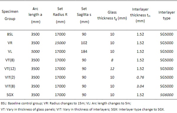
In total, 25 glass panels are manufactured. For each parameter, three identical panels are fabricated and tested. The control group consists of three laminated glass unit with dimensions of 3500x500mm and the following build-up of two pieces of 10mm heat strengthened glass laminated with 1.52mm thick SG5000 interlayer. Table 1 below provides an overview of all the manufactured specimens and their geometry. One parameter (highlighted in italic textin Table 1) is modified each time compared to the control group to enable accurate monitoring of the influence of each parameter on the spring back due to post-failure damage.
Table 1: Overview of Glass Specimens.
2.2. Manufacturing
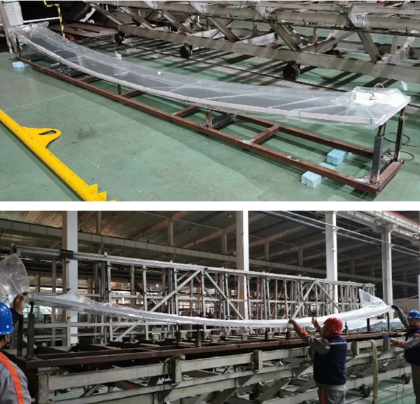
The components of each laminate are placed horizontally in a layered configuration in a vacuum bag. The unbonded unit is laid flat on a steel rig. This comprises adjustable steel posts at the two ends that can be lifted / lowered to force the glass in the desired shape as shown in Fig. 3. The curved unit is subsequently laminated in an autoclave at (140oC) and the temporary supports are gradually removed. The initial bow presented in Table 1 corresponds to the value measured following initial spring back after the removal of the glass from the temporary supports.
2.3. Testing Apparatus
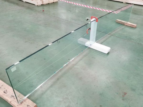
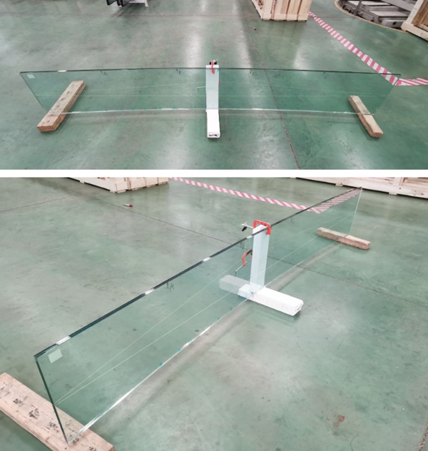
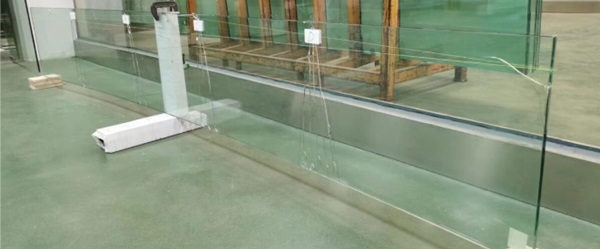
The testing specimens are amounted to a customised supporting rig, as shown in Fig. 4. The specimens are vertically supported at the mid-point of the bottom edge. The rig is lapped around with PTFE tapes providing a smooth contact surface with glass to minimise the friction which could restrain the glass panel from springing back. The two ends of the glass specimens are not supported and free to move in all directions, although two timber blocks are placed below in case the specimen tilts and hits the ground. In out-of-plane direction, a point clamp is employed at the mid-point of the glass top edge to prevent the panel from toppling over while exert minimal impact on the spring-back action.
A pre-tensioned string is tied at the mid-height position of the specimens, to facilitate the measurement of the sagitta.
2.4. Testing procedures
The fracture breakage tests were performed in the following steps.
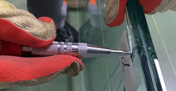
1.Mark up the points to be fractured.
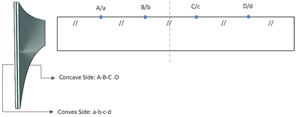
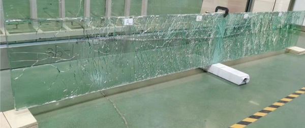
To investigate the relationship between the spring-back extent and the level of fracture, the glass specimens are manually damaged point by point. All the knock points are marked up as shown below in Fig. 5. The points are distributed along the top edge of the glass specimen at equal distance.
2. Break the glass specimens.
The test specimens were manually broken by means of a 6 mm round head center punch along the long edges of glass at 4 points that are equally spaced. The glass ply on concave side was broken at each point prior to breaking the glass ply on convex side.
3. Measure the sagitta with a controlled time gap.
There will be an instantaneous spring back right after the damage occurred. The crack may further propagate over a short period of time and hence result in further spring back before breaking the next point. To capture the latter scenario, the sagitta measurement sequence is proposed as follows:
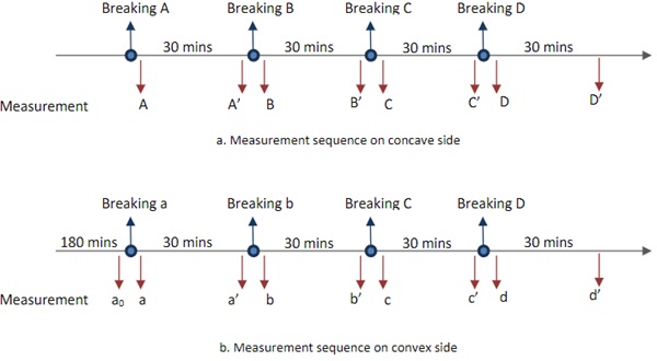
Once the concave side ply was broken at all 4 points, the specimen was left resting for 3 hours before breaking the convex side glass in the same manner. 3 no. specimens for each panel configuration were tested. The average spring back, which is measured as reduction of sagitta were calculated for each specimen set.
3. Results
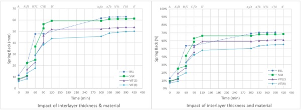
The calculated average spring back at each measurement sequence point as described are summarized in the charts presented in this section. The spring back measurements are linked with straight lines the figures to assist reading the experiment data and do not represent a linear relationship between spring back and time. The vertical linking lines displayed in the figures indicate instantaneous spring back upon breaking glass.
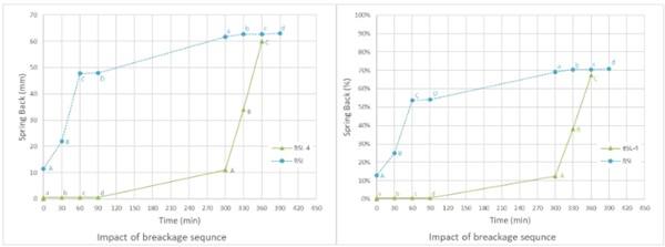
Specimen set BSL is used as the benchmark to evaluate the impact of variations to panel configurations.3 no. glass specimens are teste with glass on concave side broken prior to breaking the convex side.That is in breaking sequentially at points A, B, C, and D first, then at points a, b, c and d. A 4th specimen(BLS-4) was prepared and broken on the convex side first, i.e. at point a, b, c, and d first. It should be noted that, for specimen set BSL and BSL-4 , only the instantaneous spring backs are measured. Thetime delayed spring back 30 minutes after breaking at each points, i.e. measurement A’ to D’ and a’ to d’, are not captured in this experiment and not plotted in the charts in this section.
It can be observed in the experiment that the majority of spring back occurs when the glass ply on concave side is broken regardless of the sequence of breakage. Due to warm bent process, the glass ply on concave side is subjected to additional tensile stress. Upon breaking the glass can no longer sustain the tension, and stress is shifted to the interlayer which has lower stiffness. On the contrary, when breaking the glass ply on convex side, which is subjected to additional compressive stress after warm bent process, the spring back is much less significant as the broken glass can continue carry the compressive stress. Fig. 8 shows the comparison of spring back value and spring back ratio of the average of the first 3 no. specimens and the 4th one. The spring back ration is calculated as the ratio of residual and initial sagitta.
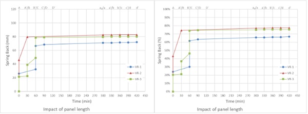
Specimen set VL aims to evaluate the impact of panel length while the other parameters remain the same. The length of specimens is increased to 5m compared to the 3.5m length of the BSL set. The radius of the specimen set VR is reduced to 15m from 17m for BSL set.
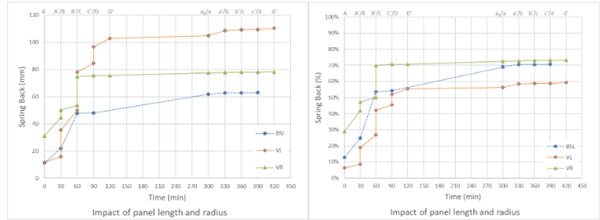
The spring back ratio for set VL is noticeably reduced compared to set BLS. With the radius of specimen set VR reduced, the final spring back ratio increases slightly but the sequence of the spring back occurrence is different.
For specimen set VR, the fracture propagation behaviour varies between individual specimens. A closer study of the measured spring back is shown in Fig. 10. The crack propagated through half of the glass panel when specimen VR-1 is broken at point A. Further spring back occurred in the following 60 minutes. This can be observed through the increased spring back at measurement sequence point B’/C in Fig. 10 . Similar phenomena occurred when the glass was broken at point C with crack propagated through the remaining panel. Specimen VR-2 showed instantaneous crack propagation through half of the glass panel when breaking at point A. The crack propagated to the other half of the glass approximately 4 minutes after initial breakage. The 3rd specimen VR-3 showed minor crack propagation after breaking at point A, but the extent is limited within the location area of the damage point. Instantaneous crack propagation throughout the entire glass occurred when the glass is broken at point B.
The fragmentation of set BLS is observed to be between the typical breakage of flat heat strengthened glass and the toughened glass with small fragments but not as fine as that would be observed in toughened glass. This demonstrates the additional stress locked in the glass due to bending. The fracture pattern of set VL is similar to that of set BLS. Specimens in set VR showed different behaviour upon breaking although the final fracture pattern is similar to set BLS. When the specimens were broken at point A, 1 out of 3 specimens showed instantaneous crack propagation within half of the glass panel. The crack propagated to the other half of the glass approximately 4 minutes after initial breakage. Another specimen within the set did not show the crack propagation outside of the area local to the damage point A. When the glass is broken at point B, it showed similar delay crack propagation as the first specimen. The 3rd specimen within the set showed minor crack propagation after breaking at point A, but the extent is limited within the location area of the damage point. Instantaneous crack propagation throughout the entire glass occurred when the glass is broken at point B.
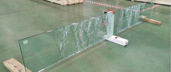
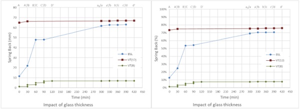
Fig. 12 shows the spring back when the glass thickness varies from the baseline specimen set. The spring back ratio is increased slightly when the glass thickness is increased. Although the difference in total spring back is not significant, most of the spring back of specimens with 12mm thick glass occurred when the glass was broken at the first breaking point and cracks propagated instantaneously. It was observed that the cracks extended further in the area at the end of glass.
For specimen set VT(8) with 8mm glass, the spring back is less than 10% of the initial sagitta. Fracture pattern is similar to the flat heat strengthened glass. Cracks are limited local to the breaking points. This indicates a low level of stress locked in during the bending process.
3 specimen sets with varied interlayer thickness and material were tested to evaluate the impact on spring back ratio and fracturing behaviour. Specimen set VIT(2) comprises 0.76mm thick SentryGlasinterlayer whilst VIT(8) features a 3.04mm thick interlayer. The test results are compared to the BLS set, which were made with 1.52mm thick SentryGlas interlayer. A further set SGX is made with 1.52mm thick SentryGlas Xtra interlayer. The spring back ratios of specimens with both thinner and thicker interlayer are lower than that of the baseline set BLS. The reduced spring back ratio of thicker interlayer may be understood as the interlay would be able to sustain higher tensile stress when the glass on concave side fractures. The reduced spring back ratio with thinner interlayer may be associated with the lower effective thickness, hence stiffness, of the laminated glass. However, this may be balanced out by the lower capability of the thinner interlayer sustaining the tensile stress. Further study and experiment would be needed to evaluate the phenomena in detail.
For set SGX, the average spring back ratio is within 3% of the baseline set BLS. The difference of shear modulus between SentryGlas and SentryGlas Xtra had little effect on the spring back behaviour.
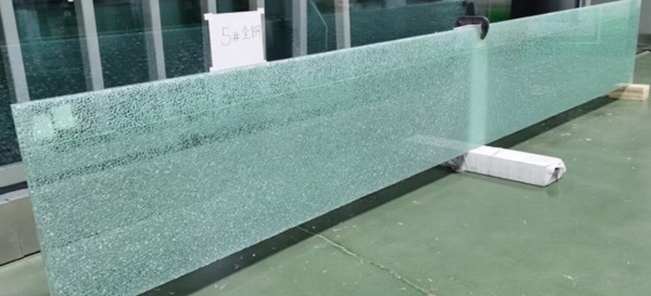
In addition to the specimens listed in Table 1, a glass panel made of fully toughened glass was also tested. The other parameters of the specimen are the same as BLS set. The specimen was broken on the concave side at the midpoint of the longer edger. Upon breaking the glass sprang back reducing the sagitta to 10mm from the initial 90.5mm. The glass continued relaxing reducing the sagitta to 8.5mm after 30 minutes. Fig. 15 shows the fracture pattern of the glass.
4. Discussion
Bending stress field is induced on both plies of the laminated glass when glass is forced to curved shape prior to lamination. Following lamination and release of the temporary support, additional tensile stress develops in the glass on concaved side and compressive stress in the glass on convex side due to the shear coupling of the interlayer. The change of stress in the glass at the two different stages are indicated in Fig. 17.
Different post failure spring back behaviours corresponding to different breaking sequencesdemonstrates the change of stress distribution in warm bent glass.
Permanent stress and strain energy are locked in the glass through warm bent process. As such, the fractured fragmentation is finer than typical pattern observed in flat glass.
The thickness of glass not only affect the post fracture spring back ratio, but also the fracture pattern. The specimens with 10mm and 12mm thick glass showed similar final spring back ratio though the spring back occurred instantaneously when the glass was broken at the first point for 12mm thick glass.
The radius of the glass has similar impact on the post fracture behaviour. Both increasing glass thickness and reducing radius increase the locked-in stress and energy, which lead to the glass behaves closer toughened glass. This is demonstrated through experiment in this study.
The experiment also demonstrates that the crack may propagate to extended area from the damage point, or even through the entire glass pane. The cracks propagated through the entire glass pane upon damage for specimens with 12mm thick glass. Similar crack propagation is observed in the glass with reduced radius. Two of the specimens with reduce radius showed a delayed crack propagation. This reflects the time dependent behaviour of laminated glass due to the viscosity of interlayer. The impact of length of glass panel on post fracture behaviour is not significant for glass penal with constant radius.
Interlayer provide the shear coupling between two plies of glass. This enables the glass laminate to maintain curved geometry when released from the support. The interlayer thickness affects the post fracture spring back. When the glass under tension, i.e. concave side glass, is broken, the tensile stress in the glass is shifted to the interlayer. Within the specimen configurations tested in this study, the configurations with both thicker and thinner interlay displayed reduced post fracture spring back.
5. Conclusion
This study explored the post-failure behaviour of warm bent laminated glass by measuring the spring-back amount during a controlled glass breakage process. We examined the impact of various geometry and material parameters on the post-failure behaviour of the glass.
For heat-strengthened glass, the spring-back magnitude was found to correlate with two factors: 1) the breakage of different ply, and 2) fracture fragmentation. Breakage of the concave panel caused significant spring-back, whereas breakage of the convex panel only slightly affected the overall curvature. This difference arises because the redistribution of strain energy within the laminate assembly leads to an unequal tension compression coupling on the surfaces of each glass ply. The stress magnitude on the surfaces interfacing with the interlayer is higher than on the free surfaces.
Additionally, the higher lock-in strain energy within the assembly alters the fracture fragmentation patterns. Fracture patterns in heat-strengthened warm-bent laminated glass were generally observed to be finer than those in flat heat-strengthened laminated glass. The finer the fracture pattern, the higher the lock-in strain energy and consequently, the greater the spring-back, which also indicates a lower residual structural stiffness.
Reviewing experimental results revealed that the fracture fragmentation density is influenced by factors such as the thickness of the glass and the bending radius. Thicker glass and tighter radii lead to higher locked-in stress, resulting in smaller post-f racture fragments. When the locked-in stress and strain energy are sufficiently high, cracks propagate to a wider area of the glass or, in extreme cases, throughout the entire glass pane. Further studies are required to understand the threshold above which cracks propagate beyond the area local to the impact point.
Glass structures often benefit from the increased rigidity of curved glass. However, post-fracture spring-back reduces this rigidity if the glass is not adequately restrained along the curved edges. The potential of spring back also put additional stress in structural silicone for frameless systems, hence may increase the risks of bonding failure. This study investigated the post-failure fracture and spring-back behaviour through experimentation. Future research on predicting spring-back could enhance the post-fracture design of warm bent glass and supporting mechanism.
References
Haldimann, M., Luible A., Overend, M., Structural Use of Glass, Zurich (2008)
Galuppi, L., Royer-Carfagni, G., Localized contacts, stress concentrations and transient states in bent-lamination with viscoelastic adhesion. An analytical study, Int. J. Mech. Sci., vol. 103, 275-287, (2015)
Galuppi, L., Royer-Carfagni, G., Rheology of cold-lamination-bending for curved glazing, Eng. Struct., vol. 61, 140-152 (2014)
Fildhuth, T., Knippers, J., Bindji-Odzili, F., Baldassini, N., Pennetier, S., Recovery Behaviour of Laminated Cold Bent Glass: Numerical Analysis and Testing, Challenging Glass & COST Action TU0905 Conference (2014).