This paper was first presented at GPD 2019 by Eric Wang, Ming Yu, Valerie Hayez and May Jiang¹ from Dow Silicones.
Since structural silicone glazing (SSG) was introduced to China in 1980s, it has been widely used in glass façades of high-rise buildings. South China, a rapidly developing economical, is home to an increased number of new skyscraper projects, while it also experiences the highest frequency of typhoons in China. As climate change enhances the frequency and strength of typhoons these extreme climatic conditions bring both challenges and opportunities to structural silicone glazing application, which needs to achieve a balance between vision aesthetics and strength requirements.
This case study describes the façade performance of the 2nd tallest building in China, the Ping An International Finance Center (Ping An IFC), located in the city of Shenzhen. It is currently the tallest building with a 4-sided structural glazed unitized stainless steel façade in the world. The building is in a high frequency typhoon zone with associated high wind loading. FEA modeling and extensive testing were used to ensure the SSG design would be able to accommodate the high movements due to the extreme wind load while ensuring excellent long-term adhesion. In 2018, the IFC façade experienced successfully the super typhoon Mangkhut, the strongest typhoon in the last 35 years, with wind speeds reaching 47.8m/s.
Introduction
Silicone construction sealants were introduced in the early 1960s [1] and the structural silicone glazing (SSG) attachment method of glass panels has been used for nearly 50 years as an enabler of better building aesthetics and performance [2]. SSG use has become ubiquitous in the world of enclosure design and construction and as such is well recognized by many building designers for offering high degrees of design freedom through its capacity to transform the exterior aesthetics of the façade by making vertical framing components disappear while providing load transferring capability and enhance uncontrolled air and water penetration resistance.
The SSG façade of today, not only provides appealing aesthetics to the building, but also fulfils a capacity to protect the building from daily environmental conditions, such as rain, UV and wind. Structural silicone provides a continuous thermal, air, and water barrier when it is fully applied on all four sides of the glass and bonded to the supporting framing system.
The silicone rubber anchor also absorbs seismic and interstory drift movements that happen in a curtainwall. When relevant for the geographic project location, additional requirements of performance can be needed to be able to withstand extreme windload conditions observed during typhoons or hurricanes. Both are tropical cyclones and only differ in the location where they occur. In the North Atlantic, central North Pacific, and eastern North Pacific, the term hurricane is used. The same type of disturbance in the Northwest Pacific is called a typhoon.
Meanwhile, in the South Pacific and Indian Ocean, the generic term tropical cyclone is used, regardless of the strength of the wind associated with the weather system [3]. Typhoons typically form and make landfall in the Pacific/South China Sea region from the months of July to September, which accounts for an average time of 76% of the total formations in a typical year [4, 5].
Environmental scientist of the University of California in San Diego, Prof. Shangping Xie said, increased sea temperature levels will intensify the strength of these storms. In the summer of 2018, many areas reported abnormally warmer sea water temperatures; more evidence that global warming is an inevitable trend on the Earth. A study published in ‘Nature-Earth’ confirmed this statement that since 1977, typhoon strength increased 12-15% in the Pacific Northwest area [3, 6], including Northern South China Sea and Taiwan Strait.
Statistically, the coastal region of South China experiences the most frequent typhoon events, accounting for 60% of the total area for the whole year. The major influenced cities or areas include Taiwan, Fujian, Guangdong, Hainan, Zhejiang, Guangxi. According to the research results of the typhoon impact on Asia-Pacific region, China has the tallest buildings – both existing and under construction - and has observed the highest annual economic loss because of typhoon activity, damage, and related disruptions. [4, 7]
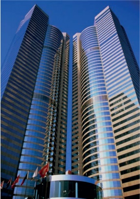
SSG was introduced to mainland China in 1980s and its use spread rapidly with the growth in the design and construction of high-rise buildings and façades throughout the whole country, especially in economically fast-growing areas, like East China and South China which include the cities of Shenzhen, Guangzhou and Hong Kong. One of the first SSG projects in Hong Kong is Exchange Square, constructed in 1984.
These 200m high towers comprise two-sided structurally glazed facades using DOWSIL ™ 795 Silicone Building Sealant. The monolithic glass is 1600 x 1280mm and was bonded with a 40mm structural sealant bite to resist a design windload of 5.1kPa. This structure has withstood the test of time and more than 100 typhoons since its construction in the 80’s, including the recent passage of Typhoon Mangkhut in October 2018 whereby the highest recorded wind speed reached 290 km/h (180mph).
The repeated and time tested functionality of the silicone application on this building, and others from the same area, are a testimonial to the proven performance of structural silicone and the design and installation requirements stipulated and implemented by the value-chain; including but not limited to: procedures in Dow’s Technical Manual, materials Standards such as ETAG002, the ASTM C1401 or the GB 1776, Project Specifications, and local jurisdictional requirements. [8, 9, 10]
However, the higher frequency and strength of typhoons lead to increased windloads imposed on the SSG, and consequently according to the above-mentioned standards, increased joint dimensions which are often inconsistent with the desired (aesthetically) thin profile systems. For those cases where one deviates from the recommended joint dimensions, it becomes necessary to apply advanced calculation methods such as Finite Element Analysis (FEA) to verify the stresses and strains occurring in the joint.
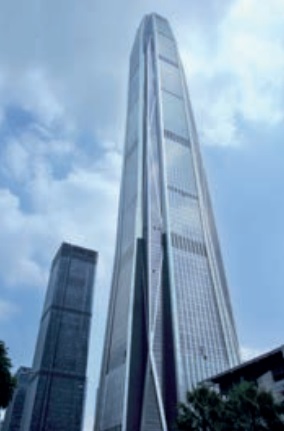
Ping An International Finance Center (Ping An IFC) is a 118-floor, 599 meters high, supertall skyscraper in Shenzhen, by the architectural team of KPF/CCDI. The building was completed in 2017, becoming the tallest building in Shenzhen, the 2nd tallest building in China and the 4th tallest building in the world. It also shares the distinction (with the Shanghai Tower) of having the highest observation deck within a building at the height of 562m.
The building is located within the Futian District, the Central Business District of Shenzhen. The façade was constructed and structurally glazing conducted by Shenyang Yuanda using DOWSIL™ 993N and 995 Silicone Building Sealants as the structural sealants (respectively to bond glass and stainless steel panel), where the insulating glass was sealed with DOWSIL™ 3362N Silicone Building Sealant as the secondary seal, and DOWSIL™ 791 Silicone Building Sealant for the weathersealing.
This building façade used large size glass units and requires high wind-load design as it is in the coast region of South China. Therefore, under these combined conditions, it must be considered that the building needs to undertake the potential strong and frequent typhoons. The planned profile systems were too thin to be able to accommodate the joint required to withstand the expected windload and hence, a smaller joint was considered.
Joint dimensioning
Structural silicone sealant glazing system has been proven to be a safe system based on several decades application success history, but it still needs emphasis that the constant evolution in façade systems, the meticulous workmanship required, the compatibility concerns, and the need of quality assurance test and process result in varied degrees of reliability [6]. To ensure the safety of the façade structural glazing, a systematic technical support was provided to the Ping An IFC project team.
The support included early communication with building consultant and fabricator on the sealant selection and was followed by a series of laboratory evaluations to recommend sealant application process, based on the sealant/substrates adhesion test and the sealant/accessories compatibility test. A sealant application workshop training was provided before the manufacturing of the façade. An on-site regular façade unit deglazing check was provided along the whole manufacture process of façade project. The whole comprehensive systemic service ensured the safety and accuracy of structural sealant application and consequently provided the expected performance.
The review of proposed structural bite joint design and configuration in the shop drawings was an essential part of the technical support. The project uses 4-sided structural glazing whereby the dead load of all the glasses is permanently supported by mechanical means. The biggest glass panel size is 1500mm X 1700mm.
The 50 and 100 years recurrence windload based on the location in Shenzhen are respectively 750Pa and 900Pa according to the Chinese building code [11]. However, as Shenzhen is in a high-risk area for typhoons, a design windload of 5.72kPa was required. This extreme windload challenges the conventional methods of joint dimensioning, since using joint calculation equations as provided in ASTM C1401 or ETAG002, results for this type of projects in economically unacceptable large bite sizes which are not always compatible with the frame designs.
Indeed, according to standard ASTM C1401, a joint dimension of 32mm by 11mm should be used for a windload of 5.72kPa. However due to the frame design limitation a joint with a lower thickness of only 8mm could be accommodated. The bite was slightly increased to 35mm and a final joint of 35x8mm was proposed. As this differs from the requirement of the standard, Finite Element Analysis (FEA) analysis was performed to ensure the performance under these extreme environmental conditions would maintain the integrity of the building envelope.
Finite Element Analysis (FEA)
For the numerical simulation, the commercial Finite element software code ABAQUS [12] was used to simulate measurable joint deformation because this variable has a lower sensitivity to mesh configuration. Indeed, observable deformation results from the integral of the strain energy over the whole joint volume hence local high stress values which are highly mesh sensitive are averaged. Joint deformation calculated using FEA for one façade can be compared to H-bar testing results for test pieces having the same geometry and more particularly similar joint aspect ratio R (defined as the ratio between joint bite and joint thickness e) [13, 14].
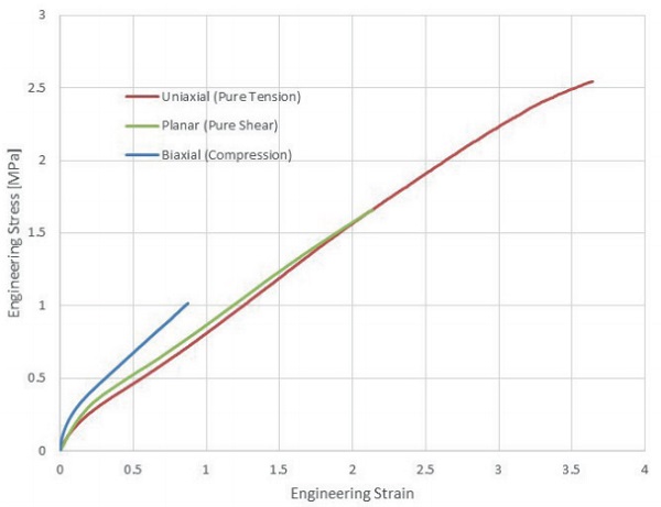
The structural sealant used in the project is the China produced 2-component DOWSIL™ 993N Structural Glazing Sealant. The design stress in tension is 0.14MPa, in dynamic shear 0.11MPa and in static shear 0.011MPa. The material was extensively tested in pure tension shear and compression at Axel test laboratory [15].
The silicone was modeled assuming a hyperelastic and incompressible material law. A polynomial second order A Mooney Rivlin material model provided the best fitting results.

where U is the strain energy per unit of reference volume, Cij and Di are material parameters, I1 and I2 are the first and second deviatoric strain invariants, Jel 2 I is the elastic volume ratio. The utilized material parameters are listed in Table 1.

For cases where the strains are small, the first terms in the polynomial series usually provide a sufficiently accurate model.
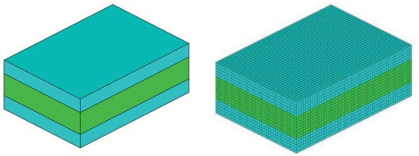
Before conducting FEA on the façade unit, it is necessary to translate the maximum design values (i.e. 0.14MPa design stress in tension) into Finite Element context (corresponding stress or Strain criteria). Therefore, a calibration exercise was performed on a simple H-bar having the same geometry as the joint intended on the façade, i.e. 35x8mm² for a length of 50mm. Substrates should preferably be chosen as steel. This material, as well as its thickness set at 5 mm, will ensure no bending will happen. The linear elastic model with 210 GPa Young’s modulus and 0.3 Poisson ratio were used for stainless steel.
One critical aspect in FEA resolution is the proper mesh setting, which depends on the physics of the problem to be solved [16]. The size of the mesh element should be small compared to the gradient of the variable being evaluated to guarantee that the discretization of the equation leads to a representative image of the physics under study. In an infinitively thin plane close to the surface of adhesion, the silicone cannot reduce its cross section and experiences high stresses which decrease when moving away of the plane of adhesion as cross section reduction is possible. The mesh of 1mm³ rectangular cells (1 mm x 1 mm x 1 mm) was generated for both the sealant and the substrates as illustrated below.
The H-bar modeling studied how the stress and strain distribute on sealant layer when the unit undertakes a nominal tensile stress of 0.14 MPa, which is the design strength of the 993N structural silicone sealant (ASTM C1401) or reaches the theoretical failure stress of 0.84MPa.
The first principal stress is mainly characterizing tension or compression, as it is the maximum or minimum stress on a finite volume where shear stress is zero on a surface, like is the case for a dogbone test piece. In the case of a linear joint or H-pieces, the deformation pattern is different and therefore it is advised not to use this stress for the evaluation. In the present case study, the FEA results of the sealant layer in terms of Von Mises stress and first principal strain were determined and are shown below. The strain is a measure for the stretch of molecular chains and shows a clear relationship with failure. The Von Mises criterion is a stress-based criterion. Several studies [16, 17] have evidenced that both parameters seem to be useful as failure criterions for simple geometries, like linear silicone beads.
It can be noted from the plots in Figure 4 and 5, that stress and strain distributions within the silicone layer are highly non-uniform. The peak stress and strain are concentrated around the perimeter of the sealant layer which corresponds with the failure mode typically observed [16]. The FEA identified values for the chosen evaluation criteria (e.g. Von Mises stress, etc.) obtained on the H-bar are needed to be compared to the values obtained on the target façade model using the same conditions of material and meshing. The maximum local values of the FEA results are listed in Table 1. These values of Strain and Stress will be used as a reference not to exceed in the full façade project.
![Figure 5: FEA results of the H-bar model Von Mises Stress [MPa] at 0.14MPa (left) and at 0.84MPa (right) reaction force](/sites/default/files/inline-images/Fig5_107.jpg)


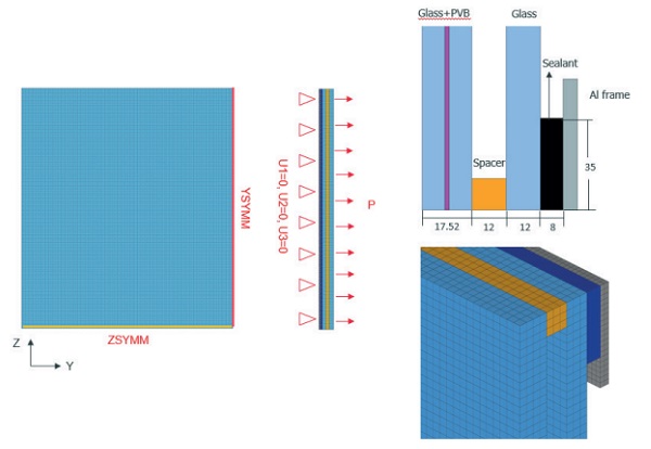
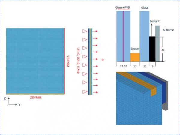
In a next step, a 3D curtain wall unit model was generated, which is composed of a glass panel, structural sealant, spacer and aluminum frame. Due to symmetry, a quarter of the unit was modeled (375x425mm²).
Typically, when analyzing the performance of the sealant, and in the absence of information on the frame, it will be modelled as a fully rigid support. This is the most severe case, as in the façade industry, the frames, especially unitized systems, will deform and hence reduce partially the stress and strain on the sealant.
The insulating glass units are composed of 8mm glass laminated with 1.52mm PVB (8.8.4), a cavity of 12mm and a monolithic glass of 12mm. The sizing of glass thickness was done to respect the maximal deflection requirement according to national standard JGJ102-2003 [18]. The permissible glass deflection should be the minimum of (Ls/60, 25mm) where Ls means length of the short span. In the current case, the minimum is 25mm.
The mesh size of the sealant layer in the model of the curtain wall is the same as the mesh size of H-bar model, i.e. 1 mm³. As the complexity of the project increases it is tempting to work with a coarser mesh to increase the speed of resolution of the calculation. However, as has been demonstrated [16], by doing so, stresses will be underestimated compared to reality. Should the project complexity impose the use of a coarser mesh to limit calculation time, then the H-bar calibration will need to be performed using the same coarser mesh as well.
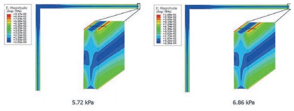
Boundary conditions include no movement at the plane of adhesion between substrates (glass, frame) and silicone. A uniform pressure of 1x and 1.2x times the design windload was applied at exterior surface of glass panel: 5.72kPa & 6.86kPa.
Von Mises stress and principal strain were chosen again as output for the sealant in curtain wall unit as shown in Figure 8 and 9. The local maximum level of the two examined criteria (Von Mises stress and strain) can be found at the middle of the long span, concentrated around the perimeter of the sealant. According to the modeling results as listed in Table 3, it was noted that the local maximum values are well below the benchmark values identified with H-bar (see Table 1) for 1X and 1.2x design wind load. Thus, the conclusion could be drawn that the design of structural sealant bite can meet designed performance expectation and even 20% more to account for future increase in strength and frequency of typhoons.
![Figure 8 Von Mises Stress [MPa]](/sites/default/files/inline-images/Fig8_63.jpg)

Conclusion
As the joint dimension used in the Ping An IFC project deviate from the calculation result according to ASTM C1401, FEA was used to verify the capacity of the joint to withstand the project windload.
Before modeling the project, a calibration exercise was performed to identify the values of strain and Von Mises stress, which were chosen as criterions for analysis. The same joint dimension and mesh were used as for the project model.
One year after completion, in September 2018, the super Typhoon Mangkhut hit the South China region. Many buildings in the region experienced damaged windows and doors, however Ping An IFC, the highest building in Shenzhen, successfully endured the event and remained unaffected and undamaged throughout the typhoon.
Structural sealant glazing technology and application has repeatedly demonstrated its structural resilience and long-term reliability based on historic evidence, even under the extreme environmental conditions. The high quality and safety performance of structural sealant glazing is realized through high performance sealant material, proper sealant joint design enhanced with the support of advanced calculation and modeling techniques, and more importantly, with systematic quality control in the sealant application process. Through its demonstrated capacity to enable aesthetic design and performance, structural glazing technology and application continues to earn its place to facilitate the vision to sit among the clouds and for high-rise facades to reach for the sky.
References
[1] Klosowski. J.M. and Wolf. A.T. (2009), “The History of Sealants”, Handbook of Sealant Technology, Taylor and Francis (CRC), Boca Raton, Florida, USA, pp. 3-25.
[2] Hilliard, J. R., Parise, C. J., and Peterson, C. O., Jr., “Structural Sealant Glazing”, Sealant Technology in Glazing Systems, ASTM STP638, ASTM International, West Conshohocken, PA, 1977, pp. 67-99
[3] 全球气候变化为强台风造就“温”床, http://www.cocc.net.cn/c/2018-10-08/50572.shtml
[4] Dario Trabucco, Angela Mejorin, Will Miranda, Reisuke Nakada, Christoph Troska, Ingo Stelzer, “Cyclone Resistant Glazing Solutions in the AsiaPacific Region: a Growing Market to Meet Present and Future Challenges”, GPD Glass Performance Days 2017
[5] 中国哪里台风多, https://www.tianqi.com/news/221603.html , 中国天气网
[6] Parise, C.J. and Spindler, R.G., “Structural Sealant Glazing in the 1980s,” Exterior Wall Systems: Glass and Concrete Technology, Design, and Construction, ASTM STP 1034, B. Donaldson, Ed., American Society for Testing and Materials, Philadelphia, 1991, pp. 94-117
[7] https://oceanservice.noaa.gov/facts/cyclone.html accessed 6th May 2019
[8] ETAG 002, Guideline for European technical approval for structural sealant glazing kits (2012), EOTA
[9] ASTM C1401
[10] GB 16776, AQSIQ, SAC, Structural silicon sealants for building (2005)
[11] GB50009-2001, Load code for the design of building structures
[12] Abaqus Analysis User’s Manual, Version 2017, Dassault Systèmes Simulia Corp., Providence, RI, USA.
[13] Next generation calculation method for structural silicone joint dimensioning, Descamps, P., Hayez, V. & Chabih, M. Glass Struct Eng (2017) 2: 169. https://doi.org/10.1007/s40940-017-0044-7
[14] Silicone joint dimensioning calculation methods, P. Descamp,s V. Hayez, Challenging Glass 6, Conference on Architectural Applications of Glass, Belis, Bos and Louter (Eds.), Ghent University , May 2018
[15] http://axelproducts.com/ accessed May 2019
[16] Structural Glazing: Design under High Windload, Challenging Glass 5, Conference on Architectural Applications of Glass, Belis, Bos and Louter (Eds.), Ghent University , June 2016
[17] Failure behavior of silicone adhesive in bonded connections with simple geometry, Y. Staudt, C. Odenbreit, J. Schneider, International journal of adhesion and adhesives, Vol 82, pp 126-138, 2018
[18] Technical Code for Glass Curtain Wall Engineering, China National Standard: JGJ102-2003.
NOTICE: No freedom from infringement of any patent owned by Dow or others is to be inferred. Because use conditions and applicable laws may differ from one location to another and may change with time, Customer is responsible for determining whether products and the information in this document are appropriate for Customer’s use. The product described in this literature may not be available for sale and/or available in all geographies where Dow is represented. The claims made may not have been approved for use in all countries. Dow assumes no obligation or liability for the information in this document. NO WARRANTIES ARE GIVEN; ALL IMPLIED WARRANTIES OR MERCHANTABILITY OR FITNESS FOR A PARTICULAR PURPOSE ARE EXPRESSLY EXCLUDED.
™® Trademark of The Dow Chemical Company (“Dow”) or an affiliated company of Dow.


