Authors: M.A. Samieian, D. Cormie, D. Smith, W. Wholey, B.R.K. Blackman, J.P. Dear & P.A. Hooper
Source: Exp Mech 63, 385–400 (2023). Springer
DOI: https://doi.org/10.1007/s11340-022-00927-6
Abstract
Background
The bending behaviour of laminated glass plays an important role in determining its overall response to blast loading. It is costly and difficult to characterise the bending behaviour by carrying out full-scale blast tests, therefore an alternative method is required.
Objective
The objective of this study is to understand the response of laminated glass under high-rate bending in the laboratory at rates representative of blast loading.
Methods
In this paper a novel testing method is presented in which laminated glass strips of 700 mm long by 60 mm wide are tested up to speeds of 10 m/s in the laboratory. The laminated glass is accelerated to speeds comparable to blast loading and then brought to rest at its edges to mimic impulsive blast loading conditions. Different interlayer thickness, impact speeds, and boundary conditions were explored. Additionally, modelling methods were used to study the flexural rigidity of post-cracked laminated glass.
Results
From the experiments it was found that the interlayer thickness plays a key role in determining whether the dominant failure mechanism is de-bonding of interlayer from the glass or interlayer tearing. In addition, it was found that by allowing the frame to bend under loading, the laminated glass can carry greater loads without failure. Finally, an iterative method was used to quantify the flexural rigidity of post-cracked laminated glass depending on the speed of travel. This is a novel finding as it is usually assumed that laminated glass behaves like a membrane in the post-cracked phase of the response.
Conclusion
In modelling and design of laminated glass structures under blast loading, post-crack flexural rigidity must be taken into account. Additionally, having novel frame designs to add further load bearing capacity to the framing members, plays a key role in reducing the load intensity on the laminated glass structure.
Introduction
Full-scale blast testing of laminated glass is very expensive, constraining the potential to conduct multiple tests with controlled variation of experimental parameters. As a result, such tests are often simply pass/fail exercises. At the same time, it is often difficult to replicate the blast loading conditions in the laboratory, making some aspects of laminated glass behaviour challenging to probe experimentally.
One of these experimental challenges is studying the bending behaviour of cracked laminated glass. This is a key characteristic of laminated glass that provides significant protection to building occupants in blast events [1]. The methodology proposed here addresses these difficulties through a lab scale test which mimics the impulsive loading conditions in a full-scale blast test and enables a detailed investigation of the bending behaviour of laminated glass at high rates of deformation.
Under blast loading, pressure waves propagate outwards from the centre of explosion. Such pressure waves can interact with structures such as buildings. This interaction causes damage to the building, including glazing which can shatter and turn into small glass fragments. These glass fragments can travel at high velocities, causing further damage and are hazardous to the building occupants. To mitigate the damage of blast loading on glazing systems at a minimum cost, laminated glass composites are often employed. Laminated glass composites for blast protection consist of a interlayer sandwiched between glass layers. PVB is the most common interlayer used, but it is not the only one. In protective design, after the pressure waves interacts with the laminated glass pane, the glass layers crack and the cracked fragments remain adhered to the interlayer. The interlayer then deforms to absorb the pressure waves. This can eventually lead to tearing of the PVB interlayer [2,3,4,5,6].
In glazing design, four factors are important; the glass pane, the framing members, the connection mechanism between the glass pane and the frame, and the connection mechanism between the frame and the building. The focus of this study is on the glass pane, in this case being a laminated glass composite. The behaviour of laminated glass under blast loading is usually studied in two distinct phases. The phase before the glass layers crack is referred to as the pre-cracked phase and the phase after the glass layers crack is referred to as the post-cracked phase. In the application of laminated glass for protection against blast loading, the post-cracked phase of the glass is of more significance because most of the energy is dissipated during this period. Under blast loading, the laminated glass pane experiences an almost uniform load across the pane and undergoes bending. The assumption has always been that in-plane tensile loads dominate [1, 7] (the pane acts like a membrane). Many authors have hence focused on the in-plane tensile loads that the pane experiences such as Sha et al. [8], Muralidhar et al. [9], Seshadri et al. [10], Samieian et al. [11] and Delince et al. [12]. However, under impulsive loading conditions in a full-scale blast test, the radius of curvature of the pane is significant and it is reasonable to expect significant resistance to bending even in a cracked laminated pane. Moreover, further bending resistance could be introduced at high strain-rates because the PVB interlayer will become stiffer, hence, there will be a composite bending response from the attached glass fragments in compression and the interlayer in tension [13,14,15].
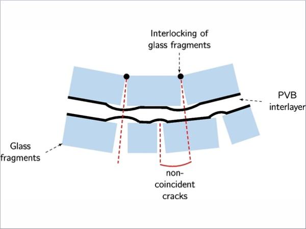
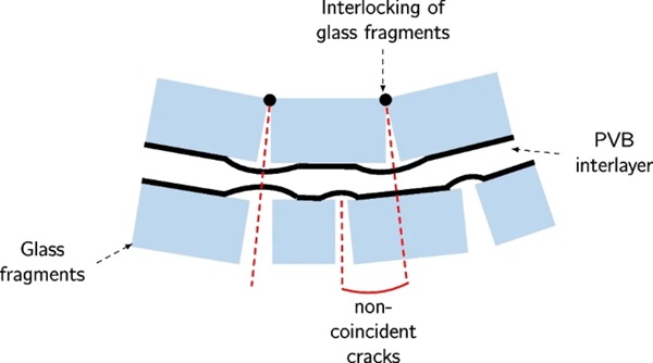
Understanding the bending behaviour of laminated glass is important particularly in the post-cracked phase. In cracked laminated glass, fragments are joined by PVB ligaments (Fig. 1). The tensile deformation of laminated glass happens through the extension of the ligaments and delamination of the PVB from the glass fragments. The crack pattern influences this deformation. In areas of high cracking density (small glass fragments) there are a higher number of ligaments available for stretching [16]. In low density areas, large fragments cause strain concentrations around the ligaments, leading to PVB tearing. However, there is little understanding of the effects of these deformation mechanisms on the laminate response in bending. In addition to the ligament deformation, load is also carried by the interlocking of glass fragments due to non-coincident cracks formed in the glass fragments on either side of the laminate. Finally, loading can also be carried through a composite bending response of the attached glass fragments in compression and the interlayer in tension. This depends on many factors such as the glass fracture pattern, interlayer thickness, adhesion grade, temperature and moisture [17].
The conventional experimental methods for testing materials in bending are the three-point and the four-point bending test methods. In such tests, the test specimen is supported using point contacts and then it is loaded at specific locations. For testing laminated glass, if assessing the strength of the glass prior to cracking is the sole purpose of the test, then three-point or four-point testing methods are appropriate at low rates. For blast loading applications, where loading rates are much greater, the conventional testing methods do not fully characterise the response as the inertia and high strain-rate effects are not captured, and the loading is not applied uniformly. This is particularly true in the post-cracking phase, where the laminated glass is assumed to behave like a membrane [1, 18,19,20,21]. The three-point and four-point bending tests have limitations at low and high testing rates. At low rates, the interlayer is viscoelastic, so enough stiffness cannot be achieved to make the test valuable. Similarly at high rates, because of the inertial effects of the cracked laminate, for the bending test analysis to be valid, quasi-static conditions are needed. Since quasi-static conditions are not met at high rates, the three-point and four-point bending tests become invalid.
Nevertheless, a number of researchers have addressed the four-point bending tests on pre-cracked laminated glass. In 1972 Hooper [22] carried out four-point bend tests at very low testing rates and more long term tests. More recently Aiello et al. [23] have carried out four-point bending tests on monolithic and laminated glass at low rates. Fam and Rizkalla [24] have conducted four-point bend tests on monolithic and laminated glass panes. Jalham and Alsaed [25] and Bati et al. [26] have investigated the effect the different interlayer thicknesses and different interlayer materials have on the performance of laminated glass under bending. Serafinavicius et al. [27] have also studied the effects of long term four-point bending tests on laminated glass with PVB, EVA and Dupont’s SentryGlas (SGP) interlayers.
Furthermore, several authors have looked into bending behaviour of post-cracked laminated glass. Kott and Vogel have assessed the response of specimens with PVB at low rates [13] Delince et al. have assessed the response of specimens with ionomer interlayers at low rates [12], Overend et al.have researched specimens with PVB and multiple glass layers at low rates [28], and Angelides et al. have recently researched the response of specimens with PVB at simulated high rates with low temperatures [14, 15].
The focus of research on the bending behaviour of laminated glass to date in the literature has been on four-point bend tests carried out at low-rates, which as previously mentioned do not well characterise the behaviour of laminated glass subject to blast loading. An alternative testing method which is a full-scale blast test, however, it is a time consuming and a costly process.
In this paper a novel testing method is proposed that allows the bending behaviour of laminated glass subject to uniform loading to be studied which is not as costly as full-scale blast tests. The objective of this study is to capture the behaviour of laminated glass under high rate bending. The effect of loading rate and interlayer thickness have been considered. In addition, the effect of boundary conditions on the bending behaviour has also been studied. A comparison has also been made to a finite element (FE) model, to determine the importance of bending resistance of the laminated glass pane in the post-cracked phase of the response.
To put this study into context, a brief explanation is given on the different methods of how uniform loading can be applied. This is then followed by presentation of the novel testing method, data analysis techniques and modelling methods. This is followed by the presentation of the experimental results and comparison of the model with experimental data. Finally, a joint discussion is made on the effectiveness of such experimental methods in capturing the bending resistance in post-cracked laminated glass subject to high rate loading and how it compares with the FE model.
Materials and Methods
Experimental Methods
Replicating impulsive blast loading
In blast loading, the two extreme types of response are categorised as the quasi-static loading case and the impulse loading case. In the quasi-static loading case the response of the structure is much shorter than the loading duration and in the impulsive loading case the response of the structure is much longer than the loading duration [19]. These two cases are best described using the natural period of the structure, T, and the duration of the positive phase of the pressure from a blast wave, 𝑡𝑑. In the quasi-static region, the duration of the positive phase is much greater than the natural period of the structure (𝑡𝑑 >> T). In the impulsive region, the duration of the positive phase is much smaller than the natural period of the structure (𝑡𝑑 << T).
Out of the two cases, the impulsive case is usually observed in blast experiments [29]. It is the more difficult case to replicate in the laboratory because it requires a high momentum to be imparted to the test specimen. The experimental setup here is replicating the impulsive loading case in an blast loading scenario.
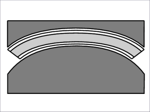
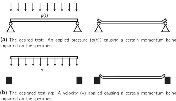
A blast wave leads to a uniform load on the surface of the concerned specimen, provided that the specimen is far away from the source of the blast wave. In order to achieve uniform loading without a physical contact, a uniform load in the form of pressure can be applied across the surface of the test specimen. When a uniform load is applied to the surface of the specimen which is held firmly at its edges, the specimen deflects in the out-of-plane direction at a given velocity (Fig. 2(a)).
The underlying idea behind the test rig is presented here (Fig. 2(b)). The test specimen and its fixtures are accelerated to a certain velocity, giving the same momentum it acquires during blast loading. At an instant later in the test, where the specimen is travelling at a certain velocity, the edges of the specimen are prevented from moving forward. The remainder of the specimen which is not prevented from moving, still has momentum and begins to deflect in the out-of-plane direction. The end result is that a uniform impulse (equating to mass x velocity) is applied to the test specimen.
The test rig
In addition to the uniform loading requirement, the tests must be carried out at high rates. This then ensures the tests are meaningful in relation to blast protection applications. According to blast test observations in the literature, the out-of-plane deformation velocity of the center of the laminated glass pane has been recorded to be in the range of 15−30 m/s [18]. This of course is dependent on many factors such as the glass mass per unit area and blast wave impulse. A similar order of magnitude can be achieved using a high rate servo-hydraulic Instron testing machine, such that the results are representative of full-scale blast tests. This machine is capable of accelerating test specimens to velocities of up to 10 m/s. This is lower than the reported values in the literature, however, it is a speed that is likely to be seen in real world blast scenarios and the full-scale blast tests reported in the literature represent a small range of possible values.
A test rig was designed that would accommodate the high-rate Instron testing machine (Fig. 3). In this testing arrangement, a glass specimen is held by a carriage which is accelerated in the downwards direction by the ram of the high-rate Instron testing machine. The underlying principle of this test is that a laminated glass specimen is accelerated using a carriage and the carriage is prevented from moving forward at an instant later in the test.
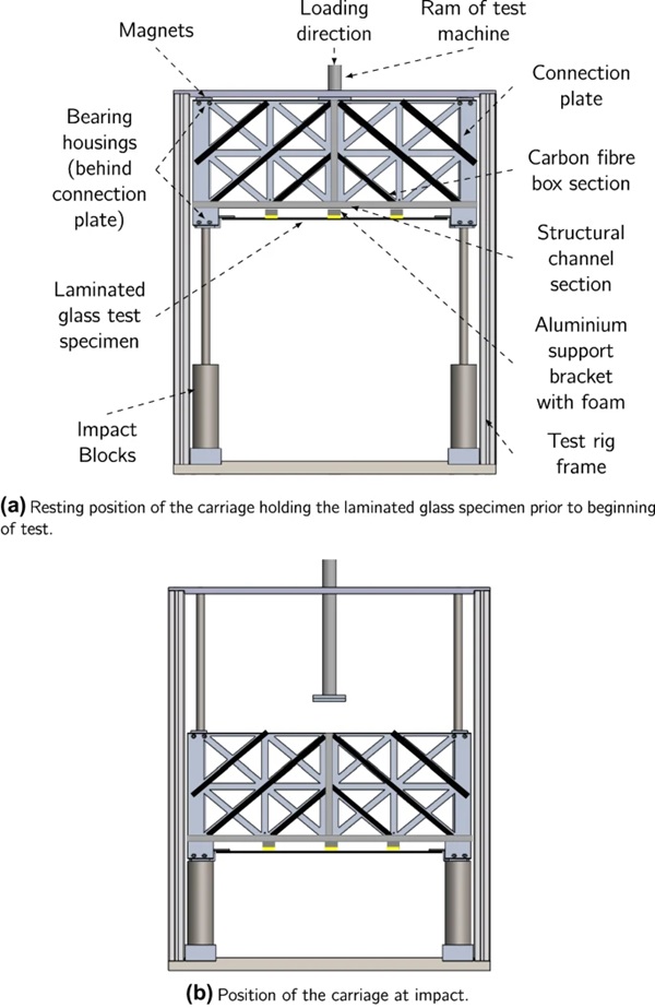
The carriage is initially held up against the frame of the test rig using magnets. The carriage along with the glass specimen is then accelerated by the ram to a pre-defined velocity1. At an instant later in the test, the sides of the carriage are promptly brought to rest by the impact blocks (Fig. 4 illustrates this prior to deflection of the specimen). The glass specimen which is supported at its edges on the carriage , then deflects in the out-of-plane direction because of the momentum imparted to the specimen. Note that the glass specimen does not directly impact against any object and the impact load is only provided through the initial acceleration of the carriage. In addition, in order to prevent the specimen from deforming during the acceleration phase, aluminium support brackets were connected on the carriage. To prevent damage to the glass specimen, a soft foam was used on the contact surface between the aluminium bracket and the glass specimen.

The carriage used for carrying the glass specimen is supported on four bearings housings which facilitate the sliding of the carriage on the two shafts. This carriage was made of two aluminium sheets acting as a ‘connection plate’ between the bearing housings. Structural features such as carbon fibre box sections and aluminium channel sections were added to the connection plate to increase its out-of-plane stiffness.
The Instron testing machine has a limitation on the specimen weight which it can accelerate, so it was not practical to test a square glass pane. Therefore, the test specimens used were in the form of a strip of laminated glass. This would allow the one-dimensional behaviour of laminated glass subject to high-rate uniform loading to be studied.
Test specimens
The experiments were carried out on laminated glass specimens comprising of three different PVB interlayer thicknesses, namely, 0.76 mm, 1.52 mm and 2.28 mm. Each interlayer was laminated with a 3 mm annealed glass layer on either side. The specimen was 700 mm long and 60 mm wide (see Fig. 5).
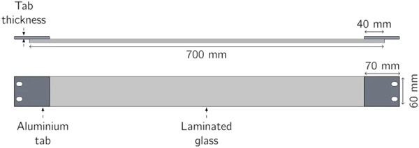
The laminated glass specimens were prepared using a standard lamination procedure by Kite Glass Ltd. The PVB used in the laminate was manufactured by Everlam. They were then cut to size by the glass manufacturer. The testing specimens were prepared by bonding the ends of the glass to aluminium tabs using an epoxy adhesive – Araldite 2021. Prior to applying the adhesive the surface of the glass and aluminium were grit blasted and cleaned with acetone. For attaching the specimens to the carriage, the aluminium tabs were bolted on the lower bearing housings of the carriage.
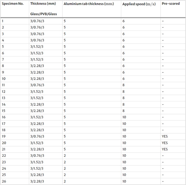
A total of 26 specimens were tested (Table 1). The thickness of each glass layer was 3 mm. The PVB thickness, however, was varied to allow the effect of interlayer thickness to be studied. Three different interlayer thicknesses were considered, 0.76 mm, 1.52 mm, 2.28 mm. Three different speeds of 6, 8 and 10 m/s were tested along with repeat tests at some conditions. These experiments were conducted on specimens with a aluminium tab thickness of 5 mm.
In addition to the experiments conducted on the normal specimens, two further specimen conditions were tested. The first condition was specimens which were pre-scored using a scribing tool, across the width on the outward side of each layer at a spacing of 62 mm along the length of the specimen (Fig. 6). This test was carried out to observe the effects of glass cracking at a lower stress upon impact on the response of the specimen in the post-cracking phase of the deformation. The second condition was specimens with a different boundary condition. The aluminium tab thickness was reduced to 2 mm in order to allow the aluminium tab to deform under loading. The purpose of these specimens were to study the effects of increasing the energy absorbing capabilities of the laminated glazing system as a whole unit.

Table 1 Test matrix - Full size table
Data processing
In this test, the displacement and the velocity of the laminated glass specimen were measured, prior to impact and during the deformation period. High speed video recording along with data analysis techniques on MATLAB [30] were used to calculate the displacement in number of pixels. Using a known distance in the image, the displacement in pixels was converted to displacement in mm.
The video recording was conducted in grey scale and the experiments were recorded from a side-on view. In order to distinguish the specimen from the background, the side of the specimen was painted in white, and a black card was placed in the background. Using an algorithm written in MATLAB, the edge of the glass specimen could now be detected at every point across the length of the specimen and between every time frame.
There was, however, an issue with some parts of the specimen. At the edges where extreme bending took place, small glass fragments would travel away from the specimen. These small glass fragments would interrupt the image and be falsely detected as the glass edge. This false detection results in a wrong displacement value. An example location where this problem would arise is shown as a blue line in Fig. 7. To overcome this problem, cross-correlation techniques were added into the data processing method.

An illustration is provided in this section to explain the data processing method. If the blue line along Fig. 7 is considered, it is possible to see that separated glass fragments interrupt the image. Fig. 8(a) shows the grey scale value along the blue line in Fig. 7. To obtain the true specimen edge, a cross correlation was calculated between a section of the image that was interrupted by separated glass fragments (Fig. 8(a)) and a clean part of the image from the central section (Fig. 8(b)). The maximum value in the cross correlation, represents the location of the edge of the specimen (Fig. 8(c)).
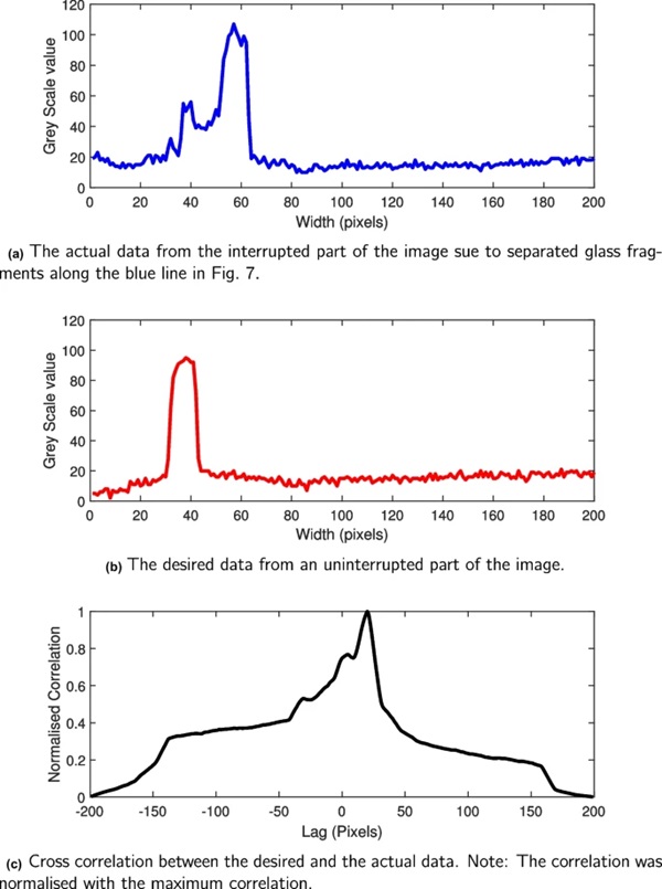
This procedure was repeated along the length of the specimen. This only gives the location of the top edge of the specimen, so the image was rotated by 180 degrees and the process was repeated again to find the location of the bottom edge. An average was taken between the bottom edge and the top edge and this value was used as the current location of the laminated glass. This was also repeated at every time step so that a displacement–time history for the specimen can be obtained.
Modelling Methods
A finite element model was created to allow a study of the bending resistance of laminated glass in the post-cracking phase of the deformation. A laminated glass composite consisting of three layers (glass/PVB/glass), was connected to aluminium end tabs. A velocity was applied to the laminated glass such that the aluminium tabs impacted onto a rigid steel impact block (Fig. 9).
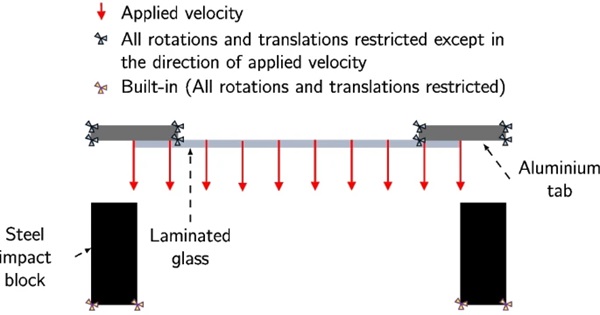
This FE model was compared only with the normal specimens that did not fail due to PVB tear or de-bonding (specimen numbers 1-10 and 12-15). The applied velocities which were examined were therefore 6 m/s and 8 m/s. The dimensions for the laminated glass were identical to the experimental specimens (700 mm long x 60 mm wide). The thickness of each glass layer was 3 mm. Three different interlayer thicknesses were considered (0.76 mm, 1.52 mm and 2.28 mm).
Material model
The modelling of laminated glass is a challenging task. The two distinct behaviours of glass and PVB, along with their interaction, complicate the material modelling process. Currently, two main approaches exist. The first approach is to treat each material and their interactions separately [31]. The second approach is to treat the laminated glass as a homogenous material and therefore treat the failure uniformly throughout the specimen [18, 32]. In the pre-cracked phase the two different modelling approaches are almost identical. In the post-cracked phase, however, differences exist.
Notable authors who have worked on modelling of laminated glass are Del-Linz [5], Del-Linz et al. [33], Hidallana-Gamage et al. [34], Larcher et al. [35, 36] and Zhang et al. [37].
One of the simpler materials models which characterises cracked laminated glass response udner blast loading and has been validated against blast test observations is that developed by Hooper et al. [1]. The validation was done against real blast test data using mid-span deformation and the panel deformation profile. The Hooper model assumes negligible bending resistance (flexural rigidity) for the glass layers in the post-cracked phase of the deformation. Strictly, this may not be true, as bending resistance can originate from many sources such as the interlocking of the glass fragments (Fig. 1). The modelling undertaken in this study is a modified form of the model developed by Hooper to take into account the bending resistance of the glass layers.
A shell model was constructed using three layers of glass/PVB/glass. For selecting the material model, it was assumed that a small amount of the deflection (less than 5% - see [19]) was spent in the pre-cracked phase of the response. Therefore the pre-cracked phase of the response was ignored and it was assumed that the post-cracking phase begins at impact. For the post-cracking phase of the response, the model developed by Hooper et al. [1] was selected.
In the Hooper model [1], the glass and PVB are treated separately. The glass component was treated as having elastic properties with negligible stiffness and hence no bending resistance. In the model presented here, however, this was modified to incorporate bending resistance. An iteration was carried out by incrementing the effective modulus (E) to find the correct values required for every impact speed such that the maximum deflection in the FE model corresponded to the experimental results (Table 4). Note the iteration was only carried out for the model with an interlayer thickness of 1.52 mm, and modulus value was kept constant when running the model for other interlayer thicknesses to find the maximum deflection at a given impact speed. It should be noted that in this model, crack locations have been ignored and uniform bending stiffness is assumed.
In the Hooper model, the PVB interlayer is modelled using elastic properties (Table 2) and a rate dependent Johnson-Cook plasticity model (equation (1)):

where σ is the stress, where ε˙ is the strain rate, ε˙0 is a reference strain rate, εp is the plastic strain and A, B, C and n are material constants. The material constants used in the model are shown in Table 3.
Table 2 Material properties used in the FE - Full size table

Table 3 Constants used in the Johnson-Cook plasticity model - Full size table

Table 4 The constants used for introducing bending resistance for the glass into the material model. *The flexural rigidity for each glass layer was also calculated as EI, where E is the effective modulus and I is the second moment of area - Full size table

Results
Experimental Results
A variety of results including two distinct failure modes were seen depending on interlayer thickness, impact speed, aluminium tab thickness and specimen pre-scoring. A summary of the results is shown in Table 5. In this experiment failure was defined as either de-bonding or PVB tearing.
Table 5 Summary of test results - Full size table
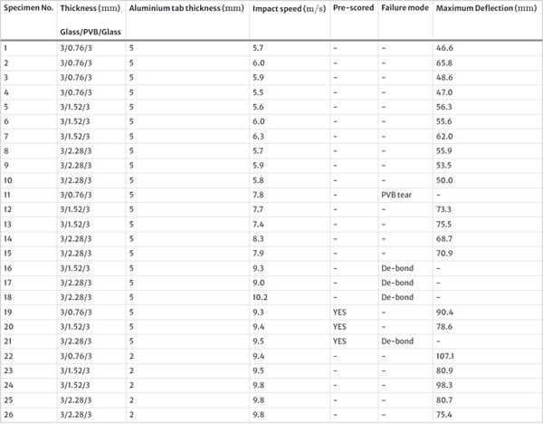
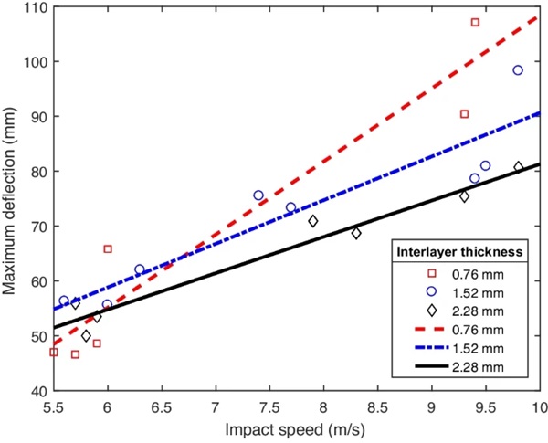
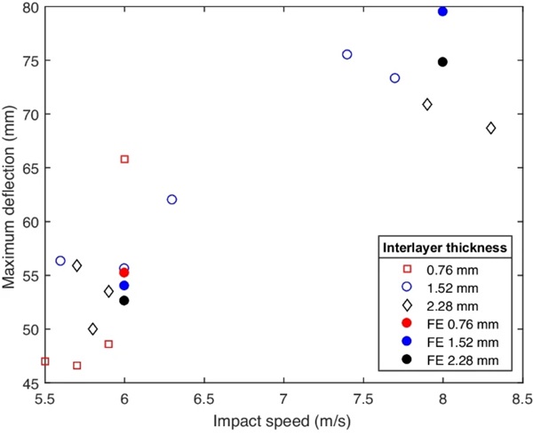
The deflection of the specimen was determined by the impact speed and the PVB interlayer thickness (Fig. 10). For a given impact speed and at a constant condition (normal, pre-scored or specimens with thinner aluminium tab), a greater deflection is achieved for specimens with a lower interlayer thickness. This was true for all test conditions, except for an applied speed of 6 m/s for specimens with a specimen thickness of 0.76 mm. As expected, a greater deflection was achieved for specimens tested at a greater impact speed.
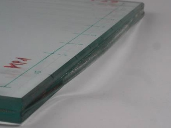
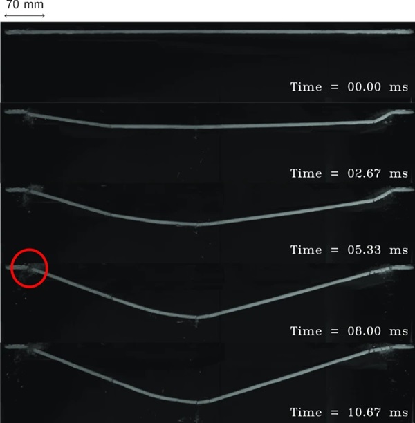
At a applied speed of 6 m/s all the specimens showed the expected behaviour. After impact, cracking in the glass along with stretching of the interlayer was observed. Furthermore, as the applied speed was increased, failure of some specimens became more evident. For example as the applied speed was increased from 6 m/s to 8 m/s, the specimen with the 0.76 mm interlayer failed due to the tearing of the interlayer (Fig. 11).
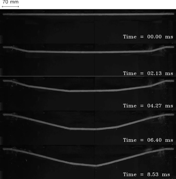
However, the specimens with 1.52 mm and 2.28 mm interlayers did not fail (Fig. 12). A typical displacement through-time along the length of the specimen is shown in Fig. 13.
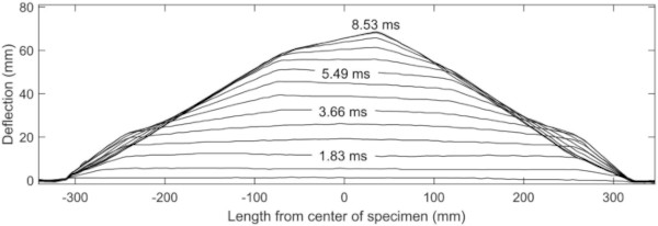
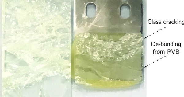
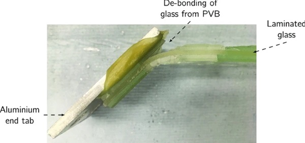
The applied speed was further increased from 8 m/s to 10 m/s. The specimen with the 0.76 mm interlayer was not tested again because it had already failed at speeds of 8 m/s, so there was no significance in testing at a greater speed. At 10 m/s the specimens with an interlayer thickness of 1.52 mm and 2.28 mm both failed due to delaminationFootnote2 between the PVB and the top glass ply along the edge of the specimen, followed by a minor region of cracking through the top ply of the glass (Fig. 14). This caused the full separation of the specimen from the aluminium end tab on one side. Note that the other side did not fail, however, de-bonding of PVB from the glass had already started (Fig. 15).
In comparison to the normal specimen, the scored specimens, which were all tested at an applied speed of 10 m/s showed an improvement in the response. The specimens with a 0.76 mm interlayer and 1.52 mm interlayer did not show any form of failure. The specimen with a 2.28 mm interlayer, however, still failed due to side delamination.
Finally, the specimens with a thinner aluminium tab thickness of 2 mm, which were all tested at an applied speed of 10 m/s, did not show any form of failure for all interlayer thicknesses. There was no interlayer tearing, and no delamination between the glass and the PVB. In addition a greater maximum deflection was achieved in comparison to all the other tested specimens.
Crack pattern
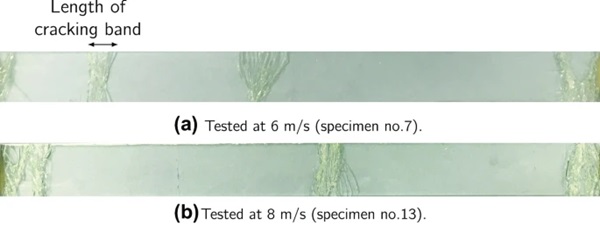
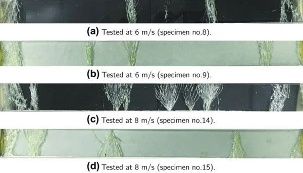
The post-cracking pattern of the glass showed that at greater speeds a longer band of cracking is generally observed, specially at the edges. This is illustrated for specimens with a 1.52 mm interlayer (Fig. 16), and also for specimens with a 2.28 mm interlayer (Fig. 17).
The specimens which were pre-scored to promote more cracking sites, did not actually crack along all the pre-scored lines. This was true for all the pre-scored specimens. An illustration for the specimen with a 0.76 mm interlayer tested at 10 m/s is shown in Fig. 18.

Modelling Results
The FE results are shown in Fig. 19. Similar to the experiments the FE results also showed to be dependent on the thickness of the interlayer and Impact speed. At greater impact speed, a greater maximum deflection was achieved.
Discussion
At higher impact speeds a greater maximum deflection is achieved because of the greater momentum imparted to the test specimen. This greater momentum could result in earlier crack initiation and propagation, allowing the interlayer to be exposed at an earlier time in the impact and therefore allowing for a greater deflection.
More interestingly, at a given speed and test condition, a greater maximum deflection was generally achieved for a lower PVB interlayer thickness. This is because for a given load, the thinner interlayer has a greater compliance and is therefore able to stretch more. This greater stretching could prove costly and lead to tearing at higher speeds because thinner interlayers carry a lower load. Tearing of the interlayer can also be initiated from the sharp glass fragments that are still attached to the crack-laminate [7, 38].
At the higher tested speeds, various modes of failure from PVB tearing to delamination on the edges started appearing. The specimens with a 0.76 mm interlayer tore, and the specimens with a 1.52 mm and 2.28 mm interlayer delaminated from the side of the glass layer. This could be because the glass was too strong for the speeds tested and thus this led to a lower number of glass cracking sites and hence a lower length of PVB available for stretching. This caused local strain concentration in the PVB which led to tearing of the PVB for the 0.76 mm interlayer.
In addition, this illustrates the competing mechanisms of tearing and de-bonding. For the specimens with a 0.76 mm interlayer the energy required to de-bond the PVB from the glass is greater than that required to tear the PVB. Therefore PVB tearing was observed. However, for the specimens with a 1.52 mm and 2.28 mm interlayer, the PVB is thicker and able to carry a greater load. So the energy required to tear the PVB is much greater than that required to de-bond the PVB from the glass. Therefore, delamination failure occurred in this instance.
Scored Glass Specimens
In order to promote further glass cracking initiation sites, the glass was scored. This solved the problem partially, and PVB tearing and delamination on the edges were no longer observed for the 0.76 mm and 1.52 mm interlayer. For the 2.28 mm interlayer, however, delamination was still present on the side of the specimen. The speed at impact for this specimen with a 2.28 mm interlayer was slightly greater than the 0.76 mm and 1.52 mm interlayer, but this could not be the only reason.
Thinner End Tab Specimens
The final testing arrangement used the thinner 2 mm aluminium end tabs, instead of 5 mm, to connect the glass specimen to the carriage. All the failure modes observed previously, such as PVB tearing and side delamination, were no longer present. This was true for all interlayer thicknesses. This is because some of the energy from the load is absorbed through the plastic deformation of the aluminium end tabs, which leads to lower stresses being experienced by the laminated glass. The idea behind this testing arrangement was to explore new design possibilities on framing members of a laminated glazing system such that the frame is purposely designed to undergo plastic deformation under loading. This intentional plastic deformation increases the blast resistant capabilities of the laminated glazing unit as a whole.
Furthermore, on the specimens with the thicker 5 mm aluminium end tabs, the two failure modes of interlayer tearing and de-bonding occurred close to the edges. The thinner 2 mm aluminium end tabs allow for rotation at the edges as they bend and absorb energy, hence reducing the localised loading intensity at the edges of the laminated glass specimen. This bending of the aluminium end tabs also causes the end boundary to act more like a simple support rather a built-in boundary condition – hence reducing the bending moments in the structure.
Post-impact Observations
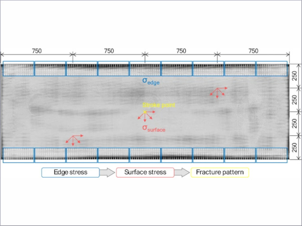
On observing the specimens post-impact, the first impression is that there is no relationship between the number of cracks formed in the glass specimen in relation to the impact speed. However, further considerations suggest that this is not the case. Firstly, it is important to distinguish between the two crack types formed on the glass specimens. The two crack types are termed “spreading cracks” and “uniform cracks” (Fig. 20). The “spreading cracks” spread from a single point at the edges, suggesting they have been initiated from a site of stress concentration at the edges possibly due to edge/surface condition. On inspection, most of the “spreading cracks” were on the upper side of the specimen – suggesting that they had failed in tension on the rebound. Whereas, the “uniform cracks” seem to have formed earlier on in the test, as a results of the travelling of the longitudinal stress waves.
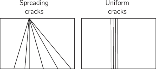
In addition, at greater impact speeds, a longer band of “uniform cracks” were seen along the length of the specimens. This is because at greater speeds, a greater deflection is achieved. To achieve this greater deflection, a greater rotation is required at the edges. As a result, a wider region of uniform cracks are formed.
The main assumption up to now has always been that there is no bending resistance from the glass layers in the post-cracking phase of the response [1, 19]. However in this experiment, the bending resistance of the glass layers varied depending on the intensity of the load. This is because the intensity of the load determines the number of cracks formed and the cracking density. These two factors will then cause bending stiffness to develop in the glass. At lower speeds, this bending resistance is more apparent.
The material model used in the FE has its limitations. The material model assumed a uniform material properties along the length of the specimen. However, this is not accurate, when comparing with the crack pattern from the experiments. The experimental specimens did not crack uniformly along the length. The size of the crack and crack density were both different.
Comparison to Full Scale Blast Test
In comparing this test rig to a real blast test, the rig has some advantages and some limitations. The advantages are that a uniform load is applied, which also resulted in a similar deflected shape in comparison to blast test observations. Additionally, this experiment can be carried out at a lower cost compared to blast testing, allowing a study of many different testing variables.
This testing arrangement also has its limitations. The cracking pattern was not similar to the cracking pattern of specimens from a full scale blast test observation. The number of cracking sites were smaller in comparison to crack patterns in a full scale blast test. In a blast test, cracks are observed over the entire panel surface. This could be because the speeds achieved in a blast test are approximately two or three times greater. In addition, in the experiments carried out here the cracking sites formed as a result of bending and local stretching of the specimen. Furthermore, the fact that the specimens tested here were only one-way spanning, meant that the glass was primarily loaded in one direction and hence the cracking pattern was affected.
Conclusion
In this study, a test rig was designed to replicate impulsive loading conditions in a full-scale blast test. Specimens with three PVB interlayer thicknesses were tested at three impact speeds. Normal uncracked glass specimens were used. Some specimens were pre-scored to promote cracking sites. A further testing arrangement was conducted on thinner aluminium end tabs. Finally the results from the normal specimens were compared to an FE model.
The common assumption to assume the laminate acts as a membrane in the post-crack phase [1, 19,20,21] was shown to be false in this study. This assumption is based on blast observations where the loading intensity is very high, such that the glass cracks all over the pane. However, it has been demonstrated here that the bending resistance of the glass layers is significant and that the flexural rigidity is dependent on the cracking density and pattern in the glass. The flexural rigidity of cracked laminated glass was found to be 40 GPa mm4 and 6.75 GPa mm4 at impact speeds of 6 m/s and 8 m/s, respectively.
This study demonstrated the competing mechanisms in the failure of laminated glass which is determined by the thickness of the interlayer. With a thinner interlayer, laminated glass is more likely to fail due to the tearing of the interlayer. Whereas with a thicker interlayer, laminated glass is more likely to fail due to de-bonding of the PVB at glass edges.
Frame design was also found to be an important additional factor which can impact the load bearing capabilities of the laminated glass. Here, it was demonstrated that with thinner aluminium end tabs, the likelihood of failure at higher speeds can be reduced by allowing framing members to absorb part of the impact energy. This could lead to novel framing designs and the idea of ‘sacrificial frames’ – where the frame is purposely designed to absorb energy under loading, hence reducing the loading intensity on the laminated glass pane.
Notes
- The applied speed selected on the machine results in a different impact speed. This is because of the nature of the testing machine, not producing exact speeds at high testing rates.
- Delamination is a term used to indicate the de-bonding of the glass from the PVB interlayer.
Acknowledgements
The authors acknowledge EPSRC (Engineering and Physical Sciences Research Council) and Arup Resilience, Security and Risk for supporting Mohammad Amin Samieian for his PhD. The authors also appreciate the work of Leroy Reed at Kite Glass Ltd for providing and manufacturing the laminated glass specimens.
Author information
Authors and Affiliations
- Department of Mechanical Engineering, Imperial College London, London, SW7 2AZ, UK - M.A. Samieian, B.R.K. Blackman, J.P. Dear & P.A. Hooper
- Arup Resilience Security & Risk, 13 Fitzroy Street, London, W1T 4BQ, UK - D. Cormie, D. Smith & W. Wholey
Corresponding author
Correspondence to M.A. Samieian.


