Article Information
- Digital Object Identifier (DOI): 10.47982/cgc.9. 613
- Published by Challenging Glass, on behalf of the author(s), at Stichting OpenAccess.
- Published as part of the peer-reviewed Challenging Glass Conference Proceedings, Volume 9, June 2024, 10.47982/cgc.9
- Editors: Christian Louter, Freek Bos & Jan Belis
- This work is licensed under a Creative Commons Attribution 4.0 International (CC BY 4.0) license.
- Copyright © 2024 with the author(s)
Authors:
- Xiaohan Hao - Tongji University
- Suwen Chen - Tongji University
Abstract
Anticlastic glass surfaces play a significant role in free-form glass facades. For realizing anticlastic surface, cold bending by loading at the corner of the plate is more adaptive and more economic than the traditional hot bending method. Previous research on anticlastic cold bending mainly focuses on the description of instability phenomenon and qualitative analysis of parameters. However, the failure mechanisms of glass plates during cold bending and the influence of lamination remains unclear. In this paper, the anticlastic cold bending test was conducted to explore the influence of various factors, including aspect ratio, scale and composition of the plates.
Subsequently, an effective finite element model was established and validated by test results, which is used for further explore the cold bending controlling condition for better engineering practice. The failure modes are considered as instability and strength failure. For laminated glass, maximum stresses can be derived from monolithic glass based on equivalent thickness method. The instability is induced by the compression area in the middle surface of glass plate which is significantly influenced by the composition of the laminates. Consequently, thin glass laminates exhibit enhanced stability because a reduced glass to PVB thickness ratio changes the compression area from bi-directional to uni-directional.
1.Introduction
The free-form glass facades require double curved glass elements, and anticlastic glass is difficult to produce. The traditional hot bending method realizes the desired curvature using a prefabricated mould and high-temperature heating. Cold bending is a more economical and adaptive method for producing anticlastic glass plates. During this process, forces are applied at the corners of the glass plate while the other corners are fixed in an out-of-plane direction. (Eekhout 2010; Eekhout and Niderehe 2010; Neugebauer 2014; Bijster et al. 2016)
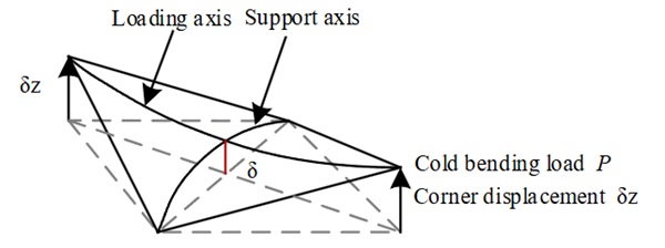
Existing research mainly focuses on the stability of glass plates, including the identification of instability phenomena, the prediction of instability occurrence and the analysis of influencing factors. Staaks and van (2004) discovered that during cold bending the deformation of glass plate concentrates in one diagonal, resulting in an asymmetric configuration. This configuration is commonly adopted by researchers as a symbol of instability occurrence. Dimension of the glass panel, the support condition, gravity and initial defect are the main factors affecting the cold bending stability. A linear relationship between the cold bending corner displacement at the instability point and the thickness of the monolithic glass plate has been observed (Benjamin 2015; Mainil 2015; Datsiou and Overend 2016; Spagnoli et al. 2019; Bensend 2016). Generally, point support has better deformation capacity compared with frame support (Benjamin 2015; Datsiou and Overend 2016; Bensend 2016). Gravity cannot be ignored when the panels are placed horizontally (Benjamin 2015; Datsiou and Overend 2016; Bensend 2016; Datsiou 2017). The initial defect makes the stability of the plate worse (Benjamin 2015).
Datsiou (2017) defined the asymmetric configuration as the change of deformation mode and then divided the cold bending instability modes into 3 types: the change of deformation mode, global snap-through instability, and cold bending distortion, and attempted to establish a unified failure controlling condition. But the global snap-through is actually a normal curvature change under gravity which is not regarded as instability in this paper. Some tests have proved that laminated glass, especially laminated thin glass, has better cold-forming capacity (Mainil 2015; Caprili et al. 2017), however, the contribution of the interlayer on cold bending stability remains unclear. Galuppi et al. (2014) proposed a bidirectional cylindrical model and enhanced effective torsion thickness method (Galuppi and Royer. 2020; Galuppi and Royer 2021) to study the instability of point supported glass elements during cold bending.
In summary, previous research has identified the changes in deformation mode and the main affecting factors on stability, such as support conditions, gravity induced-initial deflection, geometric dimension and lamination. However, characterizing the failure mechanism and quantifying the influences of these factors are necessary before applying anticlastic cold bending in practice.
To address these issues and systematically study the controlling condition for anticlastic cold bending, a series of cold bending tests were firstly conducted, then the influence of laminate composition, scale and aspect ratio on cold bending failure are investigated employing the FEM method. The instability mechanisms of laminated glass are discussed based on the results of experimental study and parametric analysis.
2. Cold bending test
2.1. Introduction
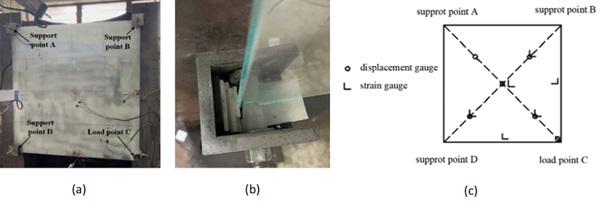
Cold bending tests were conducted in this paper to produce anticlastic shapes. The cold bending force is applied at one corner (C) of glass plate by manually turning the screw while the other 3 corners (A, B and D) are restrained locally (Fig. 2a). The loading rate is about 1 mm/s. Single-point loading and two points loading barely make a difference in the cold bending process. The corners of the glass plate are supported on a spherical jig which only limits the out-of-plane displacement through point contact and does not limit any in-plane displacements (Fig. 2b).
The out-of-plane cold bending force is very small, and the tension of the traditional displacement gauges will affect the out-of-plane performance, so the CMOS-1L laser displacement gauges are used. Right angle strain gauges are used to capture the strain development during cold bending. The weighing sensor is calibrated and has a range of 20kN with an accuracy of 0.1%. As shown in Fig. 2c, the displacement gauges are placed mainly along diagonals to capture the cold bending configuration. The stress gauges are placed mainly at the edges of glass plate to record the maximum stress.
The float glass plates have been polished at the edges to reduce the possibility of premature failure from edge flaws. PVB, Trosifol BG R20, is used in laminates for cold bending because of its flexibility. Monolithic glass plates are coated with high-adhesion film to prevent accidental splashes.
In order to explore the influence of aspect ratio, scale and laminate composition on the cold bending, the specimens are carefully designed, as listed in Table 1.
2.2. Test results and analysis
The failure mode, failure corner displacement (δz), failure load (P) and maximum principal tensile stress at the mid-edge of glass plates (б) are listed in Table 1.
Table 1 Test specimens and key results.
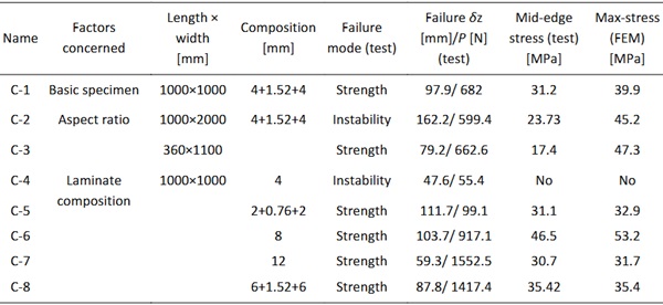
Two failure modes have been observed in the cold bending test, including strength failure and instability. The test results show that the 1000×1000×4 mm glass plate failed due to instability instead of strength because the stress caused by cold bending thin glass is small. For another instability-failed specimen, the 1000×2000×(4+1.52+4) mm laminated glass plate, strength failure closely follows the occurrence of instability. The other specimens failed due to strength failure.
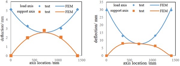
The instability can be identified when the configuration of the plate changes from symmetric to asymmetric, as shown in Fig. 3.
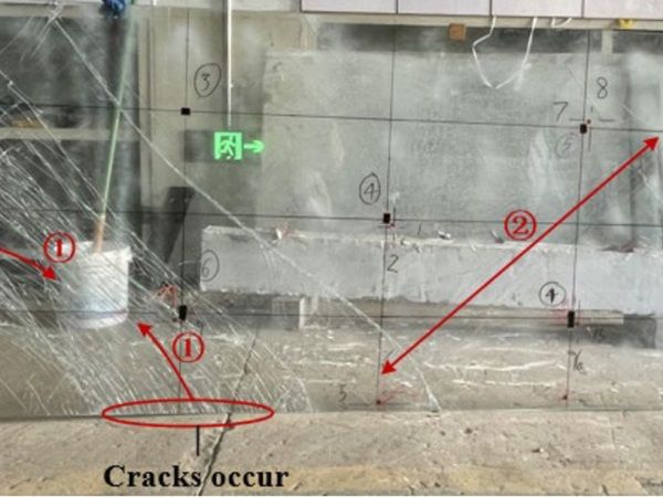
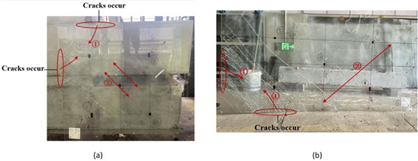
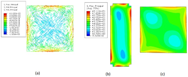
Glass cracks occur primarily along the two diagonal directions before instability due to stress concentration at the edges of the glass plate (Fig. 4). For the mid-surface of the plate, the maximum stress is concentrated in the middle of the plate edge. This is because the plate tends to form a hyperbolic paraboloid in the point loading mode, so the center area of the plate is compressed along the two diagonal directions, and the edges of the plate are in tension (Fig. 5a). However, the maximum principal stress is larger on the top and bottom surfaces compared to the mid-surface surface due to bending and torsion, and the location of maximum principal stress moves along the edge of the plate as the plate deforms (Fig. 5b,c). The location of maximum principal stress moves away from the mid-edge of glass plates and gets closer to glass corners when the aspect ratio is larger. This explains the difference between mid-edge stress from test and maximum stress from FEM for the cases of C-2 and C-3 in Table 1.
3. FEM model
3.1. Model building
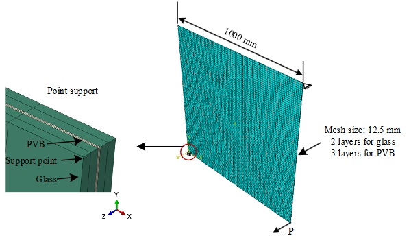
Finite element models are developed using ABAQUS. The material properties of glass are simplified into elastic, and the corresponding parameters are presented in Table 2. The Ogden hyper-elastic material model is used to model PVB. Glass adopts C3D20R solid elements, while PVB adopts C3D20RH hybrid elements. The size of the mesh is set at 12.5×12.5 mm. The glass and PVB are divided into two and three layers along the thickness, respectively (Fig. 6).
Table 2: Material models and key parameters.

The constraints at the corners of the glass plate (Fig. 6) only restrict the out-of-plane displacements while allowing for in-plane displacements and rotations. The PVB-to-glass connections are assumed to be tie, without considering the debonding slip. Displacement loading protocol is applied. During the cold bending process, the maximum stress of glass plates is concentrated at the edges of the top or bottom surface. The edge strength of float glass is set as 22MPa in the Finite element model according to Chinese standards (JGJ 113-2015).
The asymmetric configuration and maximum principal stress of glass plates are monitored during the cold-forming process. When the plate’s center deflection changes nonlinearly, the plate loses its symmetry, indicating that instability has occurred. When the maximum stress reaches 22MPa, the specimen cracks, indicating the strength failure.
3.2. Model verification
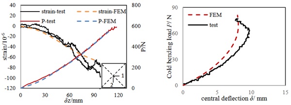
The configurations from FEM before and after instability, in comparison with test measurement, are shown in Fig. 3. The relationship of cold bending load (P) with corner displacement (δz), central deflection (δ) and strain (ε) from the FEM and test results are showed in Fig. 7. The strain at the center of the glass plate in both 1 and 2 directions are similar because of the symmetrical nature, which validates the effectiveness of the test. The P-δz, ε-δz andP-δcurve obtained from the numerical analysis are in good agreement with the experimental results, indicating the effectiveness of the built finite element model.
4. Influencing factors
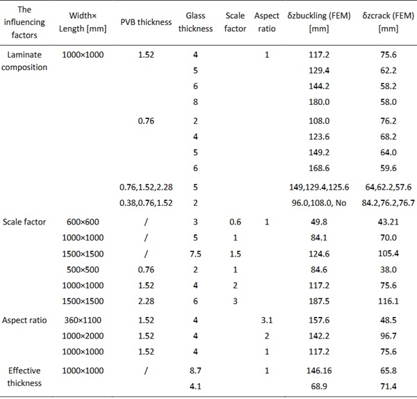
Further parametric study is carried out with the validated finite element model. Laminate composition, scale factor and aspect ratio are considered. Table 3 presents the key results from parametric studies for each case, including the cold bending corner displacement when maximum stress in glass plates is corresponding to crack (δzcrack) or instability (δzbuckling).
Table 3: Key results from the parametric study.
4.1. Laminate composition
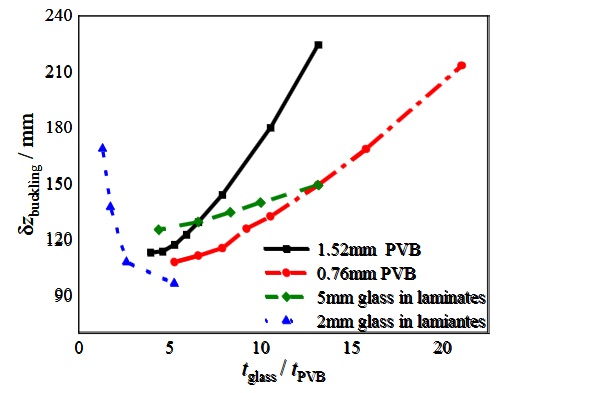
The relationship of δzbuckling and tglass/tPVB for different laminate compositions is shown in Fig. 8. Obviously, laminated glass plates have better deformation capacity compared with monolithic glass plates. A larger glass-to-PVB thickness ratio results in larger corner displacement at the instability point. But for laminates with 2mm glass, the opposite phenomenon is observed that larger glass-to-PVB thickness ratio results in smaller corner displacement at the instability point.
4.2. Scale factor
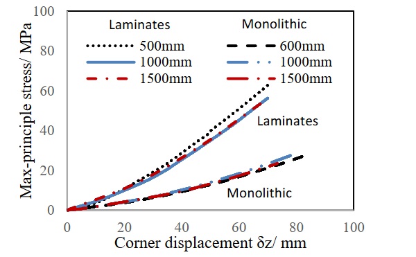
Changing the aspect ratio will inevitably change the scale size simultaneously. The influence of varying scales needs to be analyzed first. Fig. 9 shows the specimens with different scales but the same aspect ratio. Taking the ratio of the cold bending displacement divided by the scale factor as the x-axis, the stress-displacement curve exhibits the same trend for both monolithic and laminated glass plates. The ratio ofδzbucklingto scale factor is similar for monolithic glass plates, but not for laminated glass plates (Table 3). The scale will influence the stability of laminated glass because of the hyper-elastic adhesive PVB.
4.3. Aspect ratio
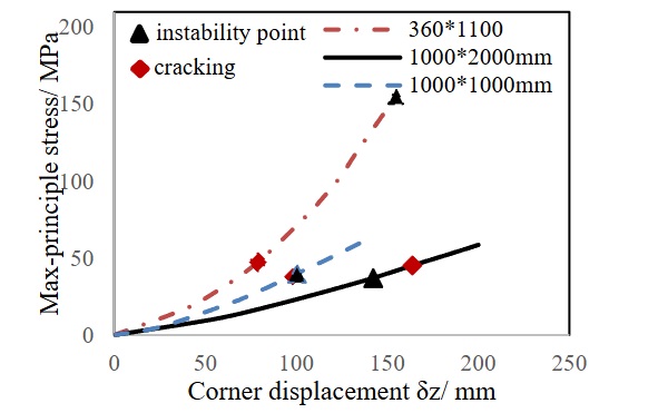
Fig. 10 shows the cracking stress obtained from test results and instability point obtained from FE analysis for (4+1.52+4) mm laminated glass plates with varying aspect ratios. The corner displacement at instability δzbuckling increases with larger aspect ratios. As shown in Figure 5b and Figure 5c, the location of maximum principal stress moves away from the mid-edge of glass plates and gets closer to glass corners when the aspect ratio is larger.
5. Influencing mechanism of lamination on instability
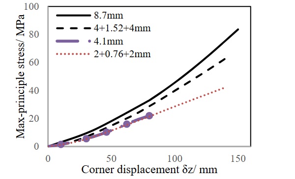
An effective torsion thickness method has been proposed for the stress calculation of laminates by (Galuppi and Royer 2020; Galuppi and Royer 2021). Fig. 11 compares the stress evolution of laminated glass plates and monolithic glass plates with effective torsion thickness. The effective torsion thickness is 4.1 mm for 2+0.76+2 mm laminates and 8.7 mm for 4+1.52+4 mm laminates. The results show that the effective torsion thickness method for stress calculation is applicable to the cold bending process.
Though the effective thickness method can be used to estimate the maximum principal stresses of the laminates, the stability of the laminated glass plate differs from that of monolithic glass. The influence of lamination on stability will be analysed in the following.
A laminated glass plate with a laminate composition of 800×800×(5+0.76+5) mm is selected for illustration. As shown in Fig. 12, the stress is the superposition of bending stress and membrane stress. The middle surfaces of both top and bottom glass plates in laminates are compressed in two diagonal directions during the cold bending process, but the compressive stress distribution differs along two diagonals due to the influence of monolithic bending. The instability is caused by the collapse of the bi-directional compression area at the center of the plate.
Fig. 13 presents the stress distribution of 1000×1000× (2+0.76+2) mm laminate during the cold bending process. The layered bending stress and membrane compressive stress are minimal, while the monolithic bending stress is obvious. Therefore, the mid-surface of the glass will always be under tensile along one diagonal. Different from monolithic glass, the cold bending deformation is larger before instability because of the disappearance of the bi-directional compression zone in the middle surface of the glass, then the edge of the plate cannot remain straight before instability. However, the plate is still self-balanced and has stable bearing capacity before instability.
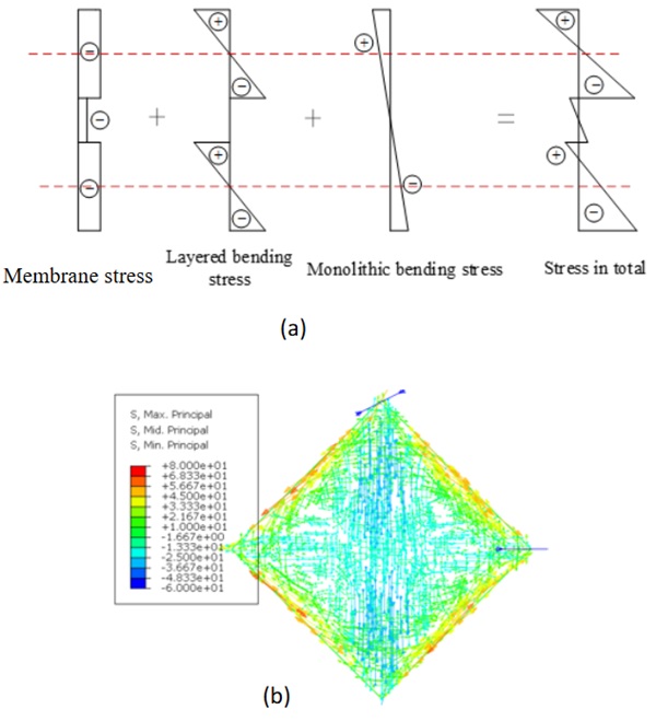
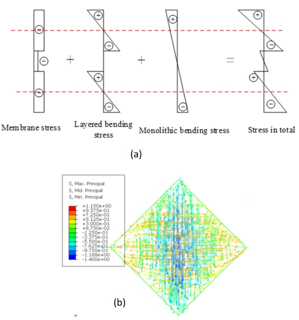
Based on the above analysis, the instability of laminated glass plates is caused by the collapse of a bi-directional compression area or unidirectional compression area in the middle surface of glass plates. The two stress distributions explain the varying characteristics of instability for laminated glass with different glass-to-PVB thickness ratios.
6. Summary and outlook
In this paper, cold bending tests are conducted to investigate the influence of laminate composition, aspect ratio, and scale. Finite element models are established and verified, and then followed by parametric analysis. Analysis results are summarized as follows:
- Two failure modes, strength failure and instability, have been observed in cold bending test.
- Laminated glass plate has better stability compared to monolithic glass plate. Larger glass to PVB thickness ratio results in larger corner displacement at the instability point. But for laminates with 2mm glass, opposite phenomenon is observed that larger glass to PVB thickness ratio results in smaller corner displacement at the instability point.
- The corner displacement at instability increase with larger aspect ratio and scale factor. The maximum principal stress locates away from the mid-edge of glass plates and closer to glass corners when the aspect ratio is larger.
- The instability of laminated glass plates are caused by the collapsed of bi-directional compression area or unidirectional compression area in the middle surface of glass plates.
- However, there are still some issues need further analysis. Criteria for controlling anticlastic cold bending need to be proposed for monolithic and laminated glass plates. A unified standard is possible with the introduction of equivalent torsion stiffness. Moreover, it’s necessary to clarify the boundary between the two stress distribution-controlled instabilities for laminated glass plates.
References
Benjamin, M., Cold-Bent Glass Structures. Ecole Polytechnique Federale Delausanne-Icom (2015).
Bensend, A.: Maximizing the Twist of Cold Formed Glazing. Challenging Glass 5-Conference on Architectural and Structural Applications of Glass (2016).
Bijster, J., Noteboom, C., Eekhout, M.: Glass Entrance Van Gogh Museum Amsterdam. Glass Structures & Engineering, 205–231 (2016).
Caprili, S., Mussini, N., Salvatore, W.: An innovative solution for hybrid steel-glass self-bearing modular systems. Journal of Constructional Steel Research 130, 159–176 (2017).
Datsiou, K.C., Overend, M.: The mechanical response of cold bent monolithic glass plates during the bending process. Engineering Structures 117, p. 575-590 (2016).
Datsiou, K.: Design and Performance of Cold Bent Glass. Cambridge (2017).
Eekhout, M., Lockefeer, W., Staaks, D.: Design and Build of a Warped Tram Station. Challenging Glass 2 – Conference on Architectural and Structural Applications of Glass (2010).
Eekhout, M., Niderehe, S.: The Cold Bent Glass Roof of the Victoria & Albert Museum. Challenging Glass 2 – Conference on Architectural and Structural Applications of Glass, London (2010).
Galuppi, L., Massimiani, S., Royer-Carfagni, G.:Buckling phenomena in double curved cold-bent glass. International Journal of Non-Linear Mechanics 64, 70-84 (2014).
Galuppi, L., Royer-Carfagni, G.:Enhanced Effective Thickness for laminated glass beams and plates under torsion. Engineering Structures 206, (2020).
Galuppi, L., Royer-Carfagni, G.: The Effective Thickness of Laminated Glass Plates. (2011).JGJ113-2015, Technical regulations for the application of architectural glass. (2015).
Mainil, T.:Exploratory investigation on the cold bending of thin glass. Gent (2015).
Neugebauer, J.U.:Applications for Curved Glass in Buildings. Journal of Facade Design and Engineering 2. 67-83 (2014).
Spagnoli, A., et al.: Geometrically non-linear bending of plates:Implications in curved building façades. Construction and Building Materials 214, 698–708 (2019).
Van Herwijnen, F., Staaks, D., Eekhout, M.:Cold Bent Glass Sheets in Façade Structures. SEI Discussion 14 (2004).

