First presented at GPD 2019

Abstract
The Glass structure of the West Balustrade in Eleftherias Square Nicosia Cyprus presented a challenge to Pentagonal in terms of 3D modelling, special glass fittings fabric, glass production, installation and testing in order to achieve the goal of this long waiting project. The design and construction of this prominent and futuristic design by Zaha Hadid Architecture project required input and expertise from Architects, Structural engineers, Software engineers, Glass specialists engineers and General contractor builder.
Project Overview
A glass balustrade may be more than the functional propose, may be a land mark or point of cultural reunion creating an urban plaza for the city of Nicosia connecting both sides in the last divided capital of Europe. Todays architectural demand for complex geometry has been developed to attain maximum transparency in more organic forms to improve the wellbeing of users and maximize interaction with the outside.
This glass balustrade was produced by Pentagonal and has an inclination of 42 along its length with non regular curved geometry to create a glass balcony faced to west. Structural glass elements and software modelling were specifically developed, simulated and tested to ensure that not only the structural but also the aesthetic performance of the glass structure is guaranteed. The architecture design was made by Zaha Hadid studio modeled and manufactured by Pentagonal Fitechnic systems with Eckersley O Callaghan and Hyperstatic structural engineering, general contractor was LOIS Builders from Cyprus.


Balustrade Design
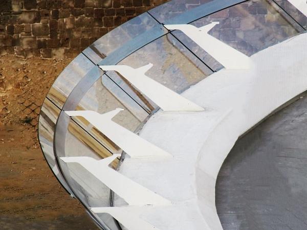
The scope of work for Pentagonal was to construct a glass balustrade with variable curved geometry composed by 20 metallic (mild steel painted) posts, fixed on an embedded plate (on concrete); with infill of 10+10mm glass laminated with interlayer Sentryglas posed in a stainless steel bottom shoe channel (stainless steel AISI 316) and fixed between posts by a superior patch fitting plates (stainless steel AISI 316) connected to the posts.
The balustrade is an inclined 42 glass panel cantilevered in a variable height from a bottom continuous channel and fixed on top aprox. 400mm from the edge with 2 stainless steel pates connected to a mild steel, to create a 1,10m height barrier.
The primary elements of glass balustrade are described below, and are as follows:
1. Mild steel embedded plate castin placed located on site before installation of balustrade
2. Mild steel metallic posts painted in color RAL
3. Welded stainless steel anchor plate with blocks for threaded holes bottom shoe (int)
4. Welded stainless steel L plate with countersunk bolts on the bottom shoe (ext) with whip holes to allow for drainage
5. Welded superior stainless steel plate (Ext) with blocks for threaded holes
6. Welded Stainless steel A1 hardware to Superior Ext Stainless steel plate
7. Welded stainless steel T arm connection
8. Connecting patch fitting A2 hardware
9. Welded superior stainless steel plate (int) with countersunk holes
10. Curved and straight laminated fully toughened glass 10+10mm with SGG Bright silver coating and Sentryglas interlayer
Detail Design
Glass panels modeled with variable sizes and shapes aprox. 3,50m length and 1,70m height were supported by an off the shelf profile bottom shoe channel with the capability to withstand the wind and snow loads to a deflection limit set at L/120 and maximum 25mm for barrier loads. No deflection design criteria was considered for seismic and the panels were restrained with structural silicone.
The dead load of the panels was supported by 2 or 3 (for curved glass) nylon bearing blocks per panel located on the bottom connection and also blocks on the top connection. The glass was produced with notches concealed by the capture plates, to allow for structural connection.
For the end panels located in of the west balustrade, a 5,8m glass length was installed but partially not supported by the bottom shoe so the dead loaded was supported on the top capture in the end of the balustrade. Calculations using FE software MEPLA SJ models were made in order to confirm stresses on glass.

Modelling Process
The 3D modelling of the geometry of the West balustrade was created using Rhinoceros (Rhino) software in order to create solids and polygon meshes. The modelling is based on the 3D point cloud survey received from client and all parametric modelling was done by the Grasshopper graphical algorithm, plugin to the Rhino software. This allows to rearrange automatically any small change in the final survey from client.
The topographic measures (survey) were done by client in 2 stages: after implementing the embedded plates, and after the casting of the concrete for verification accordingly to the reference points. The output from this survey was a 3D point cloud in Rhino to be basis of the modelling work.
Complex geometric suggested to model in Grasshopper in order to help verify and make possible to apply any changes in the global geometry, orienting all modulation to a specific geometric guideline which is the reference to all process.

Grasshopper is an algorithm modelling software that interacts with Rhinoceros, allowing the inputs in the grasshopper automatically rearrange the global model created, adjusting for example:
1. Change the diameter in any hole
2. Change dimension in any plate
3. Change position of posts
4. Automatic adjustment in a specific
On Grasshopper interface was created specific individuals reference Set Points related to crucial locations of the balustrade like the post and T arm connection, XY position of post base plate and top edge of glass in order to edit individual values as well as move all in once, without compromising the smoothness of the free form curves of the balustrade.
The modelling was created using the guideline of the precast survey, adjusting to the final in site free form curve and final 3D modulation was presented in Rhino file *.3dm, with solids elements implemented in the concrete Casting molds (in blue), delivery to client for approval. Besides the guideline was also taken in account also the different axis of all posts for installation.
The various parts were exported from Rhino to CAD files and TEKLA STUCTURES in order to create the construction drawings and to follow the procedure for the rest of the scope of work.

Production of the components and testing
The production of the balustrade elements was composed by glass elements, stainless steel parts (bottom shoe, top plates) and painted mild steel (posts).
The laminated glass was composed by one sheet of 10mm extraclear glass and 10mm coated reflective glass (SGG bright silver) with Sentryglas 1,54mm interlayer. The glass edgework was produced by CNC done before hand (edge polishing, holes, notches, etc.), and followed by curving in a horizontal longitudinal bending with radius adjustment controlled by PLC. Immediately afterwards, the already curved geometry is quenched (fast cooling). After tempering glasses were submitted to Heat Soak Test (HST) in order to prevent risk of tempered glass spontaneously breaking, due to inclusions.

The interior bottom shoe was composed by 316 stainless steel laser cut parts, 8mm and 12mm plates TIG welded in a 42 angle, having 40x40mm blocks spaced 50mm between them. The exterior bottom shoe composed by a 8mm 316 stainless steel L shaped with M10 countersunk bolts each 150mm.
Posts were 35mm thickness SJ275R mid steel laser cut, welded in MIG continuous wire welding and painted scheme as follows: SA 2 ½ 7K800 60µm primary, 7L150 µm intermediate and finish in 50 µm 7P258 RAL 9010. Superior plates 316 stainless steel 20mm and 25mm thickness were TIG welded with blocks to fix the T from post with M10 and M16 countersunk bolts. The T part connection between post and stainless steel superior plates steel were produced in Stainless Steel 2205 Duplex.
05 Duplex. All balustrade metallic parts were curved and preassembled in factory with 3mm tolerance in all XYZ axis to fulfill specific project requirements, gap joint of 10mm between stainless steel plates and 20mm between glasses with center line of gap aligned with the post. All quality inspection was carried out by a third part (Bureau Veritas).
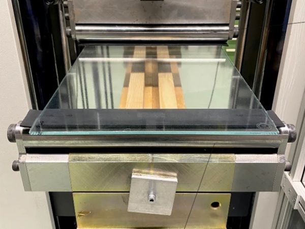
A prototype of the balustrade was produced in factory for approval and tested based on EN950: a) soft impact test releasing a sandbag of 50Kg to a height of 1,50m without damage; b) hardbody impact test releasing a metal ball of 4,5Kg up to height of 1,50m without damage; c) Postbreakage stability recording deflections of 3mm when breaking first glass panel and 5mm after breaking second glass panel outstanding his selfweight and stability for more than 10 days.
Site Installation
The assembly methodology on site had different phases, the order of operations being as follows:
1. Implementing the embedded steel plates
2. Assembly metallic posts
3. Assembly bottom shoe interior and exterior parts
4. Glass assembly
5. Assembly of superior stainless steel plates, interior and exterior parts
6. Sealing and finishing

Posts were installed with 8xM24 chemical anchor and filled with RE500 Hilti epoxy. The embedded steel plates were placed incast concrete accordingly to model and the bottom shoe installed with M8 rod and deviations of implantation of no more than 10 mm in all the threedimensional directions.
The glass was installed through the drawer/ cavity space of the bottom shoe placed in Nylon bearing blocks attached to VHB tape and fixed around the notches on the top plates. The gap between bottom shoe and glass was filled with a 15x8mm structural silicone DC895. The superior plates gaps were filled with structural silicone DC895 and finished with weather seal 10mm silicone DC791.

Acknowledgments
The work was done by Pentagonal with local partner Zapitis and the involvement and acknowledgment of among others Zaha Hadid Studio, Eckersley O Callaghan Engineers, Hyperstatic, Cricursa, Seveme and LOIS Builders.


