Date: 28 February 2018
In this process, a homogeneous distribution of the stress across the glass surface is of vital importance for the fracture pattern to be achieved and the flawless visual quality. Read here how the test is now also possible without destroying the glass in the test.
In relation to know-how and the manufacturable equalities of glass, German glass processors and finishers are world leaders, exporting large quantities of finished glass abroad. Since September 2015, the Vitro-DUR GmbH has been developing an online method for quality assurance in the current research programme “Glassy glass” funded by the BMWi-ZIM (Federal Ministry for Economic Affairs and Energy – Central Innovation Programme for SMEs) together with Softsolution GmbH in cooperation with the RWTH Aachen University and the University of Applied Sciences Munich.

In annealed glass, the light spreads uniformly in all directions. If stresses occur in the glass, the substrate becomes a birefringent medium. With tempered safety glass (TSG) and semi-tempered glass (STG), the heating of the substrate to over 600 °C and final rapid cooling results in compressive stresses becoming trapped on the surface of the glass and tensile stresses within the glass. Since glass is a poor heat conductor, the temperatures at the corners and edges are reduced more quickly than on the surface in the cooling process. The thicker the glass, the more pronounced this effect. The glass also cools down faster directly under the air nozzles. As a result, absolutely identical compressive stresses at each point distributed cross the surface are not achieved.

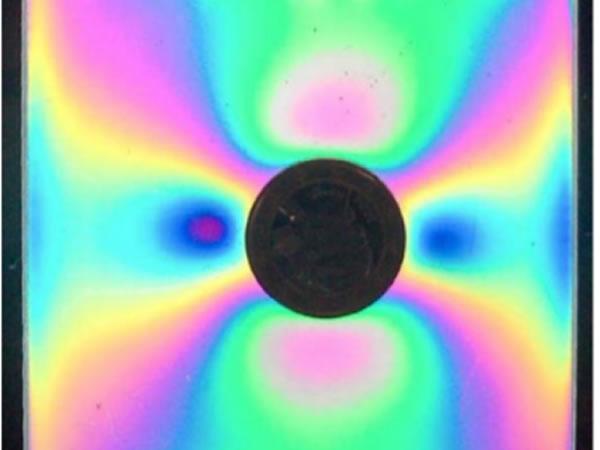
If light is passed through a glass under stress, then different changes in direction (depending on the wavelength) result in the glass mass. The light waves emerge from the glass with a certain delay, i.e. offset to each other. If the light is polarised by natural or artificial factors, these delays become visible as grey or coloured spots or striped patterns. These so-called irisations (Figure 01) are the direct result of stresses in the glass and are referred to as anisotropies. The more non-uniform the distribution of the trapped stresses, the more strongly pronounced are the anisotropies and the irisations identifiable under polarised light.
In visible sunlight, these consist of electromagne tic waves of differing wavelengths in the frequency range from 380 to 780 nm. The waves propagate randomly distributed in all spatial directions oscillating transversely away from the sun. For the purposes of simplification, the propagation of the individual wavelengths of the light can be imagined as sinus waves.
An artificial polarisation of the light is achieved by the use of so-called polarisation filters, which only allow light with a single, defined direction of oscillation to pass through. The design and selection of these (and other) optical devices have a significant influence on the resulting anisotropy image and its use in an analysis procedure. In a natural environment, it is even possible for light to be polarised in the earth’s atmosphere without optical devices – depending on the location, position of the sun and the weather conditions. Furthermore, polarisation can be achieved by reflection from media, such as water and glass. The analysis procedure presented here takes ...
Processing quality assurance
As part of the factory production control process, the product standards for TSG und STG prescribe both a continuous testing of the breaking stresses and evaluation of the fracture structure for each type and thickness of glass, based on an appropriate sampling plan. Although the product standard also optionally mentions suitable optical methods for determining the trapped stresses, no practicable non-destructive methods exist to date. For this reason, glass panes are in practice specially manufactured several times a day and then destroyed to test the quality achieved.
The product quality, however, is also dependent to a high degree on the processing, the format and the individual dimensions of the panes. With the samplings taken, it is only possible to estimate the visual quality achieved of the panes differing from the samples using existing methods. These are mostly based on the experience of the person in charge of the oven. By objective measurements of the delays, in contrast, it is possible to record the differences in stress trapped on the glass surface and – as far as technically possible in the plant – minimise them. This newly developed measuring method is thus able to ensure a reproducible quality for all formats and dimensions.
As an additional benefit, this is intended to increase the efficiency of the production processes and factory monitoring. If during production, the stress differences should turn out to be too large, say, by a change in external influences, then this should be immediately detectable and the process parameters accordingly adapted.

New measurement method provides a remedy
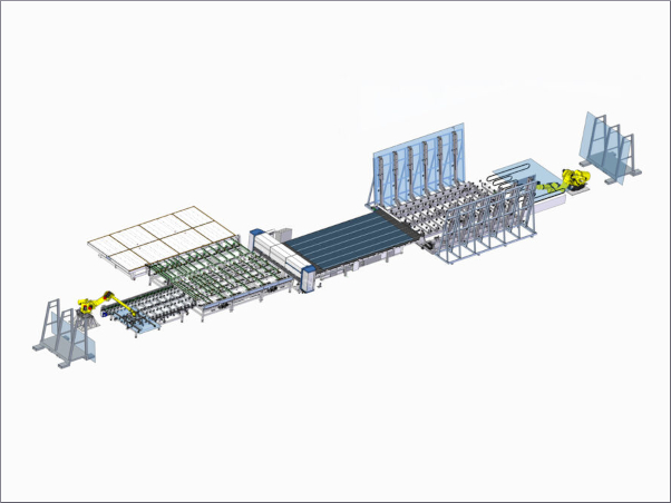
The aim of this research result is to obtain a method of quantifiably measuring the anisotropies in the glass surface and applying it in an online measuring system. Various research projects have shown that the non-destructive testing method of polarisation optics (Figure 02) acting on a surface is suitable for an objective evaluation, since it results in quantitative measurements.
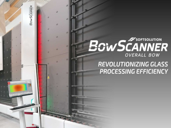
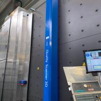
The method developed consists of passing the previously thermally tempered glass panes though a scanner, which records the anisotropy within the pane by using polarised light. As a result, areas within a pane exhibiting high anisotropy can be minimized by adjusting and calibrating the production-related factors in the tempering process. The specially developed scanner (Figure 03) has, in principle, the same construction as a polariscope.
To generate polarising filter recordings of thermally tempered glass panes, the scanner possesses light-sensitive line sensors as well as telecentric light modules. The light modules are equipped with a special polariser foil (polychromatic light), as depicted in Figure 04, Item 1, and the sensors with a matching analyser foil (Figure 04, Item 2), thus providing the ideal construction of a typical polariscope. The special feature of the design is firstly the modular structure typical for Softsolution, allowing a scanning range up to a total width of 4,800 mm, and secondly, in the telecentric lighting technology also typical for Softsolution.»
THE RESEARCH PARTNERS:
RWTH Aachen, Prof. Dr.-Ing. Markus Feldmann, Institute for Steel Construction; employees: Pietro Di Biase, Dr.- Ing. Ruth Kasper, Benjamin Schaaf University of Applied Sciences Munich, Prof. Dr.-Ing. Christian Schuler, Laboratory for Steel and Light Metal Construction, employees: Steffen Dix Construction and Software Development: Softsolution GmbH, Thomas Schuller, Hermann Sonnleitner, Andreas Hammerschmidt VitroDUR GmbHGlass Manufacturers, Uwe Bergmann / Thomas Fiedler (Uniglas GmbH)
The benefits provided by telecentric lighting and the associated incidence of light, which is always normal to the surface of the plane, are also undisputed here. This enables dead angles, which lead to problems when evaluating the edge membrane stress – particularly in the edge area, to be 100 % avoided.
Due to the precise 90° constant angle across the entire inspection width, the path taken by the polarised light through the glass body undergoing testing is always the same length. This ensures that there is no distortion to the result of the evaluation, which is based on the delay of the light. The imaging system is connected to (amongst other things) a speed-measuring incremental rotary encoder, which records the current transport speed and creates an overall picture from the individually recorded image lines. Different transport speeds can thus be compensated. The polarising filter recording thereby generated with a resolution of up to 400 x 400 dpi is then evaluated using software and pixel-accurately analyzed in relation to the height and distribution of the anisotropy across the pane. The scanner has already been successfully implemented in the production process of thermally tempered glass products. This enables a statement on the stress distribution to be made within seconds. The next step consists of the evaluation with product specific boundary conditions having an influence on the anisotropy.
The definition of threshold values is intended to allow a timely reduction in the stress differences visualized by means of corrective adjustments within the production process.
Steffen Dix, Thomas Fiedler, Benjamin
Schaaf, Hermann Sonnleitner
 600450






Add new comment