Article Information
- Digital Object Identifier (DOI): 10.47982/cgc.9. 546
- Published by Challenging Glass, on behalf of the author(s), at Stichting OpenAccess.
- Published as part of the peer-reviewed Challenging Glass Conference Proceedings, Volume 9, June 2024, 10.47982/cgc.9
- Editors: Christian Louter, Freek Bos & Jan Belis
- This work is licensed under a Creative Commons Attribution 4.0 International (CC BY 4.0) license.
- Copyright © 2024 with the author(s)
Authors:
- Jordi Alcaine - Arup
- Ed Forwood - Forwood Facades
- Pedro Gálvez - Sika
- Peter Lenk- - Arup
- Ulli Mueller - Sika
- Viviana Nardini - Sika
Abstract
In Structural Silicone Glazing (SSG) when applied to unitised curtain wall systems typical practice incorporates a pair of dead load plates intended to carry the glass self-weight and so avoid subjecting structural silicone to permanent shear. However in reality, due to the fabrication sequence and system behaviour some loads can occur which will be resisted permanently by the structural silicone. In a hung and sworded system (H&S), designers typically assume that slab deflection, or inter-story drift will cause a unitised panel to lift off from one support and so change the load path within it. To conform with this new load path, shear deformation will occur in the SSG joints. The deformation in the SSG joint will be permanent unless the supporting main structure returns to its original position. The structural performance of SSG joints subjected to permanent shear deformation in combination with short term loads is not adequately covered by any guidance. The aim of this paper is to provide a better understanding of the effect of the permanent shear deformation on SSG joints. Experimental tensile and shear testing has been carried out by Sika on H-specimens (Sikasil® SG-500) while imposing prescribed levels of shear deformation in combination with different accelerated aging conditions. The testing procedure, results and main conclusions are explained and summarised.
1.Introduction to structural silicone glazing systems
Originating in 1965, Structural silicone glazing (SSG) has been used in the building industry for nearly six decades. SSG revolutionized contemporary architecture by enabling the realization of the architectural aspiration for a seamless glass façade. Beyond its aesthetic appeal, SSG offers tangible benefits in terms of enhanced thermal efficiency, acoustics, and security, including improved blast andmanual attack resistance.
Structural glazing systems in façade engineering applications use a structural silicone adhesive to attach glass units to metal frames (typically aluminum) or to bond two pieces of glass together. The structural silicone joints then need to be designed to ensure that dynamic loads (i.e. wind, barrier) and permanent loads (i.e. self-weight) can be transferred safely from the glass to the structure of the building via the structural sealant and framing system.
The adoption of SSG presents significant challenges in terms of quality assurance and quality control (QA/QC) to ensure that the adhesive has adequate performance and fill. The use of structural silicone is therefore more widespread in unitized facades, where the glass is bonded and the silicone cured in the controlled environment of a factory and where external factors such as dust, temperature, moisture and relative humidity can be more readily controlled and monitored. SSG manufacturers provide specific and detailed procedures and recommendations that must be followed to enable correct adhesion, curing and joint fill.
Factory bonding is not however always practical, and designers should therefore also consider the implications of site applied SSG following for example an accidental glass breakage as well as the implications of site applied SSG for cyclical glass replacement. They should also consider the impacton eventual façade disassembly and system, component or material recovery requirements at the end of a façade’s lifespan to support a circular economy.
There are two main families of unitised curtain wall designs, i) hung and sworded (H&S) and ii) hung and hung systems (H&H). A hung and sworded unitised panel system is one that is typically hung from two brackets and constrained by spigots or swords into the panel below. The interlocking spigots provide both an out-of-plane and in-plane restraint with the latter restraint causing the panel to lift off one of its upper brackets in the case of inter-story drift of edge beam sag. A change of load path occurs when a panel lifts off and additional forces within the curtain wall unit arise. A hung and hung unitised panel by contrast does not have an in-plane constraint. The lack of constraint means that the mullion to mullion joints will open and close as a result of beam sag and means that a translation movement should be allowed for in the system stack joints in the case of inter-story drift.
2. Design of SSG in accordance with EOTA ETAG002
In Europe, international guideline EOTA ETAG002 provides simplified design recommendations for SSG joints bonding glass panels to metallic framing.
This document provides calculation methods for flat vertical glass of rectangular shape, bonded along all sides to load bearing profiles, restricted to limited deflections, and subjected to wind load, dead load and temperature variations.
EOTA ETAG 002 defines the design strengths according to the following safety concepts:
Design tensile strength - dynamic
![]()
Deign shear strength - dynamic
![]()
Desing shear strength - static
![]()
With:
- 𝑅𝑈,5𝑇 : Characteristic strength giving 75% confidence that 95% of the results from tensile tests of H-samples will be higher,
- 𝑅𝑈,5𝑆 : Characteristic strength giving 75% confidence that 95% of the results from shear tests of H-samples will be higher,
- 𝛾𝑡o𝑡=6 : Total safety factor for dynamic strength*
- 𝛾∞≥60 : Total safety factor for static strength, limiting creep effects.
Noting:
- a reduction to 4 can be used if advanced analysis is used but we note that this approach is not covered under EOTA ETAG002.
EOTA ETAG002 section 4.4.3 also states that “Building movements shall be accommodated by design features in the facade. It is essential to protect the structural seal from stresses resulting from building movements”.
It is apparent that hung and sworded systems (H&S) in contrast to hung and hung systems (both explained in more detail later in this paper) do not strictly adhere to this last principle. At the same time, it is recognised that these have been successfully used in numerous projects worldwide. The architectural desire to use wider panels with an associated thicker glass build up and having greater movements concentrated in the joints between the glass and frame when supported in a full one-bracket mode has led the authors to conclude that greater guidance is needed to confidently design and specify SSG joints in these systems.
New calculation methods (e.g. Advanced Calculation Method for Design of SSG Joints – Beyond ETAG002 by Vivana Nardini et al. 2019), design requirements and performance limits need to capture the real complex behaviour of SSG systems to enable designers to respond to the evolving market practice without any compromise on safety.
3. Architectural and construction drivers
In the last few decades, available technologies have developed considerably in the façade industry, increasing the complexity of projects and challenging the design of SSG joints applied in new system configurations and load conditions or combinations.
When designing structurally glazed unitized systems, the traditional strategy to ensure that building movements do not impose permanent movement to SSG joints in compliance with EOTA ETAG002 guidance has been to require very low deflection limits to the building structure, to limit panel widths or to use hung and hung systems.
As building-structure engineers rightly seek to minimize the embodied carbon of primary structures(with potentially lower stiffness) and architects push for wider units with minimal mullion dimensions, façade engineers, when opting for a hung and sworded (H&S) façade strategy, need to fully understand the implications of these drivers on the detailed design of SSG joints to provide an appropriate level of safety. The authors believe that façade engineers should seek to fully understand the demands placed on the structural silicone and the material’s ability to respond to those demands.
As illustrated in the diagrams below, the hung and sworded system (H&S) shown on the left has particular advantages when compared to a hung and hung system shown on the right with regards to mullion to mullion joint movements and building corner movement compatibility while posing particular challenges to the silicone joints between frame and glazing and the stack joint detailing.
Figure 1 shows a close up of the four way joint in a unitised curtain wall system with the upper panels omitted for clarity. The spigot detail that restrains the panel above can be seen in the hung and sworded system to the left.
Figure 2 shows how a bay of panels would respond to the vertical deflection of a simply supported beam. Note how the hung and sworded system lifts off one bracket connection while the hung and hung system results in the opening of panel to panel joints. (Note that the deformation is exaggerated in this view to aid understanding).
Figure 3 shows the impact of panel count on the relative movement of individual joints. Note how a reduction in panels typically implies greater movement in each of the remaining joints.
Figure 4 shows the impact of beam sag in combination with inter-story drift. Note how the combination increases the panel lift off for some panels in the hung and sworded system whilst reducing the lift off for others.
Figure 5 shows how a lower panel count in combination with beam sag and inter-storey drift is particularly significant to panel lift off and a potential worst-case scenario for system design.
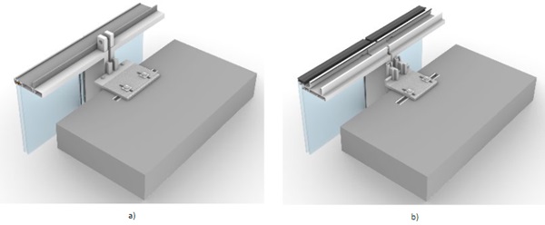


In the hung and sworded (H&S) approach solution, opening movements are concentrated in the stack joint between panels and less apparent in the mullion to mullion joints which predominantly experience shearing movements. The steps between panels tend to impose a flex on the shelf gasket between units and it is recommended that guidance should be sought from system providers on reasonable limits and whether a wider mullion to mullion joint is needed for larger step movements.
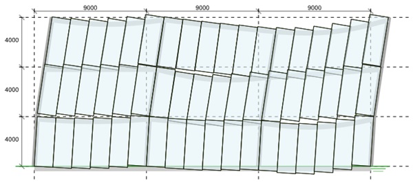
As can be inferred from figure 6 below a full system design should anticipate many potential combinations of movements and size the joints between panels accordingly. In the diagram below the deformations are exaggerated to aid understanding. In the design of unitized panels, it is important to ensure that all of the joints can accommodate the expected movements without any panel to panel pounding or hard contact.
4. Real behaviour of structural silicone glazed systems
4.1. Structural behaviour of SSG systems under gravity loading
As a result of the typical fabrication sequence with silicone applied to panels in a horizontal state prior to rotation to their final vertical orientation, the dead load of the glass panel is, in reality, shared between SSG and the supporting ‘dead-load’ plates. The exact distribution will vary depending upon the stiffness of the silicone, the stiffness of the plate detail, the stiffness of the frame and the initial tightness of fit of the glass to the plate support detail.
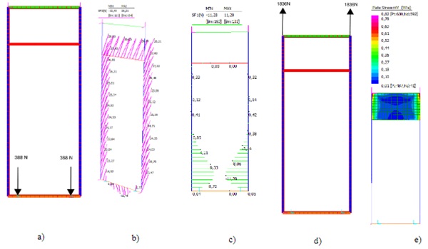
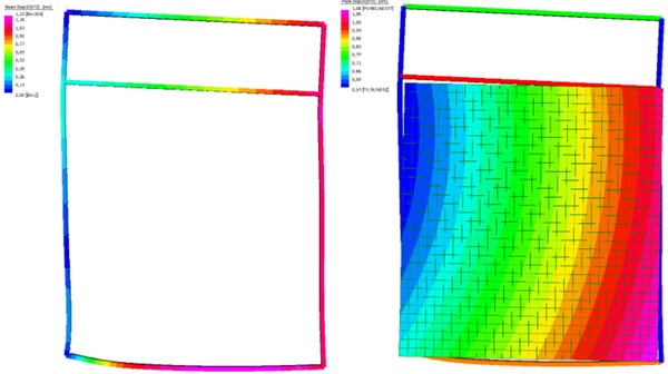
As shown by the analysis illustrated in Figure 7 the effect of these permanent stresses on the silicone cannot be neglected and should arguably be accounted for during the design phase in combination with other actions (e.g. slab deflection, inter-storey drift and out of plane wind load).
When initially installed, the vertical deflection of the transom will result in some inward bowing of the mullions (i.e. bending on the mullion’s weak or minor axis) and this will, in turn, result in some in plane stresses within the silicone along the mullion profile. It will also affect the vertical in-plane stress in the silicone to the transoms both at the top and bottom of the glass unit.
The diagrams in Figure 7 below are taken from a project study of a hung and sworded (H&S) panel when the panel is evenly supported from both brackets from Structural Silicone – Design & Modelling. (Alcaine et al. 2020). The analysis model included beam elements for the mullions and transoms, spring elements for the silicone (idealised as a series of discrete elements spaced evenly around the glass panel), plate elements for the glass (not shown in the diagrams) and plate elements for an aluminium spandrel. Figure 7b shows the vertical shear forces in the silicone vary around the profile and how the sag of the lower transom impacts on the magnitude of force across the transom. Figure 7c shows how the in-plane, minor axis bending of the mullions has an impact on the magnitude of horizontal shear forces in the silicone.
4.2. Structure/ façade interaction (movement accommodation) and influence on SSG
It is often assumed that hung and sworded systems (H&S), after panel installation, hang evenly off both brackets, and that under building movements (including slab edge deflection and building sway) panels instantly lift off from one bracket and so exist in either a uniform two bracket or a rigid one bracket mode. This idealized assumption is a useful simplification in developing movement accommodation calculations with unit panels considered as rigid bodies and with no deformation considered internally at the panel level between the glass and the idealized rigid rectangular framing unit.
At an individual panel level though the reality is more complex. I n panels that are detailed as hung and sworded (H&S) increasing slab deflection will tend to result in progressive panel racking deformations until a critical limit is reached when the panel will finally lift off from one bracket, with the dead load eccentricity then stabilized by an interlocking “sword”. In order to provide a valid load path, the structural silicone will need to transfer the dead load eccentricity of the glass to the frame imposing a shear deformation (strain) on the SSG joints and various bending moments onto the framing elements themselves.
The strain state experienced by the SSG joints will be permanent unless the stress is high enough to cause progressive creep or unless the deflections causing the strain state reverse (e.g. live load that comes and then goes).
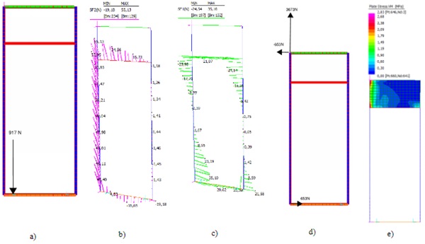
The diagrams below are taken from a project study of a hung and sworded (H&S) panel under the “one bracket mode” included on Structural Silicone Glazing – Design & Modelling (Alcaine et al. 2020). It can be seen how the change in support conditions, with the associated change in load path within the panel has a particular impact on the vertical and horizontal shear forces in the discrete spring elements used to model the silicone (8b and 8c).
An idealised sequence of support states between a uniform two bracket mode through a transition to a fully lifted, one bracket mode in SSG hung and sworded (H&S) systems is illustrated in the diagrams below:
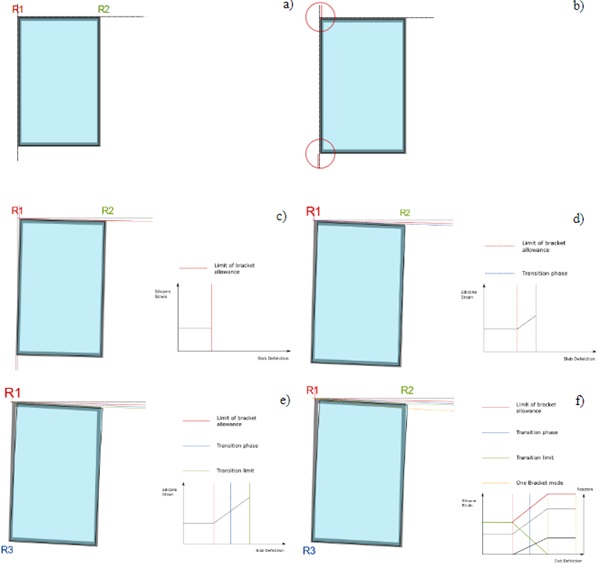
Where panels are in a full one bracket mode, if the silicone stress is high, creep movement in the silicone may occur together with some associated load redistribution and additional frame deformation. This additional frame deformation may even make the panel touch down again into a two bracket transition state with both of the upper brackets taking some load. It can be concluded that under this scenario silicone stresses may then reduce and creep movements/silicone strains be arrested. The out of plane capacity of the silicone under the final equilibrium position is however important and explored further in this paper It is recommended that curtain wall engineers only consider slab or edge beam deflections that occur after panel installation (e.g. live load, superimposed dead load, creep) and critically review what combinations of loading are commensurate with the factors of safety applied to silicone design. It is recommended that within that review the duration of load should also be considered. It is hoped that in due course further industry guidance will emerge to define appropriate load combinations with reasonable load factors.
4.3. Wide panels and the roles of structural silicone in a hung and sworded (H&S) approach
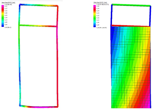
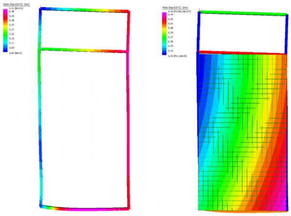
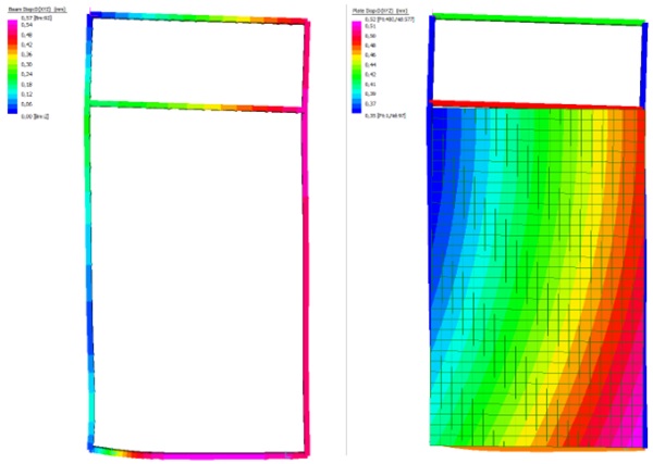
The importance of the difference between the idealized behaviour (the panels are rigid bodies) and the real behaviour (as hypothesised in figure 9 and shown in figure 10) becomes more significant where façade panels become wider or where the structural silicone joint detailed is minimised (and therefore becomes less stiff and efficient at maintaining panel rigidity).
The diagram below in figure 10 highlights potential variations in the deformation characteristics of units of 1.5, 1.8, 2.0 and 3m widths based upon a 4m height when supported in a hung and sworded (or one bracket) mode. The images are all produced with the same level of deformation magnification and illustrate how the movement between glass and frame (and the associated silicone shear) increases with panel width. It is recommended that the level of silicone shear be quantified and discussed with the silicone provider to ensure that the supplier’s design limits are respected.
4.4. The role of structural silicone glazing (SSG)
As structural engineers seek to minimise the embodied carbon of edge beams and architectural practice continues to push for wider units with minimal mullion to mullion joints, the scenario where slab deflections reach the limit of the transition mode forcing panels into a full one bracket mode and imposing larger shear deformation (strain) on the SSG joints is likely to become more common. It is also likely that building structure engineers will also seek to reduce embodied carbon in a building’sstability system making them more flexible and increasing the tendency of panels to fully lift off in a building sway event. Silicone joints must resist out of plane wind load at the same time as these events.
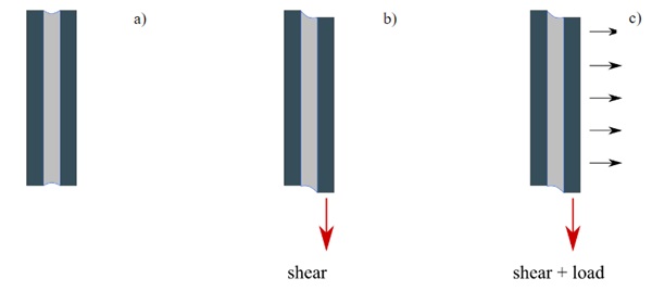
The structural behaviour of structural silicone in resisting out of plane loads (e.g. wind) when subjected to shear deformation in this way is not well documented, besides is not covered by ETAG002 as stated in section 2 and previously discussed.
While some guidance is available (e.g. Advanced Calculation Method for Design of SSG Joints – Beyond ETAG002 by Vivana Nardini et al. 2019 and Structural Silicone Glazing – Design and Modelling by Alcaine, Lenk and Forwood.2020) the lack of ETAG guidance where permanent strains become more significant can put suppliers into a difficult position in providing warranties for wider panel units in the hung and sworded (H&S) configuration and may make designers more nervous of taking responsibility for a hung and sworded (H&S) approach. While there is general confidence in the design of units with high aspect ratios (AR = height/width), confidence might diminish for wider units with lower aspect ratios.
To our knowledge, there has not been existing testing data available (nor testing protocols) to assess the effect of permanent shear deformation on SSG joints when subjected to tensile or shear loads. In our opinion, there is a need for the industry to have a better understanding on the complex behaviorof SSG systems, and to do so, it is essential to understand the effect of permanent shear deformation on SSG joints with regards to any reduction in their tensile capacity.
To understand this combined effect (permanent shear + dynamic tensile and permanent shear + dynamic shear), new experimental tensile and shear testing procedures have been developed for this research to test Sikasil® SG-500 H-specimens while imposing varying deformation levels.
This development is of importance to the current and future procurement of unitised structural silicone glazed unitized systems as Specialist Façade Contractors rely upon both an understanding of the total structural behaviour of the facade panels (frame + glass + silicone) and warranties provided for the structural silicone.
5. Test investigation
In order to investigate the impact of permanent shear displacements on SSG joints superimposed by dynamic tensile or shear loads, an advanced testing protocol was discussed amongst the paper authors and then established and performed by Sika using Sikasil® SG-500 adhesive. Beyond Standards and known practices, the new test concepts were developed producing innovative H-specimens with joints 12 mm x 12 mm x 50 mm (bite x thickness x length) bonded on aluminum substrates, ensuring always 100% adhesion. 180 samples were produced and tested as follows:
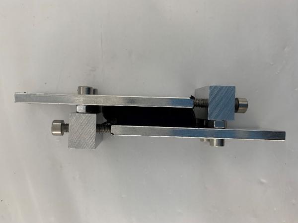
- 90 samples, as shown in Fig. 15, were produced and cured for 28 days at 23 °C / 50 % r.h.. Samples were then exposed to different levels of shear displacement: 0 mm, 1 mm, 2 mm and 3 mm.
Samples were simultaneously exposed to different storage conditions:
-Storage A: 7 days at 23 °C / 50 % r.h.
-Storage B: 7 days in water immersion at 23 °C
-Storage C: 6 weeks in water immersion at 45 °C
-Storage D: 91 days at 23 °C / 50 % r.h.
When storage conditioning was completed, the samples were tested in tension without releasing the joints from the imposed shear displacements (Fig. 15). In other words, tensile tests were carried out with the shear displacement still imposed, to simulate real joint conditions in façade applications (e.g. concurrent wind load and permanent slab deflections causing a shear deformation on the SSG joint). - 90 samples as shown in Fig. 16 were produced and cured for 28 days at 23 °C / 50 % r.h.. Samples were then exposed to different levels of shear displacement: 0 mm, 1 mm, 2 mm and 3 mm.Samples were simultaneously exposed to the storage conditions A, B, C and D described above. When storage conditioning was completed, the samples were tested in shear without releasing the joints from the shear displacements imposed (Fig. 16). In other words, shear tests were performed with the shear displacement still imposed, to simulate real joint conditions in façade applications (e.g. concurrent thermal dilatations and permanent slab deflections).
Both the joint dimensions selected, and the accelerated aging conditions implemented refer to the ones defined by either EOTA ETAG 002 or ASTM C1135 and ASTM C1184 to assess product performance and strengths by testing H-specimens. The speed of 5 mm/min was used in both tensile and shear tests described above, as per EOTA ETAG 002 requirements. For each storage condition and shear displacement level imposed, at least 5 samples were tested.
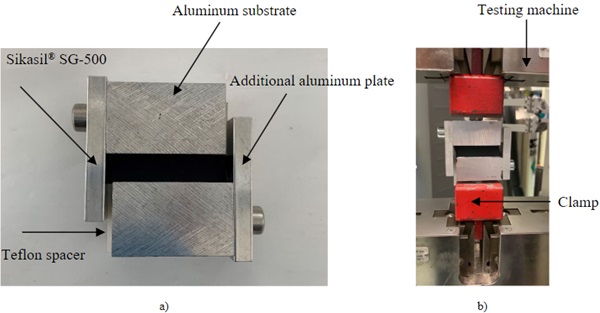
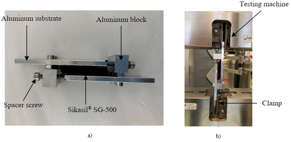
Table 1 summarizes the test results obtained when no shear deformation was imposed and the samples were just tested in tension after storage A - D. Results are provided with reference to the percentual change of ultimate strength, calculated as follows:
![]()
With:
σStor_i= average ultimate tensile strength after Storage i
σRef= average reference ultimate tensile strength (test after curing – Column 1 of Table 1)
Table 1: Ratios σStor_i/ σRef [%].

Table 2 summarizes the tensile test results obtained when different level of shear displacements wereimposed to the samples simultaneously conditioned in Storage A – D. For each storage i, results are provided with reference to the percentual change of ultimate strength, calculated as follows:
![]()
With:
σDispl_n,i= average ultimate tensile strength when shear displacement n is imposed and samples are exposed to storage i
σDispl_0,i = average ultimate tensile strength when no shear displacement (0 mm) is imposed and samples are exposed to storage i (row 1 of Table 2)
Therefore, each column of Table 2 provides results not linked to the ones provided in Table 1. Due to long conditioning, results of Storage D are not yet available. Only tensile test results are provided in this paper, focusing on imposed deformation + wind load case.
Table 2: Ratios σDispl_n,i / σDispl_0,i [%].

5.1. Test results summary and conclusions
- Results show that imposing a permanent shear displacement to SSG joints does reduce its ultimate strength: the higher the deformation imposed, the greater the reduction.
- Storage C represents the most demanding aging condition, although storage D is also expected to be demanding.
- In SSG joint design, additional safety margins are needed to account for the scenario of building movements and slab deflections cause permanent shear deformations within the structural silicone.
5.2. Next steps
Further investigation is required to fully explore the impact of shear displacements on SSG joint behavior. Among others, following steps should focus on:
- Test investigation on different joint dimensions, more representative of real applications,
- Evaluation of shear displacements imposed, which can be either permanent or dynamic,
- Investigation about combined aging C and D,
- Evaluation of strength variations based on analysis of data from multiple adhesive batches.
6. Conclusions
- Additional testing is needed to fully explore a range of imposed strain states with different silicone joint aspect ratios and with applied tensile testing,
- The impact of ageing on performance needs to be further studied and reported,
- There does appear to be a reduction in tensile capacity for an increase in silicone shear state,
- Recommendations for modelling approaches to investigate the actual behaviour of SSG, panels calibrated against full scale panels supported under a one bracket mode are needed,
- Recommendations from suppliers for simplified rules for narrower panels would be helpful,
- Recommendations for enhanced modelling approaches for wider panels to justify adoption of lower factors of safety (e.g. 4 rather than 6) would be helpful,
- Façade Engineers will need to respond to holistic project level drivers to reduce the embodied carbon of buildings by investigating the impact of more flexible edge beams and more flexible main structure stability systems and in the interests of sustainable practice and not to insist on more carbon-intensive stiffer supporting structures. They will need to communicate physical constraints to their collaborators to provide façade systems with appropriate levels of safety.
Acknowledgements
We would like to express our sincere gratitude to all those who have contributed to the development and completion of this paper and to Arup and Sika for their support and resources that made this research possible.
Last but not least, we express our profound gratitude to the organizers of the Challenging Glass 9 conference for providing a platform to share our findings, allowing us to raise awareness of the topicto the wider industry and provide the opportunity to engage with fellow designers, engineers and researchers in the field.
References
Alcaine, J., Lenk, P. Forwood, E.: Structural Silicone Glazing – Design & Modelling. Challenging Glasss 7. https://proceedings.challengingglass.com/index.php/cgc/article/view/333 ;(2020).
EOTA – European Organisation for Technical Approvals - ETAG 002., Guideline for European Technical Approval for Structural Sealant Glazing Kits (SSGK), European Organisation for Technical Approvals; (2012).
Nardini, V., Doebbel, F.: Advanced Calculation Method for Design of SSG joints – Beyond ETAG002. GPD; (2019).
Sika Services AG.: Design and calculation of SikasilⓇ SG joints in Structural Sealant Glazing applications; (2022).
Sika Services AG.: Additional technical information - SikasilⓇ SG – joint calculations; (2017).
The institution of Structural Engineers – Structural aspects of cladding; (2020).https://www.istructe.org/resources/guidance/structural-aspects-of-cladding/

