Article Information
- Digital Object Identifier (DOI): 10.47982/cgc.9.597
- Published by Challenging Glass, on behalf of the author(s), at Stichting OpenAccess.
- Published as part of the peer-reviewed Challenging Glass Conference Proceedings, Volume 9, June 2024, 10.47982/cgc.9
- Editors: Christian Louter, Freek Bos & Jan Belis
- This work is licensed under a Creative Commons Attribution 4.0 International (CC BY 4.0) license.
- Copyright © 2024 with the author(s)
Authors:
- Richard Green - Green Facades LLC
- Andrew Crosby - RJC Engineers

Abstract
Glass handrail loading and design in the United States lags behind best practice in other parts of the world. Improvements are possible for the design load, residual capacity and damage-event loading, each of which could be based on occupancy. Neither static loading nor impactor testing accounts for the dynamic effects of sustained loading to handrails during crowd load events. Alternate configurations for improved robustness at similar size and cost are presented.
1. Design Loads
In the United States glass balustrades are governed by IBC, ASCE/SEI 7 and ASTM E2358, with ASTM E2353, (although the ASTM standards are notable in their absence as referenced standards of IBC.) The code required maximum design loading can be loosely summarized as:
- a distributed load of 50 lb/ft (0.73 kN/m) (IBC 1607.8.1, ASCE 7, ASTM E2358),
- 200 lb (890 N) point load to the top rail, and
- use of laminated glass to prevent fall of glass to walkways below (IBC 2407.1.), however there is an exception for this rule if there is no walkway below or the walking surface is permanently protected from falling glass.
ASTM 2358 additionally has an impact load of up to 400 ft-lb (542J) via a lead shot bag.
Review of some of the available documentation found that changes in international standards appear to have been initiated around 1996 when the British Standards Institute introduced crowd loading in BS 6399. Historically, this follows the Hillsborough disaster in 1989 in which 96 people died in conditions of overcrowding following collapse of a crowd barrier at an FA Cup semi-final soccer match. Extensive investigations of the event as reported by R.A. Smith “The Hillsborough Football Disaster: Stress Analysis and Design Codes for Crush Barriers” found loads of up to 8 kN/m caused the failure of the barriers. However, unless extreme overcrowding is anticipated, 3kN/m has been recommended, with BS EN 1991 suggesting a range of 3kN/m to 5kN/m. Perhaps just as significantly, a load of 1.5 kN/m is also recommended for general assembly areas that are not subject to overcrowding.
Wikipedia (https://en.wikipedia.org/wiki/List_of_fatal_crowd_crushes#21st_century) includes a listing of some of the fatal crowd crush events, suggesting that these events are sufficiently frequent that they should be designed for. While it is not known if barriers collapsed in these events, it is known that when barriers fail it causes crowd collapse, which is likely to cause fatalities.
At the First International Conference on Engineering for Crowd Safety, focusing on the causes and prevention of crowd disasters Fruin, J.J. (1993) makes a connection between crowd crush and the levels of load that can be anticipated within the crowd and hence also to the barrier at the perimeter of the crowd.
Experimental Investigation of the human loadings on handrails and barriers by C T Styan, M J Masia & P W Kleeman (2007) concludes that the loadings in AS 1170.1 – 2002 (which are very similar to BS 6399-1996) are indeed reasonable, as well citing a number of failures that have been investigated.
We note that the ASTM for handrails E985 was not updated since 2000 and so has not had such loadings updated and neither have such loadings been introduced in ASCE7 or IBC. (The author has petitioned for changes at both organizations.) A survey, of national loading codes found that 42 of 45 had adopted crowd loading of some sort. The United States currently has the lowest maximum-balustrade-loading that has been found and the single level of loading is ½ of assembly loadings and ¼ of crowd loadings.
Given that glass is a brittle material, it is recommended that loadings follow international best practice. The proposed loads in take guidance from BS 6399-1996, EN 1991-1-1:2002, AS/NZS 1170.1-2002 (Australia/New Zealand), ABNT NBR 6120 (Brazil) and National Building Code of Canada 2015 when nominating loads for balustrades. However, when designing with brittle systems, such as glass, an appropriate initial load is only part of the design problem. Consideration of loads during and after the design event are both also important.
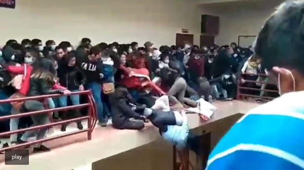
When observing video of brittle balustrade failures, such as the El Alto University Disaster in Bolivia, in which 7 students died, we see that crowd pressure initially forces multiple people off the unprotected precipice before they can pull back from the failed assembly. We can assume that similar continuity of force would accompany the brittle failure of a glass assembly and there may be a dynamic factor associated with the damage event.
This paper looks at design practices for glass balustrades, particularly where the glass is the structural element providing the primary restraint for the occupant.
2. Retention, Redundancy and Residual Capacity
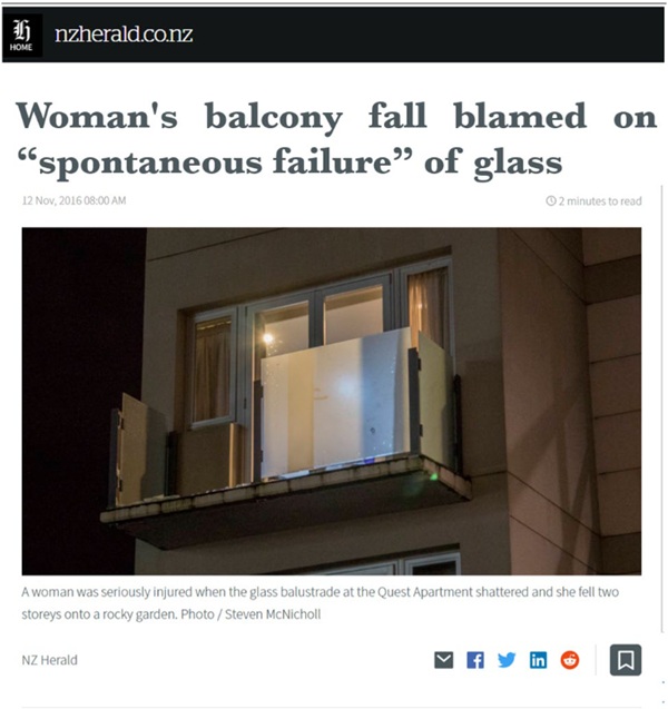
The requirement for laminated glass was introduced to IBC in 2015, after a series of glass balustrade failures occurred in Seattle, Toronto, Austin and elsewhere. There were a number of close calls; it was considered that sooner or later a fatality or serious injury was likely, and the code was revised to restrain falling glass. While guardrails are provided for a purpose -- to restrain people from falling off a precipice -- the retention of the glass provided only addresses part of the risk. A robust solution needs to consider retention, redundancy and residual capacity so that brittle materials continue to serve their purpose of preventing falls.
Australian Standard AS1288 addresses all aspects of robustness for balustrade glass. It has required lamination since 2006 and it introduced a requirement for residual capacity and stiffness in 2021.
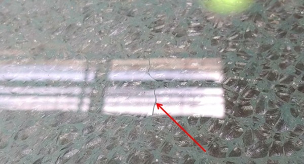
The primary risk addressed by lamination in the IBC is fall of glass due to spontaneous fracture, often due to Nickel Sulfide (NiS), however spontaneous fracture is not limited to the effects of NiS, as other inclusions and mounting system stresses can also participate. For an inclusion to cause fracture, its expansion must be significant and interact with a tension field to overcome the inherent tensile strength of the glass. Usually this means a ‘large’ NiS stone (<0.55 mm, typically 0.22mm) near the center of the glass in fully tempered glass. If the stone is not large or is not near the center it will not cause spontaneous fracture, but it will still expand and still has the capacity to weaken the glass.
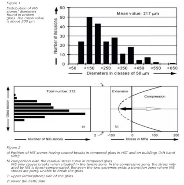
The distribution of inclusions throughout the thickness of the glass will be random. The size of NiS stones is somewhat random, but larger stones tend to fall to the bottom of the melt pot and not be included in the float. (Some settlement also appears to occur within the float.) For fracture to occur, growth of the inclusion needs to be in a tensile stress field. While stones outside the tension zone will not cause spontaneous fracture, either in practice or heat soak testing, it can interact with tension fields due to bending to reduce the capacity below design levels.
3. Fully Tempered (Toughened)– is it ‘Safety Glass’?
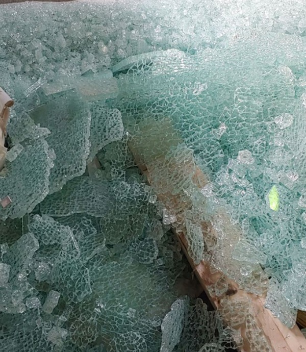
It is also important to understand that FT ‘safety glass’ does not always break into ‘harmless small dice’. The crack wave front is driven by tension stress; the tension is in the center of the glass, but the surface is in compression. The compression zone tends to remain as a ‘skin’ on the fractured glass, holding clumps together until the aggregate expansion of the wavefront causes tension or it impacts something hard – and if the ‘something hard’ happens to be a person, the outcome can be lethal.
Surface penetration of the crack wavefront is not the same as dicing within the tension zone, cracks may travel in the tension zone without severing the skin in the compression zone.
4. Glass Risk Categories and Robustness Requirements
CEN/TS 19100 goes part way to providing design guidance, incorporating the concepts of in-service loading during a fracture event and post-fracture analysis, but it does not (until part 4 is published) include what levels of residual capacity to use, or when to use them.
Part of the challenge is setting suitable design targets for different circumstances: just as live loads are based on occupancy or building risk categories, so robustness levels also need to be based on occupancy (both sides of the barrier), thus the importance of the concept of ‘glass risk categories’. A more general proposal for glass risk categories and robustness is included for context. (See also Structural Glass Design Manual - A Design Guide and Voluntary Specification for the Use of Glass as a Structural Material in Buildings, Green ,Crosby, McDonell (2024) at this conference.)
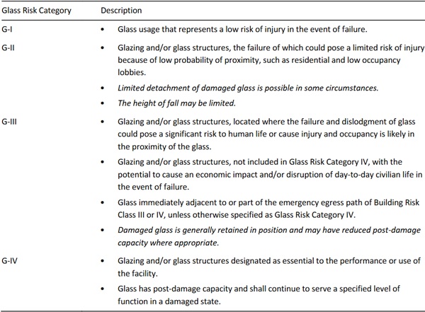
4.1. Proposed Glass Risk Categories
Table 1: Descriptions of Proposed Glass Risk Categories.
4.2. Proposal for Robust Design
Figure B.1 Flowchart - Robustness Requirements
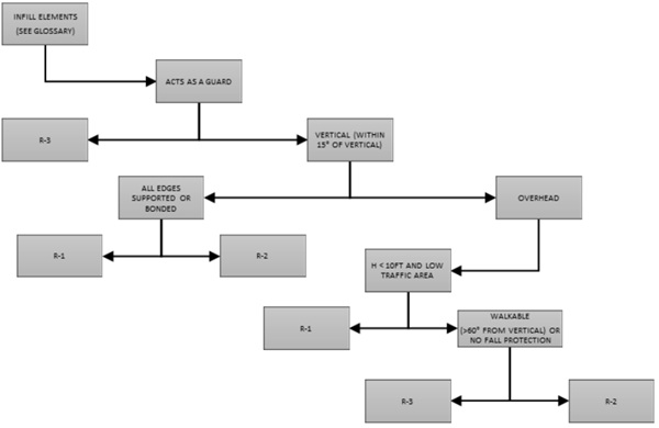
Table B 2 Robustness Requirements
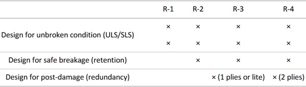
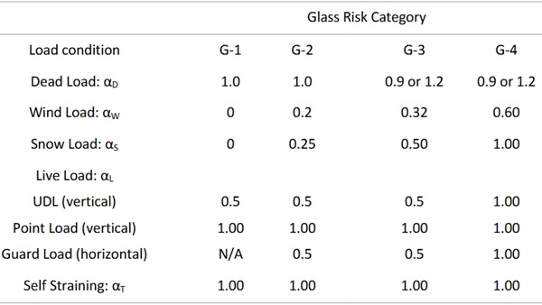
Table 1: Post-damage load factors proposed for a Structural Glass Design Manual.
Table B 5 Post-Damage Load Factors
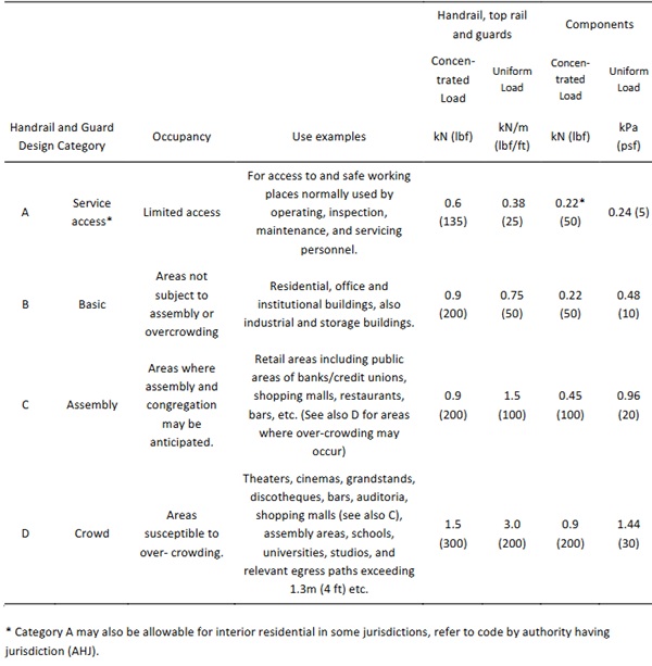
5. Proposed Design Loads for handrails
(Based on AS1170.1 and EN1991-1)
Table 2: Proposed Guard and Barrier Loading.
6. Reasons Why Robustness is Important by Occupancy
Residential: - G-II
Young children do not recognize the difference between a solid barrier they cannot see and a missing barrier they cannot see. In the case of spontaneous fracture resulting in a glass infill barrier leaving an opening, young children have failed to recognize the opening or risk and have fallen to their death. As such retention of barriers are recommended throughout.
Light Commercial: G-II
These applications are typically over walkways, despite lower occupancy and risk of injury and typically adult occupants, fall of glass is recommended to be prevented.
Assembly and Heavy Commercial: G-III
These applications are typically over walkways, hence fall of glass is required to be prevented.
Crowd – G-IV
In a crowd situation, there will be continued thrust from the crowd after the initial breakage. As such, the barrier needs to continue to provide restraint immediately following the loss of one ply to prevent sudden collapse of the barrier.
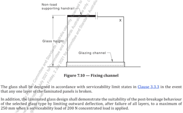
7. Design Practices
For structural glass balustrades, AS1288 requires laminated glass for fall heights greater than 5m for infill glass and lamination with residual capacity for systems where the glass is providing the structural restraint. With one ply broken, AS1288 requires residual capacity to resist serviceability loads (unfactored (ASD) load vs. ultimate design strength) with one ply broken. AS1288, since 2021, also requires testing for both plies broken with a maximum deflection of 250mm (10in) under a load of 200N (45lbf).
It should be noted that AS1288 references design loads from AS1170.1 (imposed loads/Live Loads) AS1170.2 (Wind Loads) and load combinations from AS170.0. The load factor for live load is 1.5, thus the design residual capacity load is 67% of the design load. The design load includes assembly loads of 1.5 kN/m (~100 lbf/ft) and crowd loads of 3.0 kN/m (~200 lbf/ft).
ASCE-7 Section 2.5 includes load combinations for ‘extraordinary events’. If the glass is well designed, well fabricated and well installed, then it should not break under design loads and the causation of breakage is likely due to some other extraordinary cause. This section includes two tests, during the damaging event and residual capacity. In both cases ASCE-7 has a load factor of 0.5 L as opposed to 1.6 L in the design situation, however during the damage event there is an additional load affect that must be accounted for.
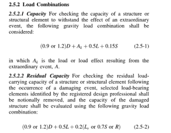
The ASCE 7 combination is 31.25% of the design live load (which is normally has a load factor of 1.6 for limit state design) but the sudden loss of stiffness due to breakage results in a dynamic effect for the component of stiffness loss. While the theoretical dynamic factor is 2.0, it is common in crane codes, etc. to use dynamic load factors of 1.8, making allowance for some damping.
Before looking into the implications of the continued load during the extreme event, consider the type of events that cause glass fracture in balustrades and whether load may be present.
Spontaneous Events – fracture without load application or fracture well below design loads.
Grab/Impact Load – the impact load which breaks the glass also stops the person and there is no sustained load. (G-II) Unlikely to have sustained load after initial impact load.
Assembly Loads – (G-III and G-IV) Possible continued thrust after damage event, but it is likely that there will be some recoil after the damage event and the load will decrease as the balustrade deflects away.
Crowd Loads – (G-IV) Potential/probable continued thrust from crowd after damage event and barrier is required to provide a safety function. Damage event calculation is highly recommended.
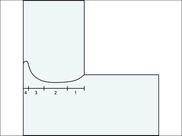
Examining some of the options, let us consider a hypothetical balustrade without top rail subject to assembly loads in a G-III environment with a load of 1.5 kN/m (~100 lbf/ft).
In the following example, we see that post-damage controls the design with one ply broken.
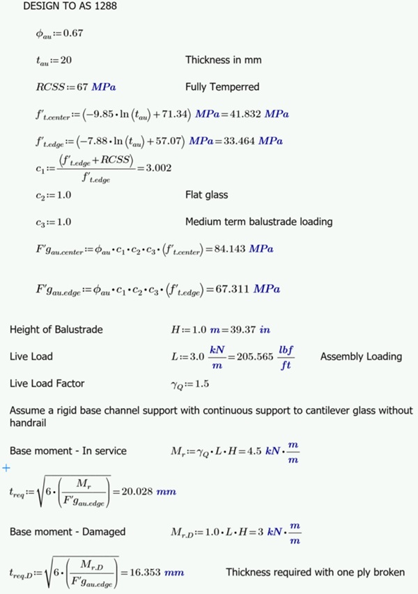
Thickness required after one ply broken is greater than half initial thickness – post-damage capacity controls.
If the logic of sustained load during the damage event is applied, breakage of the second lite is likely in assembly and crowd loading for 2 ply systems. Alternative design following extraordinary loads case, consistent with ASCE7, offers another option with superior outcomes. In this case the strength model is based on EN16612 and CEN/TS 19100.
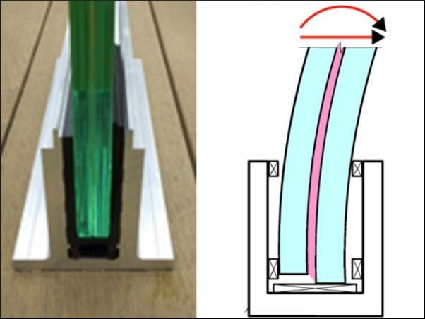
First look at the behavior of a 10mm+1.52mm+10mm 2-ply laminate with damage-event loading using the ASCE7 extraordinary loads case. (Nominal thickness is used for simplicity, actual calculations should use minimum thickness applicable to the location of fabrication (not installation.))
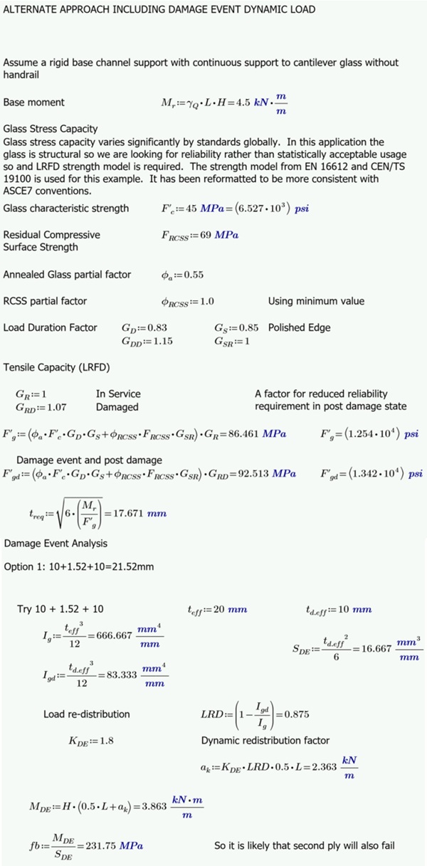
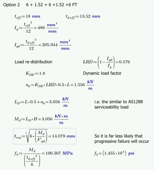
Consider an alternate configuration of 6mm + 1.52mm + 6mm + 1.52mm + 6mm (18mm glass, 21.04mm overall).
Note that glass with typical strength will not break under the design load and a weakened glass is likely to fracture before developing full load, hence the reduction in load during the damage event. Further, as the glass fractures and the balustrade deflects, there will be some recoil from the occupant and some release of load (crowds excepted.)
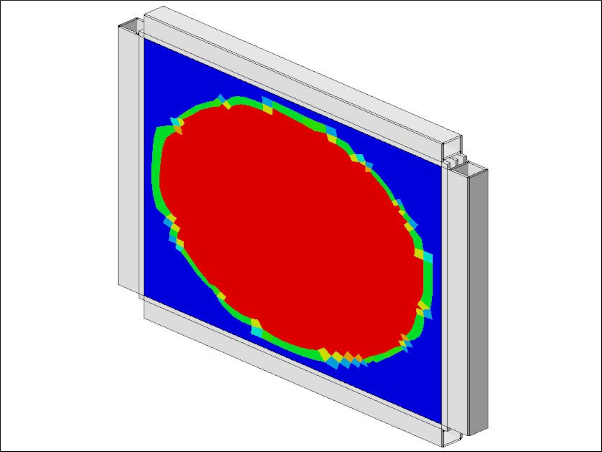
The residual capacity with the 3-ply system and the most critical ply broken is greater than a 2-ply system and the portion of the load that is dynamically redistributed is much less. As a consequence, it is far less likely that progressive failure of further lites would occur if the handrail was to fracture under load.
Should all plies fail, the stiffness of the interlayer becomes a critical aspect of the design. Typical PVBs were initially designed for car windscreens to absorb energy if a rock hit the glass and the extension of typical PVB allows the glass to fold over (there are some ‘structural PVBs’ that prevent this.) To resist this, AS1288 has proposed a residual capacity test of <250mm (10 in) deflection under a load of 0.2 kN (45 lbf) with all plies broken.
The use of a structural grade interlayer with a suitable stress-strain curve, combined with a 3-ply configuration, offers a much stiffer system with significant residual capacity.
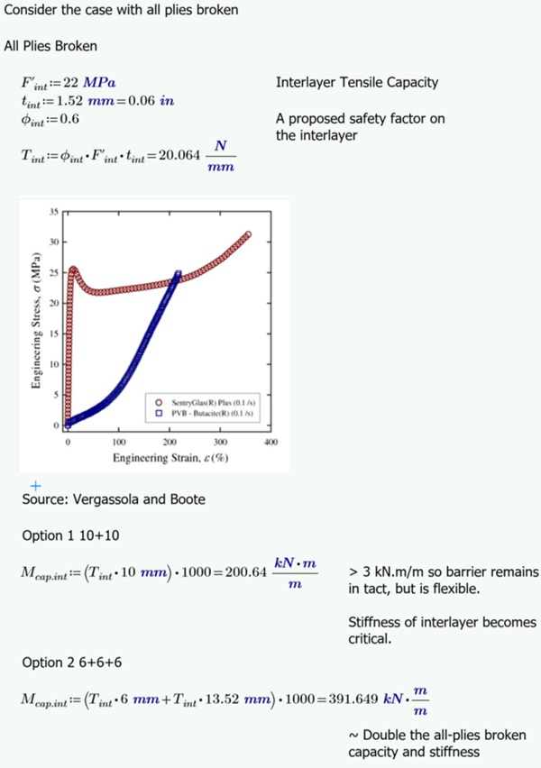
Interestingly, due to the cost efficiency of 6mm (1/4in) glass, a review of 6+6+6mm glass configuration with glass suppliers has indicated that, where lamination is already occurring, 3 plies of 6mm may be cheaper or similar cost relative to 2 plies of 10mm.
Taking this into consideration, adopting the principle of Extraordinary Events in ASCE-7 to glass balustrade design results in glass of similar thickness, similar cost and far superior robustness.
8. Conclusion
Global design practice for balustrades indicates that loads of 1.5kN/m (100 lbf/ft) are justified for assembly locations and 3kN/m (200 lbf/ft) for areas subject to crowd loading.
Glass may have rare imperfections or inclusions that reduce the capacity of the glass.
The design of glass balustrades (without structural handrails) should provide post-damage capacity and such practices are required by AS1288 and CEN/TS 19100. In another approach, considering extraordinary events per ASCE-7 and CEN/TS 19100 take into account the potential for load during a damage event, this study finds the critical event to be the dynamic damage event in cases of sustained crowd loading. This paper proposes that appropriate level of load during and after a damage event is a function of the occupancy.
A configuration of 3 plies of 6mm glass (6mm + 1.52mm+ 6mm+1.52mm+6mm=21.04mm) was found to be significantly more robust than 2 plies of 10mm (10mm+1.52+10mm = 21.52mm) forming a similar overall thickness but with far superior redundancy characteristics. Surveying manufacturers found that superior performance can be achieved without significant cost increase.
References
ABNT NBR 6120:2010 Norma Brasileira - Design Loads for Structures (translated)
AS1288:2021 – Australian Standard: Glass in buildings—Selection and installation, Standards Australia
AS/NZS 1170.1 – 2002 Structural design actions - Part 1: Permanent, imposed and other actions, Standards Australia
ASCE7 (ASCE/SEI 7) -2022 Minimum Design Loads and Associated Criteria for Buildings and Other Structures American Society of Civil Engineers
BS 6399-1: 1996 Loading for Buildings
BS 6180:2011 Barriers in and about buildings
CEN/TS 19100:2021 "Design of glass structures"
Crowd Collapse Simulations: Crowd Risks.com https://www.crowdrisks.com/research.html
EN16612 Glass in building - Determination of the lateral load resistance of glass panes by calculation
EN1991.1 Eurocode 1: Actions on structures - Part 1-1: General actions -Densities, self-weight, imposed loads for buildings
Fried, G., Grant, A., Kocak, S. “Off the Rails” National Center for Spectator Sports Safety and Security-: https://ncs4.usm.edu/research/research-seminar-series/#popup-2
Fruin, J.J. (1993). The causes and prevention of crowd disasters. First International Conference on Engineering for Crowd Safety, London, England, March 1993.
Green ,Crosby, McDonell (2024) Structural Glass Design Manual - A Design Guide and Voluntary Specification for the Use of Glass as a Structural Material in Buildings, Challenging Glass Conference Proceedings, Volume 9, June 2024, 10.47982/cgc.9
Headley M, (2021). A Tale of Three Cities – and Lots of Broken Glass –US Glass, Metal and Glazing October 2011
Jacob, L. (1997) Factors That Influence Spontaneous Failure in Thermally Treated Glass – Nickel Sulphide - Glass Processing Days 1997
Kasper, A. (2003) Fundamentals of Spontaneous Breakage Mechanism Caused by Nickel Sulfide Glass Processing Days 2003
Kasper, A., Colvin, J., Rubbert, F., Serruys, F. NiS in HS Glass - https://www.saint-gobain-glass.com/nis-in -heat-strengthened-glass
Pearce Rougier Associates GLASS FACTS: Legislation, Standards and Background Facts about Glass - 2000
National Building Code of Canada, 2015
NB 1225002-1 Norma Boliviana - Actions on Structures - Part 1(translated)
OSHA 1910.28 Duty to have fall protection and falling object protection. https://www.osha.gov/laws-regs/regulations/standardnumber/1910/1910.28#:~:text=g)(2)(i).-,1910.28(b),-Protection%20from%20fall
O’Reagan, C,. Lenk, P. (2024), Design of glass balustrades to CEN/TS 19100, The Structural Engineer January 2024.
Smith R.A. (1994) The Hillsborough Football Disaster: Stress Analysis and Design Codes for Crush Barriers, Engineering Failure Analysis Vol1, No3 pp183-192, 1994 https://www.sciencedirect.com/science/article/pii/1350630794900175
Risk Frontiers: Behaviour and Mechanics of Crowd Crush Disasters https://riskfrontiers.com/insights/behaviour-and-mechanics-of-crowd-crush-disasters/
https://riskfrontiers.com/insights/behaviour-and-mechanics-of-crowd-crush-disasters/
https://simplifiedsafety.com/safety-railing/osha-railing/
Styan, C.T., Masia, M.J., Kleeman, P.W., (2007) Human Loadings on Handrails, Australian Journal of Structural Engineering, 7:3, 185-196, DOI: 10.1080/13287982.2007.11464975, https://doi.org/10.1080/13287982.2007.11464975 https://en.wikipedia.org/wiki/List_of_fatal_crowd_crushes#21st_century
Vergassola, Boote, (2020) A simplified approach to the dynamic effective thickness of laminated glass for ships and passenger yachts, International Journal on Interactive Design and Manufacturing https://doi.org/10.1007/s12008-019-00614-2.
Video References:
Philadelphia railing collapse: https://www.youtube.com/watch?v=cBqyJPGZcdc
Rogers Arena collapse June 2023: https://globalnews.ca/video/9761158/railing-collapse-at-ufc-289-caught-on-video;
https://www.youtube.com/watch?v=_tg0_23SgkI
El Alto University balustrade collapse:
https://en.wikipedia.org/wiki/Public_University_of_El_Alto
https://www.infobae.com/america/america-latina/2021/03/02/el-presidente-de-bolivia-lamento-la -tragedia-ocurrida-en-la-universidad-de-el-alto-y-aseguro-que-espera-el-pronto-esclarecimiento-de-los-hechos/ https://www.thenews.com.pk/print/798693-seven-students-plummet-to-death-at-bolivia-university
https://www.chicagotribune.com/espanol/sns-es-mueren-7-universitarios-al-caer-de-un-cuarto-piso-en-bolivia-20210302-6t2fwen3wjdifbczw7hyaaknde-story.html
https://metro.co.uk/2021/03/03/seven-students-dead-and-five-injured-after-university-railing-collapses-14182288/