Authors: Takuma Nemoto, Shunsuke Nansai, Shohei Iizuka, Masami Iwase and Hiroshi Itoh
Source: Machines 2023, 11(2), 175; MDPI
DOI: https://doi.org/10.3390/machines11020175
(This article belongs to the Special Issue Modeling, Sensor Fusion and Control Techniques in Applied Robotics)
Abstract
This paper presents an approach to the estimation of a window shape for increasing the adaptability of glass façade-cleaning robots to different buildings. For this approach, a window scanning robot equipped with a 2D laser range scanner installed perpendicularly to a window surface is developed for the testbed, and a method for the window shape estimation is proposed, which consists of the robot’s pose estimation with an extended Kalman filter (EKF) and the loop closure based on the robot’s pose estimated. The effectiveness of the proposed approach is demonstrated through an experiment that is carried out on a window placed on a floor. The experimental results show that the window scanning robot can acquire a window shape, moving on a window surface, and the proposed approach is effective in increasing the accuracy of the window shape estimation.
1. Introduction
Increasing skyscrapers built with cutting-edge construction technologies and processes demand the involvement of robots in their maintenance. Such modern skyscrapers often have glass façades, which are maintained and cleaned by labor using gondolas and tethers in high places. The maintenance and cleaning of skyscrapers’ glass façades by labor thus have the potential for causing serious accidents. The out-of-control gondola due to the strong wind at the Shanghai World Financial Center [1] and the gondola suspended at a height of 240 meters at the World Trade Center in New York City [2] are examples of accidents. The application of robots in the maintenance and cleaning of skyscrapers’ glass façades can minimize the risk of such accidents.
Many research works on façade-cleaning robots have been reported [3,4]. The façade-cleaning robots are categorized into two broad types based on the movement mechanism: robots utilizing equipment installed on buildings, such as a crane, winch, gondola, and guide rails, and ones with no need of such equipment.
Concerning robots utilizing the equipment installed on buildings, Elkmann et al. developed an automatic façade-cleaning robot, SIRIUSc, for the Fraunhofer headquarters building in Munich, Germany [5,6,7]. SIRIUSc can move on and clean a building façade, using two pairs of linear modules, called the advanced sliding frame mechanism, and a rooftop gantry. S. Lee et al. suggested a built-in guide-type multi-robot concept and proposed a motion planning algorithm for façade glass cleaning with the robots [8]. Moon and Shin et al. developed a building façade maintenance robot (BFMR) based on built-in guide rails and its cleaning tool [9,10,11]. The BFMR consists of horizontal and vertical units and moves horizontally and vertically along the built-in guide rails.
While moving horizontally, the BFMR cleans a façade with the cleaning tool which sprays and suctions water. Y. S. Lee et al. proposed an integrated control system for a built-in guided robot, which is divided into three stages: the preparation stage, cleaning stage, and return stage [12]. C. Lee et al. suggested a three-modular obstacle-climbing robot for façade cleaning, which is composed of a main platform, three modular climbing units, and a winch mechanism set on the top of a building [13]. The robot can clean a building façade with a window-cleaning system installed on the middle module, overcoming obstacles with the climbing units and the winch mechanism. Yoo et al. introduced an unmanned façade-cleaning robot equipped on a gondola, which consists of a two-degrees-of-freedom (DOF) robotic manipulator and a cleaning device [14].
The performance of the robot was tested on the 63 Building in the Republic of Korea. For the gondola-type cleaning robot, Hong et al. designed a cleaning module, applying a passive linkage suspension mechanism and tri-star wheels to overcome step-shaped obstacles [15], and Park et al. designed a 3-DOF manipulator for a cleaning module to compensate for the horizontal disturbance of a gondola [16]. Furthermore, Chae et al. proposed the improved design of the gondola-type cleaning robot, which includes the modularized robot design, a passive obstacle-overcoming mechanism with tri-star wheels and a compliant manipulator, and a position sensing device for the measurement and compensation of the lateral disturbance [17]. Although the performance of the aforementioned robots was demonstrated through experiments, they have the limitation of operational buildings because of their movement mechanism requiring the installed equipment.
For robots with no need of the installed equipment, Zhu, Sun, and Tso developed a climbing robot for glass-wall cleaning and presented motion planning and visual sensing methods for the climbing robot [18,19,20]. The robot can adhere to a window with suction cups and move with a translational mechanism, on which the motion planning and visual sensing enable the robot to track a desired path and measure its position and orientation relative to a window frame and the locations of dirty spots. Zhang et al. proposed a series of autonomous pneumatic climbing robots named sky cleaners for glass-wall cleaning [21]. One of the climbing robots, sky cleaner 3, was built for the glass walls of the Shanghai science and technology museum [22,23,24,25]. The sky cleaner 3 can adhere to glass walls with vacuum suckers and move with cylinders, for which the authors designed an intelligent control system based on a programmable logic controller (PLC) and proposed a method of the segment and variable bang-bang controller.
Furthermore, the authors proposed three nonlinear control strategies, the fuzzy PID, segmental proportional control, and segmental variable bang-bang controller, for the sky cleaner 1, 2, and 3 [26]. Zhang et al. also developed a climbing robot for cleaning the spherical surface of the national grand theater in China and designed an intelligent control system based on the CAN bus [27]. Seo and T. Kim et al. designed a wall-climbing robotic platform, ROPE RIDE, for cleaning walls of buildings, and its cleaning unit [28,29]. ROPE RIDE is built on a rope ascender-based locomotion mechanism combined with triangular tracks to climb up walls and overcome obstacles and two propeller thrusters to contact walls. For ROPE RIDE, the authors presented a position-based adaptive impedance control (PAIC) to maintain a constant contact force between a cleaning unit and a wall [30]. Tun et al. developed a glass façade-cleaning robot, vSlider, which has passive suction cups driven by self-locking lead screws to adhere to a glass façade [31]. The robot can perform façade cleaning with the mechanism, reducing the power consumption.
Vega-Heredia et al. presented a modular façade-cleaning robot called Mantis and a method of multi-sensor orientation tracking for the robot [32,33]. Mantis can overcome window frames, detecting them with an inductive sensor. Chae et al. designed a novel rope-driven wall-cleaning robot, Edelstro-M2 [34]. Edelstro-M2 can move vertically and horizontally with a dual rope-climbing mechanism and parallel kinematics and can be operated by just fixing two pieces of rope on roof anchors. The robots with no need for the installed equipment can be applied to any building, compared to that utilizing the installed equipment. However, the robots tend to be used to clean the façades of buildings with a conventional appearance.
To improve the adaptability of façade-cleaning robots to façades of various types of building architecture, we have proposed a concept of nested reconfigurable robots for façade cleaning. The concept is aimed at achieving autonomous façade cleaning according to window shapes, employing multiple modular multilegged robots capable of reconfiguring their morphology based on window shapes and letting the robots cooperate. Based on this concept, Nansai et al. suggested two types of glass façade-cleaning robots [35,36]. One is a modular robot assembled by a linear actuator, and another is a modular biped robot. For the modular biped robot, they proposed a foot location algorithm for glass façade cleaning [37]. In the previous works, however, the approach that the robots obtain environmental information and own states was not considered.
The task of façade-cleaning robots to perceive their surrounding environments and own states, which is of little or no consideration in the related works and our previous ones, is required to work autonomously in unknown environments and hence contributes to increasing their adaptability to façades of various types of building architecture. The task is similar to the simultaneous localization and mapping (SLAM) for autonomous driving [38,39]. In the SLAM for autonomous driving, the positions of a car and a map of its surrounding environment are estimated by observing its surroundings with external sensors, such as light detection and ranging (LiDAR) sensors and cameras, and performing feature matching based on observed data. In the exploration for autonomous façade cleaning, however, it is difficult to observe the environment surrounding a façade-cleaning robot and carry out feature matching as with the SLAM for autonomous driving because a façade-cleaning robot needs to observe window frames as their surroundings that have little or no rise from a window surface and have fewer features. Hence, we need to devise a method to obtain environmental information, especially window shapes, and robot states suitable for façade cleaning, which is a situation having difficulties in observing environments and performing feature matching.
In this paper, based on the concept of nested reconfigurable robots, we discuss a method for façade-cleaning robots to estimate a window shape as an approach to obtaining environmental information on a glass façade of a building in order to increase the adaptability of façade-cleaning robots to façades of various types of building architecture. To this end, we assume the following situations, focusing on the window shape estimation.
- A glass façade-cleaning robot moves on a window surface with a rectangular frame.
- The robot needs to estimate the window shape it is on with its own external sensor.
According to the assumptions, we require the robot to estimate not only a window shape but also its location on the window surface.
To achieve the window shape estimation, we develop a window scanning robot having a 2D laser range scanner installed perpendicularly to a window surface and an estimation method based on the robot’s pose. The window scanning robot can obtain its odometry data and measure the relative distance between the robot and a window frame, moving on the window surface. The robot’s pose is obtained by applying the extended Kalman filter (EKF) [40,41] with its odometry data, which is adopted due to the simplicity of a model of the window scanning robot. Based on the robot’s pose estimated, the pose graph of the robot is constructed, and the window shape it is on is formed by arranging points obtained by the 2D laser range scanner, according to the pose graph and relative distances between the robot and the window frame. To improve the accuracy of the window shape, a loop closure [42] is performed when the robot returns to the start position, i.e., the loop of the pose graph is closed. The effectiveness of the proposed method is verified through the experiment in which the window scanning robot scans a frame of a window placed on the ground.
This paper is organized as follows. Section 2 refers to the related works concerning the window shape estimation. Section 3 presents the concept of nested reconfigurable robots for façade cleaning. Section 4 introduces the window scanning robot developed. Section 5 describes the method of the window shape estimation, which consists of the pose estimation with a robot model and the EKF and the loop closure based on the robot’s pose, including the loop detection and pose adjustment. Section 6 devotes the experiment and its results to demonstrating the effectiveness of the proposed approach. Section 7 finally presents the concluding remarks and future work.
2. Related Work
This paper focuses on estimating a window shape to improve the adaptability of façade-cleaning robots. Research with respect to the window shape estimation was conducted from the perspective of façade cleaning and others.
In terms of façade cleaning, D. Y. Kim et al. proposed two approaches to detecting windows with a gondola-type robot equipped with a visual camera [43]. The authors utilized connect-component labeling and a histogram in each approach to extract a window from façade images. Furthermore, the authors improved the approach using a histogram to detect a tilted window [44].
The other perspective is the reconstruction of building models. Pu and Vosselman described an approach to extract windows from point clouds acquired by terrestrial laser scanning to reconstruct building models for virtual tourism, urban planning, and navigation systems [45]. To extract windows, the approach groups laser points in planar segments and detects walls, doors, and extrusions, applying feature constraints. Then, windows are detected through two strategies, depending on whether a window is covered with curtains or not. Pu and Vosselman also presented an automatic method for the reconstruction of building façade models from terrestrial laser scanning data, including window extraction [46]. The method provides polyhedron building models, utilizing knowledge about the features’ sizes, positions, orientations, and topology to recognize features in a point cloud. Wang et al. presented an approach to window and façade detection with LiDAR data collected from a moving vehicle [47]. The proposed method combines bottom-up and top-down strategies to extract façade planes, and windows are detected by performing potential window point detection and window localization. Zolanvari et al. introduced a slicing method to quickly detect free-form openings and the overall boundaries from building façades with LiDAR point clouds [48]. In the method, each façade is roughly segmented by a RANSAC-based algorithm and sliced horizontally or vertically. In the slicing step, windows are detected, and then window boundaries are created.
Although the aforementioned works achieved the acquisition of window shapes by observing windows from outside with external sensors, our approach estimates window shapes by observing window frames with an external sensor mounted on a façade-cleaning robot on window surfaces. This is involved because of the need for additional equipment for observing windows from outside, which reduces the adaptability of façade-cleaning robots due to the limitation of installing the equipment in high-rise buildings. Our approach has the following contributions:
- (1)A testbed for observing a window frame, called a window scanning robot, is presented: The window scanning robot having a 2D laser range scanner installed perpendicularly to a window surface is developed on the basis of a concept of nested reconfigurable robots for façade cleaning, detailed in the next section. This allows robots to observe window frames with little or no rising on the window surface they work on and to independently perform cleaning and exploration tasks. The window scanning robot offers an idea to acquire environmental data on a glass façade of a building for façade cleaning.
- (2)A method for façade-cleaning robots to estimate a window shape is proposed: The window shape estimation is achieved by arranging points obtained by an external sensor and performing the loop closure based on the robot’s pose estimated by the EKF. This is due to the environment on a window that has fewer features required for incorporating feature matching in a pose estimation, such as SLAM [38,39]. The method to obtain window shapes on the window surface a robot is on has not been presented to the knowledge of the authors.
- (3)The validities of the window scanning robot and the window shape estimation method are demonstrated: Focusing on demonstrating the effectiveness of the ideas of window scanning and window shape estimation, we experiment with the window scanning robot developed on a window placed on the ground. The experimental results show that the robot can acquire the window shape by scanning the window frame, and the proposed method is effective for estimating the shape of the window the robot works on.
3. Concept of Nested Reconfigurable Robots for Façade Cleaning
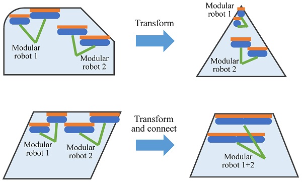
This paper discusses a method for window shape estimation based on a concept of nested reconfigurable robots for façade cleaning. The concept of nested reconfigurable robots for façade cleaning aims to develop robots that can be applied to autonomous façade cleaning on buildings with various types of architecture, such as a rounded glass surface and a spherical surface, shown in [4,27], improving the adaptability of façade-cleaning robots. In such various types of building architecture, while façade-cleaning robots work on flat glass panels connected by frames—called windows in this paper—especially in the case that window frames rise from window surfaces, they need to clean windows according to the frame shapes. The concept achieves autonomous façade cleaning according to window shapes, employing multiple modular multilegged robots capable of reconfiguring their morphology based on window shapes, which is executed by transforming their own modules and/or connecting with each other, and letting the robots cooperate (Figure 1). In the concept, the modular multilegged reconfigurable robots carry out tasks for façade cleaning, such as cleaning glass surfaces, the exploration of windows, and moving between windows through overcoming frames on each window.
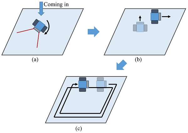
To achieve autonomous façade cleaning with the modular multilegged reconfigurable robot team, the window shape estimation is performed on each window by scanning window frames with one cleaning robot having an external sensor or a dedicated window scanning robot in the team. In the window shape estimation, a robot scanning a frame first searches for a part of the frame of the window the robot works on with an external sensor, turning at any initial point on the window the robot came in (Figure 2a). Once the robot detects a part of the window frame, the robot gets close to the window frame and starts moving along the frame, measuring the relative distance between the robot and the frame and the robot’s pose (Figure 2b). After going around the same trajectory along the frame, the robot estimates the window shape based on the measured data (Figure 2c). Performing the above way on each window produces all the shapes of the windows in a façade.
4. Window Scanning Robot
We consider that a façade-cleaning robot estimates a shape of a window it is on with data acquired by its own external sensor. In this paper, we focus on demonstrating the effectiveness of a method of the window shape estimation. Hence, we develop a robot to obtain window data with an external sensor, considering no façade-climbing mechanism, and validate a method of the window shape estimation with the developed robot through an experiment on a window placed on the ground.
The window scanning robot developed is shown in Figure 3, whose size is 189.7×138.7×191.9 mm and weight is 1.26 kg. The robot is equipped with a 2D laser range scanner installed perpendicularly to the ground to observe a window frame with little or no rising from the window surface because it is difficult to observe such a window frame with a 2D scanner installed horizontally. The robot can thus measure the relative distance between the robot and a window frame, moving on a window surface.
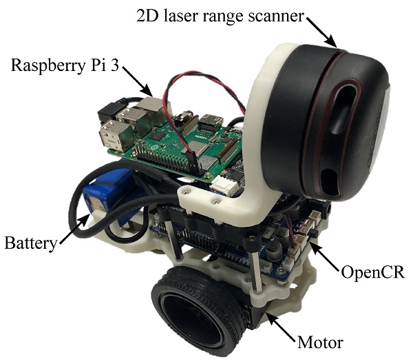
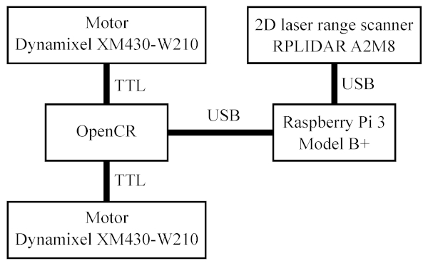
The system architecture of the window scanning robot is shown in Figure 4, which is developed on the basis of the architecture of TurtleBot3, the standard robot platform for the robot operating system (ROS). This system employs Raspberry Pi 3 Model B+ to activate the ROS, to which OpenCR, the open-source control module for ROS, and the 2D laser range scanner RPLIDAR A2M8 are connected via USB. OpenCR controls the motors Dynamixel XM430-W210 connected via the TTL communication interface, receiving a velocity command, and acquires data, such as the inertial measurement unit (IMU) and odometry, from sensors installed on the board. RPLIDAR A2M8 is controlled by Raspberry Pi 3 to obtain distance data from the robot to a window frame.
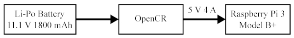
As shown in Figure 5, the 11.1 V 1800 mAh Li-Po battery is used for the power supply to OpenCR. From OpenCR, 5 V 4 A power is supplied to Raspberry Pi 3.
5. Window Shape Estimation
In this paper, the window scanning robot cannot capture the overall shape of a window at one time because the robot scans the frame of a window on its surface. Thus, the window shape estimation is accomplished by measuring the relative distance between the robot and the window frame with the 2D laser range scanner along the frame and arranging the points obtained by the scanner according to the robot’s pose.
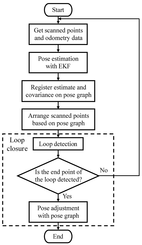
The flowchart of the window shape estimation is shown in Figure 6. In the estimation, the robot’s pose is estimated by the EKF [40,41] with the odometry data of the robot and is used to construct the pose graph of the robot. Based on the pose graph, the positions of the points obtained by the 2D scanner are recorded. In the loop closure [42], once it is detected that the robot reaches the end point of the loop of the robot’s trajectory, the pose adjustment is carried out to increase the accuracy of the window shape estimation.
The variables and parameters are summarized in Table 1 and Table 2.
Table 1. Variable descriptions.

5.1. Pose Estimation
The pose estimation of the window scanning robot is carried out, based on a model of the window scanning robot. Due to the simplicity of the robot model, the EKF [40,41] is employed to obtain the estimate and covariance of the robot’s pose and construct the pose graph of the robot.
5.1.1. Model of the Window Scanning Robot
The model of the window scanning robot used by the EKF is shown in Figure 7. In this model, 𝑂−𝑋𝑌 is the world coordinate, and 𝑂𝑐−𝑋𝑐𝑌𝑐 is the fixed coordinate to the robot, where 𝑂𝑐 is located on the center of the wheel shaft and 𝑌𝑐 is along the shaft.
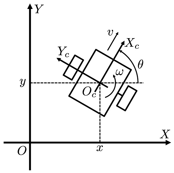
In the model, the motion of the window scanning robot is represented as

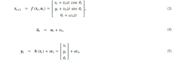
where (𝑥,𝑦) and 𝜃 are the position and the heading angle of the robot, and v and 𝜔 are the translational and rotational velocities, which are the input of the robot. Thus, let 𝒙𝑡=[𝑥𝑡,𝑦𝑡,𝜃𝑡]𝖳 as the robot’s pose at timestep t and 𝒖𝑡=[𝑣𝑡,𝜔𝑡]𝖳 as the input, the robot’s pose after travel time Δ𝑡 is given as follows:

Based on (2), the following state and observation equations are established for the EKF:
where 𝒗𝑡∈ℝ2 and 𝒘𝑡∈ℝ3 are the noise vectors for input and observation, respectively, and 𝒗𝑡∼𝑁(0,𝑸𝑡) and 𝒘𝑡∼𝑁(0,𝑹𝑡) with the covariance of noise 𝑸𝑡∈ℝ2×2 and 𝑹𝑡∈ℝ3×3. In the equations, 𝒖¯t denotes the input with the noise, and 𝒚𝑡 is the observation values, which is the odometry data in the window scanning robot.
5.1.2. Extended Kalman Filter
With the state and observation equations, we can obtain the estimate 𝒙̂ and covariance 𝑷 of the robot’s pose, according to the following algorithm of the EKF [40,41]:
Prediction step: The prior estimate 𝒙̂𝑡− and covariance 𝑷𝑡− are calculated by applying the estimate 𝒙̂𝑡−1, input 𝒖𝑡−1, and covariance 𝑷𝑡−1 in previous timestep as follows:

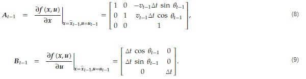
where the matrices 𝑨𝑡−1 and 𝑩𝑡−1 are given by linearizing 𝒇(𝒙,𝒖):
Update step: The posterior estimate 𝒙̂𝑡 and covariance 𝑷𝑡 are obtained by updating 𝒙̂𝑡− and 𝑷𝑡− calculated in the prediction step with the observation values 𝒚𝑡 as follows:

where 𝑮𝑡 is the Kalman gain calculated as
![]()
In (12), the matrix 𝑪𝑡 is given by linearizing 𝒉(𝒙):

By repeating the prediction and update steps in every timestep, the estimate and covariance of the robot’s pose are obtained to construct the pose graph of the robot.
5.2. Loop Closure
The loop closure [42] is carried out to reduce accumulated error on the EKF and obtain an accurate shape of window frames. Upon the setup of the window scanning robot, it is difficult to perform the loop closure based on scan matching because its 2D laser range scanner is installed perpendicularly to the ground. In this paper, the loop closure hence exploits the result of the pose estimation.
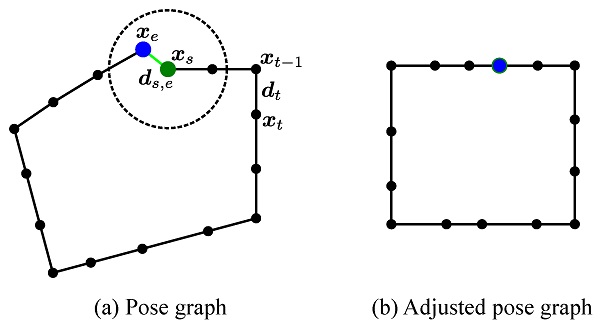
To carry out the loop closure, the pose graph 𝒢𝑇=(𝒳𝑇,𝒟𝑇) of the window scanning robot moving by the time T, as shown in Figure 8, is applied. In this pose graph, the vertices 𝒳𝑇 and the edges 𝒟𝑇 represent the robot’s poses 𝒙𝑡 in the world coordinate and the relative poses 𝒅𝑡=[𝑥′𝑡,𝑦′𝑡,𝜃′𝑡] between 𝒙𝑡−1 and 𝒙𝑡 in the fixed coordinate, respectively, that is, 𝒳𝑇={𝒙𝑡|𝑡=0,1,…,𝑇} and 𝒟𝑇={𝒅𝑡|𝑡=0,1,…,𝑇}. The pose graph allows us to execute the loop closure through loop detection and pose adjustment.
5.2.1. Loop Detection
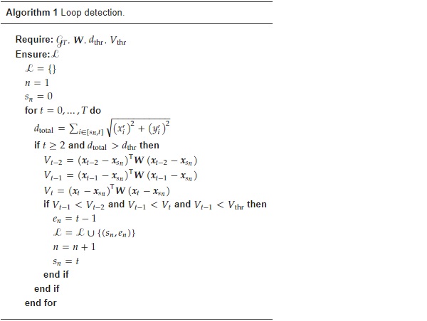
The loop detection, whose process is summarized in Algorithm 1, is carried out to obtain the set ℒ of a pair of the time stamps (𝑠,𝑒) of the start and end points 𝒙𝑠 and 𝒙𝑒 of a loop, based on the pose estimation with the EKF in this paper. On the assumption that the window scanning robot moves around the same trajectory along the window frame on its surface, i.e., at the end of a loop the robot comes back to its start, the loop detection is executed with the following algorithm:
Step 1: Let 𝑛=1, the time stamp 𝑠𝑛 of the start point 𝒙𝑠𝑛 of a loop is set.
Step 2: If the traveling distance
![]()
is larger than a distance threshold 𝑑thr, the evaluation value 𝑉𝑡 of 𝒙𝑡 is calculated as follows:
![]()
where 𝑾 is a weight matrix.
Step 3: If 𝑉𝑡−1<𝑉𝑡−2, 𝑉𝑡−1<𝑉𝑡, and 𝑉𝑡−1<𝑉thr, then the timestep 𝑡−1 of 𝒙𝑡−1 is set as the time stamp 𝑒𝑛 of the end point 𝒙𝑒𝑛 of the loop, where 𝑉thr is a value threshold.
Step 4: Once a pair of the time stamps 𝑠𝑛 and 𝑒𝑛 is given in the one loop, n is updated as 𝑛=𝑛+1 and the timestep t of 𝒙𝑡 is set as the time stamp 𝑠𝑛 of the start point of a new loop.
Steps 2, 3, and 4 are repeated until all the loops are detected.
5.2.2. Pose Adjustment
In the pose adjustment, the accurate pose graph is generated by reducing the accumulated error, as shown in Figure 8. The pose adjustment is executed by minimizing the following function with 𝒙:

where 𝒓𝑠,𝑒 is the relative pose between the start and end points, 𝒈(𝒙𝑡−1,𝒙𝑡) and 𝒈′(𝒙𝑠,𝒙𝑒) are the functions to calculate a relative pose from 𝒙 given as

𝑲 is covariance to settle the initial pose 𝒙0 to the initial estimate 𝒙̂0, and Σ𝑡 and 𝑺𝑠,𝑒 are covariance of the relative poses 𝒅𝑡 and 𝒓𝑠,𝑒, respectively. In this paper, 𝒅𝑡 and Σ𝑡 are obtained from the pose estimate 𝒙̂ and the covariance 𝑷 through the EKF as follows:

and 𝒓𝑠,𝑒, 𝑺𝑠,𝑒, and 𝑲 are adjustable parameters.
6. Experiment
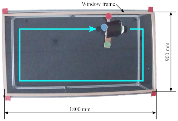
We demonstrate the effectiveness of the proposed approach through the experiment. In the experiment, the window scanning robot moves around the same trajectory along the frame of the rectangle window, whose size is 900×1800 mm, on its surface placed on the floor (Figure 9), thereby measuring the distance between the robot and its frame with the 2D laser range scanner installed perpendicularly to its surface. Using this experiment data, we carry out the pose estimation of the robot with the EKF offline and generate the robot’s pose graph which stores the pose estimate and covariance with thinning out to reduce the computational load. On the pose graph, all the pairs of the start and end points in a loop are acquired by the loop detection and then the pose adjustment is executed for the loop closure.
6.1. ROS-Based Experimental System
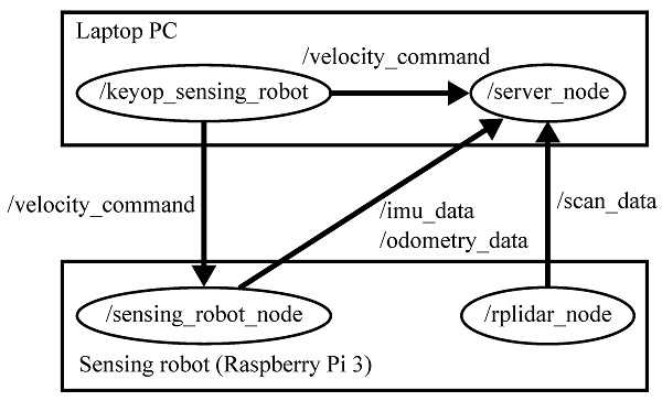
To carry out the experiment, the ROS-based system shown in Figure 10 was implemented. In this implementation, the keyop_sensing_robot node for the manual control of the window scanning robot is activated in a laptop PC to send /velocity_command. This command is processed by sensing_robot_node in Raspberry Pi 3 installed on the robot to generate motor input. sensing_robot_node concurrently provides imu_data and odometry_data. In the Raspberry Pi 3, rplidar_node is also activated to control the 2D laser range scanner and provides scan_data. These data are stored by server_node in the laptop PC to be applied for the evaluation of the proposed approach.
6.2. Variable and Parameter Settings
For the pose estimation with the EKF, we set the initial estimate and covariance of the robot’s pose
![]()
and the covariance of noise
![]()
For the loop detection and the pose adjustment, we set the following parameters:

6.3. Experimental Results
The results of the pose estimation and the loop closure are shown in Figure 11, Figure 12, Figure 13 and Figure 14. Figure 11 shows the robot’s trajectory and the scanned shape of the window frame obtained by the (a) measurement, (b) pose estimation, and (c) loop closure, respectively. This figure indicates the robot’s trajectories with lines and the positions of objects scanned by the 2D laser range scanner with dots, where we removed the dots indicating the positions of objects that are not located at the level of the window frame, such as a floor, walls, and ceiling. Figure 12, Figure 13 and Figure 14 show the time-series data of the robot’s position and heading angle.
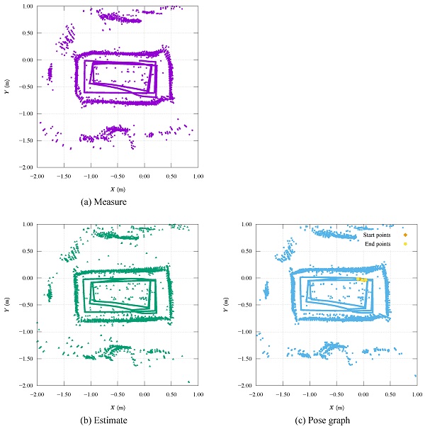
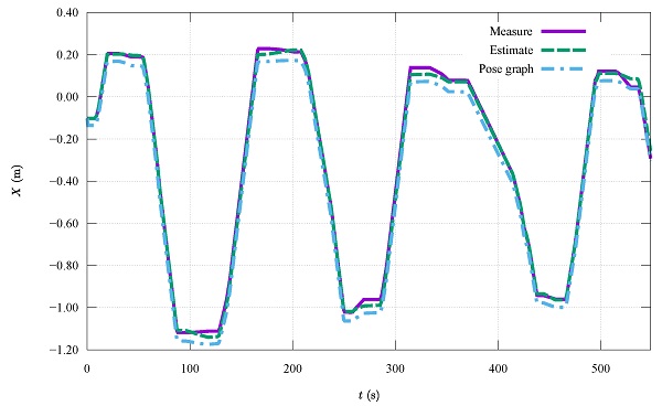
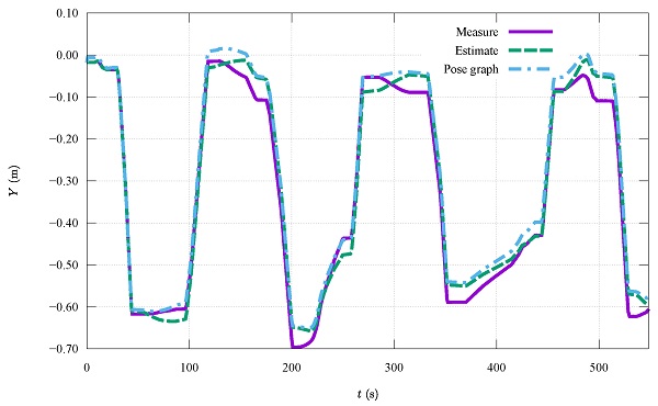
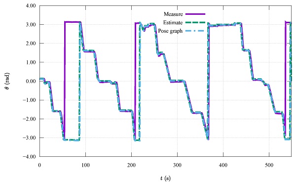
Figure 11a indicates that the window scanning robot was able to obtain the shape of the rectangular window frame, which is described outside the robot’s trajectory by the gathered scan dots along the trajectory, and the size of the scanned window is broadly correct. The dots forming the window shape can be distinguished from dots indicating other objects, although the window shape is slightly twisted. This result argues that the shape of a window frame can be measured by scanning a window frame perpendicularly to the window surface with a 2D laser range scanner and this task is viable by a robot on the scanned window.
Figure 11b declares that the pose estimation with the EKF reduces the error of the robot’s trajectory and thereby improves the accuracy of the window shape estimation. The window shape based on the estimates of the robot’s pose is less twisted than that based on the measurement data. This result presents that the pose estimation with the proposed model and the EKF contributes to increasing the feasibility of the proposed window shape estimation with a 2D laser range scanner.
Figure 11c shows that the loop closure based on the pose graph utilizing the estimates influences the estimated shape of the window frame. This estimated window shape is rarely different from that in Figure 11b. However, the isolated dots decrease in Figure 11c. This result indicates that the loop closure is effective for the window shape estimation but also implies the need to improve the proposed method.
In the time scale, Figure 12 and Figure 13 show that the loop closure adjusts the robot’s positions in the horizontal direction during translational movement. By contrast, it hardly affected the heading angle of the robot, as shown in Figure 14.
7. Conclusions
In this paper, we have presented an approach to estimating the shape of a window so that a façade-cleaning robot can acquire information about the window it works on. To this end, we developed a robot equipped with a 2D laser range scanner installed perpendicularly to the ground to observe a window frame and proposed a method of window shape estimation with the developed robot, consisting of pose estimation and a loop closure. For this method, the pose estimation with the EKF was employed and the loop closure algorithm based on the estimate of the robot’s pose was devised. This loop closure was accomplished by defining the start and the end point of a loop in the loop detection and modifying a pose graph of the robot in the pose adjustment. To demonstrate the effectiveness of the proposed approach, the experiment with the window scanning robot developed was carried out on a window placed on the floor. The experimental results have shown that the robot can acquire the window shape by scanning the window frame with the 2D laser range scanner installed perpendicularly to the window, and the proposed approach is effective for estimating a window shape it works on. In future work, we would improve the proposed approach to increase the accuracy of the window shape estimation. To this end, we will apply a different filter to the pose estimation, such as a fuzzy-based Kalman filter [49], and refine the method of the loop closure to increase the applicability to different shapes of windows. Moreover, we will carry out experiments using windows with rough glass surfaces to verify the influence of the geometry of window surfaces on the proposed approach.
Author Contributions
Conceptualization, T.N. and S.N.; methodology, T.N., S.N. and S.I.; software, T.N.; validation, T.N. and S.N.; formal analysis, T.N.; investigation, T.N. and S.N.; resources, S.N., M.I. and H.I.; data curation, T.N. and S.N.; writing—original draft preparation, T.N.; writing—review and editing, T.N., S.N., S.I., M.I. and H.I.; visualization, T.N.; supervision, S.N., M.I. and H.I.; project administration, S.N., M.I. and H.I.; funding acquisition, S.N. and H.I. All authors have read and agreed to the published version of the manuscript.
Funding
This research was funded by the Research Institute for Science and Technology of Tokyo Denki University, grant number Q18T-06 and 19T-08/Japan. The APC was funded by Q18T-06 and 19T-08/Japan.
Data Availability Statement
The data presented in this study are available on request from the corresponding author.
Acknowledgments
The authors would like to thank S. Sasaki and M. Sasahira for assistance with the experiments.
Conflicts of Interest
The authors declare no conflict of interest.
Abbreviations
The following abbreviations are used in this manuscript:
| EKF - | Extended Kalman filter |
| ROS - | Robot operating system |
| IMU - | Inertial measurement unit |