Article Information
- Digital Object Identifier (DOI): 10.47982/cgc.9. 534
- Published by Challenging Glass, on behalf of the author(s), at Stichting OpenAccess.
- Published as part of the peer-reviewed Challenging Glass Conference Proceedings, Volume 9, June 2024, 10.47982/cgc.9
- Editors: Christian Louter, Freek Bos & Jan Belis
- This work is licensed under a Creative Commons Attribution 4.0 International (CC BY 4.0) license.
- Copyright © 2024 with the author(s)
Authors:
- Dinith Ranaweera a,
- Behrouz Zafari a,
- Mauro Overend b
a Kingston University London, England
b TU Delft, Netherlands

Abstract
This study is part of a comprehensive research to develop a better understanding of the structural performance of Glass-GFRP composite façade panels. Composite sandwich façade panels exhibit significant potential for replacing non-composite counterparts, attributed to their superior structural strength and higher stiffness. These sandwich panels not only offer higher structural efficiency but also present the opportunity for a more visually appealing façade panels, allowing for slimmer profiles and greater spans. Nevertheless, the use of composite façade panels is to be investigated more prior to being utilized in the industry. Consequently, this study focuses on the structural performance of slender composite beams comprising of two glass face sheets with a GFRP core adhesively bonded to the face sheets representing a section of a larger panel. In the first phase of this study two different beam configurations are tested comprising of two sizes of GFRP cores, with two distinct wall thicknesses which are then compared against non-composite beams. Whereas the second stage of the study comprises of the long-term behaviour of these beams when subjected to staged long-term loading. The surface strain data and midspan deflection of the beams will be obtained from the specimens.
1.Introduction
1.1. Motivation
The motivation behind this research is to deepen the understanding of Composite Sandwich Façade Panels, a revolutionary concept with a potential to replace traditional non-composite façade panels and to redefine the future of minimalistic facades. Historically sandwich panels are often used in the façade industry as cladding panels, where two thin metal face sheets are bonded together with a lightweight and a less rigid core, resulting in a highly efficient structure with a high flexural rigidity and a lower density.
With the ever-growing architectural concepts such as minimalistic designs which uses slimmer structural elements with bigger spans, the implementation of sandwich façade panels would be highly beneficial to complement such design requirements. While the potential benefits of sandwich façade panels are evident, the practical implementation of such concepts in the construction industry demands a thorough investigation to ensure their performance and reliability. Therefore, our study focuses on an experimental testing to determine the structural performance of adhesively bonded glass-GFRP sandwich beams which would represent a segment of a larger sandwich façade panel.
In the initial phase the research examines two distinct beam configurations each featuring pultruded GFRP cores of different cross-sectional dimensions.
1.2. Research in composite glass beams
Composite glass structures have been researched by a few researchers in the past, where glass face sheets bonded to different types of framing material have been experimentally studied in order to assess the composite action. One such study conducted by Nhamoinesu and Overend (2014) compares the composite action between an adhesively bonded steel-glass composite panels with an unbonded counterpart, where the study reveals that the bonded panels have more than twice the ultimate strength when compared to the unbonded panel.
Within the context of composite beams several studies have explored the application of bonding fibre reinforced polymers to glass sheets to create composite structures. Notably Palumbo et al. (2005) and Louter et al. (2010) have performed research on composite glass beams with adhesively bonded fibre polymers however, one of the most recent and the most relevant study on this aspect is the study conducted by Pascual et al. (2016). This extensive research study has focused on experimental investigation of Glass-GFRP composite beams constructed using a pultruded GFRP core adhesively bonded to two fully tempered glass sheets. This study has mainly focused on developing and validating a new analytical model to predict the deflection and strain of the above-mentioned beam configuration.
At present bonded connections are widely used in the façade industry with structural silicone being the most used adhesive. These structural silicone glazing units are rising in popularity in the modern architectural designs due to the ability to produce seamless façade panels Alcaine et al. (2020). However, in order to achieve an effective level of composite action between the bonded material, the elastic modulus of the adhesive used is extremely important as per the numerical modelling conducted by Tomasi et al. (2013). As per the research published by Tomasi et al. (2013), an elastic modulus of at least 0.2 GPa is required to create a good level of composite action between glass and GFRP components. Therefore, the use of structural silicone for composite purposes is not recommended as the elastic modulus is between 1.39 to 2.03 MPa Lee et al. (2018).
Henceforth, investigations into the utilization of stiffer adhesives have been undertaken by researchers such as Pascual et al. (2016), wherein the efficacy of employing a two-part self-curing epoxy, specifically the DP490 formulation by 3M, has been empirically validated for facilitating bonded connections between glass and GFRP. Furthermore, comprehensive research efforts led by Belis et al. (2011) have examined the impact of aging on the strength characteristics of adhesively bonded connections. It was observed that the DP490 adhesive experienced a 29% reduction in bond strength after a 12-week aging period, yet retained a superior bond strength compared to alternative adhesives examined within the scope of this study.
1.3. Objectives
The primary objective of this experimental study is to determine the structural efficacy of Glass-GFRP composite facades that are more structurally efficient and durable. Beams prepared using two glass face sheets and an adhesively bonded GFRP core were tested to evaluate the structural performance of the above concept. These beams were tested under monotonic loading condition to measure the ultimate load bearing capacity and mid span deflection. Whereas some of the beams were tested under staged long-term loading to measure the creep behavior of these GFRP-Glass composite beams which will be very beneficial prior to commercial use of such concepts.
2. Experimental process
2.1. Test specimens
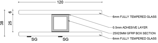
In this phase of the experiment, ten specimens of 950 mm long composite beams were tested. These beams compiled of two 6mm fully toughened glass face sheets meeting BS EN 12150 standards, which were adhesively bonded to a pultruded Glass Fiber Reinforced Polymer (GFRP) core. The bonding process involved the use of 3M ScotchWeld DP490 2-part self-curing epoxy adhesive with a controlled bond line thickness of 0.5 mm. To ensure uniformity, two aluminum tabs of 0.5 mm thickness were positioned at both ends of the GFRP core to regulate the bond thickness.
Following the bonding process, all beams underwent a minimum curing period of 7 days as recommended by the manufacturer. The bond surface of the GFRP core was prepared by lightly sanding it with 240 grit sandpaper to enhance bonding strength. Additionally, all bonding surfaces were meticulously cleaned using Isopropyl Alcohol (IPA) to remove any contaminants and optimize adhesive performance.
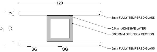
The composite beams featured two distinct cross-sectional configurations, as outlined in Table 1. Among these, seven beams were characterized by a smaller 25 mm x 25 mm pultruded Glass Fiber Reinforced Polymer (GFRP) core, while three beams showcased a larger 38 mm x 38 mm pultruded GFRP core. Detailed illustrations of these cross-sectional configurations are provided in Figure 1 and Figure 2, respectively, for reference and clarity.
All beams underwent testing using a four-point bending configuration, with seven of them subjected to monotonic loading until their ultimate failure. Conversely, the remaining three beams were subjected to staged long-term loading to evaluate the creep behavior of sandwich beams. Table 1 below presents the various specimen configurations tested in this series, along with the designated ID’s assigned to each beam.
Table 1: Details of Specimens.
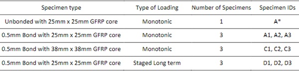
The pultruded GFRP profiles used in the specimens were manufactured by Engineered Composites UK, where the 25 mm x 25 mm RHS had a wall thickness of 3 mm whereas the 38 mm x 38 mm RHS had a wall thickness of 5 mm. Hence both the profiles are classified under the E17 classification as per BS EN 13706 specification.
All the glass face sheets were covered with a thin plastic protective film to prevent the spread of glass particles and to reduce the risk of injury, which also helped analyze the crack patterns of the glass.
3. Test procedure
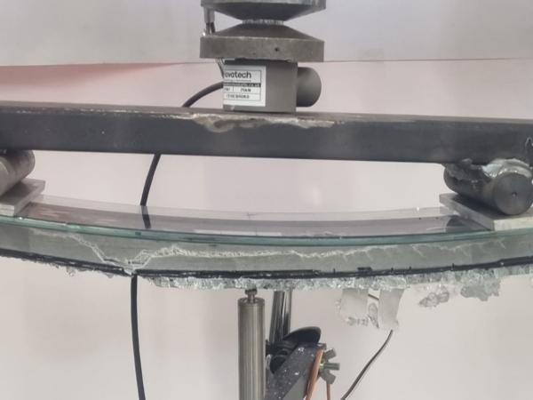
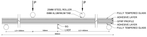
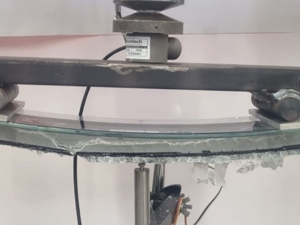
For the monotonic loading test configuration, the beams were supported on a metal frame as shown in Figure 3, and the load was applied using a manually controlled hydraulic jack at a stroke rate of 1mm/min. The applied load was measured using a duly calibrated 50 kN load cell manufactured by NovaTech, while a 50 mm LVDT transducer placed at the bottom glass face sheet of the beam measured the midspan deflection. The hydraulic jack was connected to a metal distribution frame with two steel rollers at a span of 300 mm, whereas the specimen was rested on two steel rollers at a clear span of 900 mm. To prevent localized stresses and to prevent premature failure on the glass face sheets, all four contact points between the glass and the steel support rollers were fitted with 6mm aluminum tabs spanning the full width of the specimen.
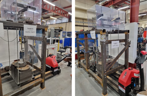
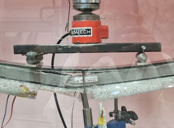
In the long-term staged loading configuration, the beams were supported on a specially fabricated steel frame designed to meet the experimental requirements. The beam support and loading locations were maintained as depicted in Figure 3. However, instead of a hydraulic jack, static weights were utilized to load the specimens. This approach was chosen because a hydraulic jack would not provide a constant load while compensating for the beam's constant creep.
The loading frame, as illustrated in Figure 4, featured a metal base used to stack steel weight plates. These plates were then placed on a load distribution plate resting on the specimen. To ensure uniform loading and measure any asymmetric loads, two 25 kN load cells were positioned at either end of the load distribution bar. Additionally, a mid-span LVDT transducer was employed to measure the mid-span deflection of the beams.
Furthermore, a type K thermocouple was placed near the specimen (only in D2 and D3) to monitor ambient temperature changes. This monitoring aimed to identify any direct correlation between ambient temperature variations and the rate of creep exhibited by the beams during the long-term staged loading tests.
The long-term staged loading protocol consisted of four distinct stages, each lasting 7 days (168 hours), during which a predetermined static load was applied to the specimen. In stage one, the beam was loaded to 40% of the mean failure load observed in the monotonic loading experiment. Subsequent stages involved incrementally increasing the load by 10% until stage four, where the load reached 70% of the ultimate mean failure load. Following each stage, the beam underwent an unloading period and was left unloaded for 20 minutes to assess its ability to recover to its original position.Table 2 outlines the specific loads applied during each stage of the long-term loading process.
Table 2: Loads used for long term loading experiment.

4. Results and discussion
4.1. Monotonic loading condition
This section discusses the composite behavior of the beams in comparison to their non-composite counterparts. Table 3 presents the maximum load, mid-span deflection, and failure pattern observed in all the beams tested under monotonic loading conditions.
Table 3: Monotonic loading experimental results.
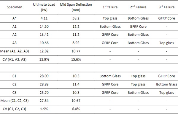
The series of beams with a 25 mm core (A series) exhibited a mean failure load of 12.82 kN and a mid-span deflection of 10.77 mm, as detailed in Table 3. A comparative analysis with the unbonded counterpart revealed a substantial enhancement in performance for the composite beams, with an increase of 312% in ultimate load capacity. Notably, the mid-span deflection showed a significant improvement, with the composite beams demonstrating a 5.4 times reduction in deflection at first failure compared to the control sample.
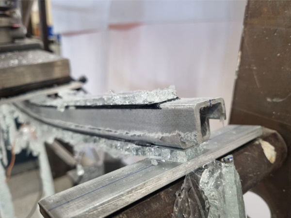
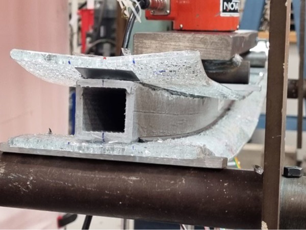
Failure mechanisms in the composite beams were observed to slightly vary across specimens. While specimen A1 experienced failure at the GFRP core, specimens A2 and A3 exhibited failure due to horizontal shear within the GFRP core (Figure 8 and Figure 8). Cracks initiated from the beam's edge and propagated towards the center as deflection increased, leading to ultimate failure. It is noteworthy that specimens A1 and A2 reached the maximum stroke length of the jack before the third failure occurred, whereas specimen A3 experienced its third failure just before reaching the maximum stroke limit of the hydraulic jack. These findings underscore the complex failure modes and performance enhancements associated with composite beam structures.
It is important to acknowledge that during the initial failure of specimen A1, the load cell wire sustained damage, resulting in the suspension of data collection subsequent to the first failure. However, the test continued until reaching ultimate failure to observe of the failure pattern. Additionally, in specimen A*, small dots of cyanoacrylate (CA) glue were applied between the GFRP core and the face sheets to secure the beam in position during placement on the test rig. It is noteworthy that these glue points, situated at both ends of the beam, experienced debonding, causing dips in the load vs. deflection curve approximately at 3 to 5 mm of mid-span deflection.
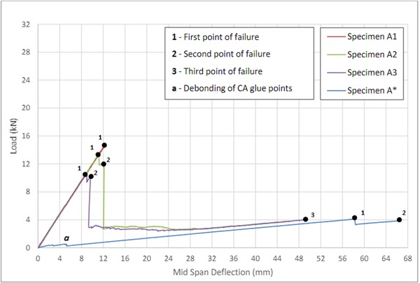
The plot in Figure 5 shows the load vs. deflection graph for the A series of specimens including the unbonded variant A*. As the graph shows the 3 bonded specimens have a similar gradient until the first failure point, whereas the unbonded specimen shows as much lower gradient indicating a lower stiffness. However the post failure gradient of the bonded specimens show a similar gradient to the unbonded specimen. Therefore it can be concluded that after the failure of both the GFRP core and the bottom glass the bonded beams acts similarly to the unbonded beam.
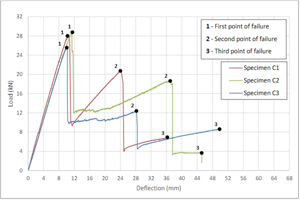
On the other hand, the specimens with the 38 mm core (C series) had a significantly higher average ultimate failure load recording an average load of 27.54 kN which was more than 250% higher than the “A” series of beams. The deflection at first failure was on par with the mean deflection of the “A series” of specimens, where series “C” showing a slight reduction of 0.1 mm. it should also be noted that the C series of beams had a lower coefficient of variation compared to the A series of beams as depicted in Table 3.
Unlike the A series of beams, the C series had a varied failure mode where C2 and C3 (Figure 10) beams failed first in the GFRP core whereas the specimen C1 failed first in the bottom face sheet where by the GFRP core failed at last (Figure 9). However, considering the coefficient of variation of the results, it can be concluded that the varied behavior is likely due to each component in the beam operating at its maximum capacity. Consequently, minor variations in the material structure could result in different members failing earlier than others.
4.2. Long term loading condition
In this section the results of the long-term loading condition are explained, and the results are compared against the monotonic loading condition to observe any differences in the beams performance. As mentioned in section 3, Mid span deflection and the ambient temperature fluctuations were measured along with the mid span strain data however it should be noted that the strain data is not published in this paper. Each loading stage was analyzed individually where the mid span deflection at the end of 168 hours is shown below in Table 4 along with the mean deflection for each round.
Table 4 - Results of Long-term loading.
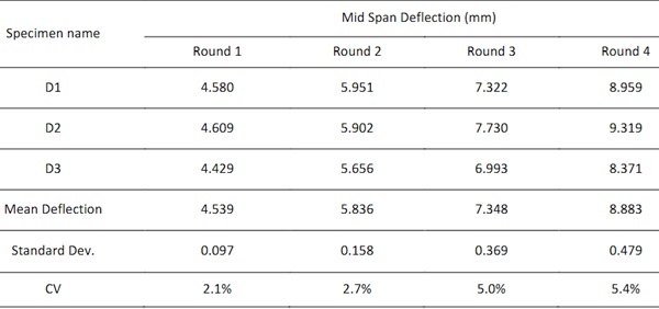
As shown in Table 4, the coefficient of variation of the results increase as the load is increased. Therefore it is evident that as the load is increased the creep performance of the beams tends to be less consistent, leading to a higher variability in the results.
The ambient temperature fluctuations in the test area were monitored for specimens D2 and D3, and the correlation between temperature fluctuation and mid-span deflection throughout all four stages of loading is illustrated in Figure 11 and Figure 12. Each loading stage is marked on the graphs, with the time vs. deflection curve starting from the permanent deflection sustained by the beam at the beginning of each stage.
The graphs clearly depict that the gradient of the time vs. deflection curve increases with rising ambient temperatures. Notably, a significant change in gradient is observed during stage 3 of specimen D2, coinciding with the highest recorded ambient temperatures during the experimental period, leading to the steepest curve on the graph. This observation suggests a direct link between ambient temperature variations and the long-term creep behavior of the beams.
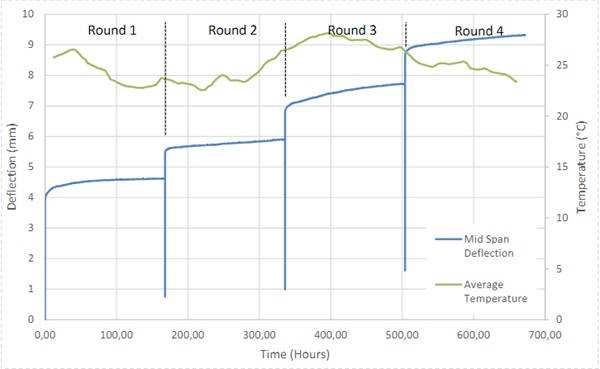
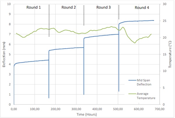
These findings emphasize the importance of considering ambient temperature fluctuations when assessing the structural performance and creep characteristics of composite beams, highlighting the influence of environmental factors on material behavior and structural integrity.
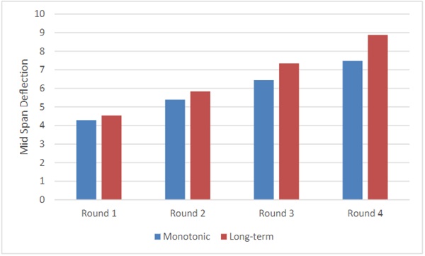
The graph presented above compares the mean mid-span deflection between the monotonic loading condition and the long-term loading condition. To ensure comparability, the mid-span deflection at the respective mean loads used in the long-term loading condition was employed for the monotonic loading condition.
The results clearly indicate that as the load increases, the difference in mid-span deflection between the two loading conditions also increases significantly. At the end of Round 1 of loading, the mid-span deflection in the long-term testing was 5.9% higher than in the monotonic test. However, by Round 4, this difference had escalated to 18.8%. This observation underscores the progressive divergence in deflection behavior between the two loading scenarios as the applied load intensifies, highlighting the dynamic nature of structural response under varying loading conditions.
5. Conclusion and Future research
In conclusion, this research has contributed to a deeper understanding of Composite Sandwich Façade Panels, particularly focusing on Adhesively bonded Glass-GFRP sandwich beams. The experimental testing conducted on various beam configurations under monotonic and long-term loading conditions provided valuable insights into their structural performance and long-term creep behavior.
The results of the monotonic loading tests revealed that the composite beams with adhesively bonded glass face sheets exhibited significantly higher ultimate failure loads and reduced mid-span deflections compared to the non-composite counterpart. The failure patterns observed in the GFRP core and glass face sheets under different loading conditions provided critical information for optimizing the design and construction of sandwich façade panels.
Furthermore, the long-term loading tests highlighted the creep behavior of the sandwich beams, showing an increase in mid-span deflections as the load and ambient temperature fluctuations increased over successive loading stages. The correlation between ambient temperature and beam deflection suggests the importance of considering environmental factors in the long-term performance assessment of composite sandwich panels.
Hence as future work it would be critical to conduct experiments focusing on the effect of ambient temperature on the creep behavior of the beams. Also it should be noted that creep of the beams did not pause by the end of each 168hr cycles as predicted by the researchers, therefore a much longer term experiment would provide a more detailed overview on the practicality of such composite beams in façade construction.
However, the extent of creep's influence is dependent upon the specific application context. For instance, in the context of façades, which primarily encounter short-term wind loads resembling cyclic loading conditions, the impact of creep is comparatively mitigated. Conversely, within flooring systems, where panels sustain long-term dead loads alongside medium-term superimposed loads, creep behavior assumes greater significance. Therefore, when employed in façade applications, the concern surrounding the panels' creep behavior can be rendered less critical.
Acknowledgements
The authors would like to extend their sincere appreciation to Engineered Composites UK for providing the pultruded GFRP sections utilized in this research. Their support was invaluable in advancing the understanding of composite materials and their applications. Additionally, heartfelt thanks to Dashan Peiris for his help given with the preparation and testing of the samples.
References
Alcaine J, Lenk P and Forwood E (2020) ‘Structural Silicone Glazing –Design & Modelling’, Challenging Glass 7 [Preprint]. doi:https://doi.org/10.7480/cgc.7.4548.
Belis JLIF, Hulle, van A, Out B, Bos FP, Callewaert D & Poulis H 2011, Broad screening of adhesives for glass-metal bonds. in Proceedings of Glass Performance Days 2011. Tampere, Finland, pp. 286-289, Glass Performance Days 2011, Tampere, Finland, 16/06/11.
BS EN 12150-2: 2004: Glass in building. Thermally toughened soda lime silicate safety glass. Evaluation of conformity/Product standard. British Standards Institution, London (2004)
BS EN 13706-2:2002: Reinforced plastics composites — Specifications for pultruded profiles. British standards Institute, London (2002)
Lee AD, Shepherd P, Evernden M C, Metcalfe D(2018) ‘Doubletstraat, 181, pp. 510–526. doi:10.1016/j.conbuildmat.2018.06.038.
Louter C, Leung C, Kolstein H, Vambersky J. (2018) Structural glass beams with embedded glass fibre reinforcement. In: Proceedings of challenging glass 2, Delft, 20–21 May 2010. p. 439–48.
Nhamoinesu S and Overend M (2014) ‘Challenging Glass 4 & COST Action TU0905 Final Conference’, in The mechanical performance of adhesively bonded steel-glass composite panels: medium-scale tests and numerical models. CRC Press.
Palumbo D, Palumbo M, Mazzucchelli M. A new roof for the XIIIth Century ‘‘Loggia de Vicari” (Arqua Petrarca – PD – Italy) based on structural glass trusses: a case study. In: Proceedings of glass processing days, Tampere, 17–20 June 2005. p. 434–35.
Pascual C., Montali J. and Overend M. (2016) ‘Adhesively-bonded GFRP-glass sandwich components for structurally efficient glazing applications’, Composite Structures, 160, pp. 560–573. doi:10.1016/j.compstruct.2016.10.059.
Tomasi A, Mocibob D, van de Linde B, Wellershoff F, Koldtoft K. Tec facade – glass as functional façade element. In: Proceedings of COST action TU0905 mid-term conference on structural glass, Porec, 18–19 April 2013. p. 349–57.


 demonstrator at Glass Technology Live during Glasstec 2024 (© Cas Maertens).")