This paper was first presented at GPD 2023.
Link to the full GPD 2023 conference book: https://www.gpd.fi/GPD2023_proceedings_book/

Authors:
- Ali Haydar(1-2)
- Alberto Consolaro(1)
- Massimo Maffeis(1)
- Gianni Royer-Carfagni(2)
(1) Maffeis Engineering SpA, Via Mignano 26, Solagna (Vi), Italy
(2) University of Parma, Parco Area delle Scienze 181/A, I43100 Parma, Italy
Abstract
We present exact expressions for the effective thickness of laminated glass beams, which can be readily implemented in an Excel spreadsheet for practical design purposes. These are derived from a recently proposed analytical model, which relies on a modified version of the refined zig-zag theory for layered composites, in which the glass plies are Euler–Bernoulli beams, whereas the polymeric interlayers provide for their shear-coupling. Under the quasi-elastic approximation, the polymer is considered linear elastic, with a shear modulus parametrically depending on time and environmental temperature. The analytical solution can be found, in closed form, for laminated packages of arbitrary composition, when the beam is statically determined.
Here, the exact expressions for the deflection- and stress-effective thicknesses are worked out for the important case of cantilevered laminated glass balustrades under distributed and/ or concentrated loads, schematized as a short simply supported beam with a long cantilevered overhang. We show that the cross-sectional warping allowed by the end constraint of a U-shaped base shoe, as well as the highly asymmetrical deformation, render inaccurate the traditional effective-thickness formulations mentioned in Standards, such as the Wölfel-Bennison or the EET methods. The results are in agreement with the more recent Conjugate Beam Effective-Thickness (CBET) method, only available for three-layered packages. The formulation here proposed is much more general since it can be applied to multi-laminates of arbitrary composition.
1. Introduction
Laminated glass (LG) is composed of layers of glass, with very high stiffness, sandwiching soft polymeric interlayers. This alternation of layers with highly different stiffnesses places LG in a particular class of laminates, characterized by a peculiar zig-zag warping of the cross-section: the stiffer glass plies are subjected to bending, whereas the role of the soft polymeric interlayer is to provide their shear coupling. Therefore, the bending capacity of LG falls between the two well-known borderline cases of monolithic and layered limits. For an LG glass beam, the flexural inertia at the monolithic limit corresponds to the moment of inertia of the glass cross-section; at the layered limit, to the sum of the moments of inertia of the glass plies.
The evaluation of the actual degree of coupling offered by the interlayers as a function of their stiffness is one of the most investigated problems in glass engineering. A very common practical approach consists in defining the Effective Thickness (ET) of LG, i.e., the thickness of a monolith with equal bending properties in terms of stress (stress-ET) and deflection (deflection-ET). In general, this definition is derived under the quasi-elastic approximation, according to which the interlayer is assumed linear elastic, with a secant shear modulus parametrically depending on the duration of the applied actions and environmental temperature. In general, the ET depends upon the stiffness and thickness of the interlayer, as well as on geometry, type of loading and boundary conditions. Several models have been proposed to calculate the ET. The most commonly used are the Wölfel-Bennison (W-B) approach [1], mentioned by ASTM standards, and the Enhanced Effective-Thickness (EET) [2], method, included in the new Eurocode [3]. However, both approaches may provide inaccurate results when the warping of the end cross sections plays a dominant role. This occurs, in particular, in the case of highly asymmetric geometry and/or loading.
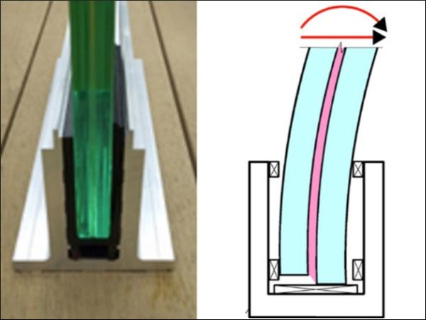
To this respect, a paradigmatic example is represented by cantilevered LG balustrades, whose base is typically inserted in a U-shaped shoe support, as indicated in Figure 1a. Figure 1b shows a scheme of the deformed configuration, for which it is clear that the warping of the end cross-section is not constrained.
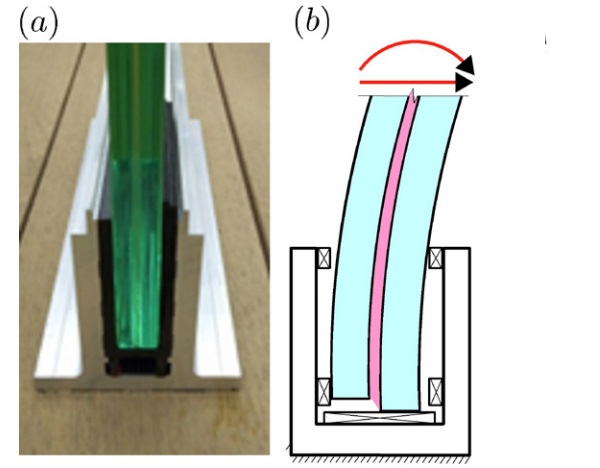
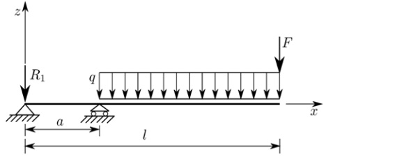
This end warping is enhanced by the resulting static scheme, represented in Figure 2, characterized by a short simply supported beam (of length a), where shear concentrates, and a long cantilevered overhang (of length, l - a), which can be subjected to a distributed load q (representative of wind) and/or a concentrated force F (the barrier load). To overcome this difficulty, the conjugate beam effective-thickness (CBET) method [4], [5], has been recently proposed. However, its limitation is that it can consider, at least in the version proposed so far, three-layered packages only.
Here, we propose a new approach to the problem, which is valid for multi-laminate beams with any number of glass plies and interlayers of arbitrary thickness. The theoretical foundations of the model and its numerical implementation in a simple FEM code, to solve the most general cases, are detailed in [6]. When the beam is statically determined, the differential governing equations can be analytically integrated, as shown in [7] for the representative example of LG balustrades. For this case, both the W-B and the EET methods are inaccurate, because of the high variability of shear coupling of the glass plies along the beam axis. The analytical method allows to calculate the displacement and the average shear angle in all points of the beam axis.
The theoretical foundation of the model is a modified version [6] of the refined zig-zag theory for laminates [8], in which the glass plies are Euler-Bernoulli beams, whereas the thin interlayers are only subjected to shear stress, supposed constant in their thickness. Because of this, we will refer to it as the “Special Zig-zag model”, in short SZ. Our purpose now is to summarize all the expressions that are sufficient to calculate the deflection- and stress-ET, in order to render this approach more useful for the engineer of the practice. All the required formulas can be readily implemented in an excel spreadsheet for the purposes of design and verification. In addition, we report a comparison with the results obtainable with the W-B, the EET and the CBET approaches.
2. Formulation
Figure 3 shows the composite package forming the cross-section of an LG beam of total height h, width b composed of N layers of which (N+1)/2 glass plies, with odd numeration, and (N-1)/2 polymeric interlayers, with even numeration. Specifically, a generic layer k є (1,N) has a thickness hk and is made of glass when k is odd, or of polymer when k is even. This notation simplifies the definition of the geometric properties of the cross-section, related to the solution.
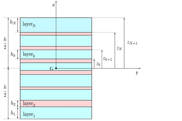
Introduce the reference system (y, z), with origin in the geometric centroid G of the cross-section, such that the kth layer is comprised between zk and zk+1, with zk+1-zk=hk . Let E denote Young's modulus of glass layers and Gp the shear modulus of the polymeric interlayers.
Based on the refined zig-zag theory proposed in [8], the warping of the cross-section is determined by a zig-zag shape function. This is defined by shear stress equilibrium at the layer interfaces, supposing that the slope of the zig-zag function is constant over each layer, as it is the case when the layers are thin. Consequently, the slope of the zig-zag function results to be [6]
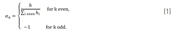
From (1) the value of the zig-zag function at the interfaces between the layers k and k+1 reads
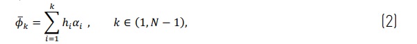
which satisfies the condition that the zig-zag function vanishes on the outer surfaces of the laminate [8], i.e.
![]()
The model requires the calculation of the geometrical properties of the cross-section. In the case of a symmetric composite package, these are represented by
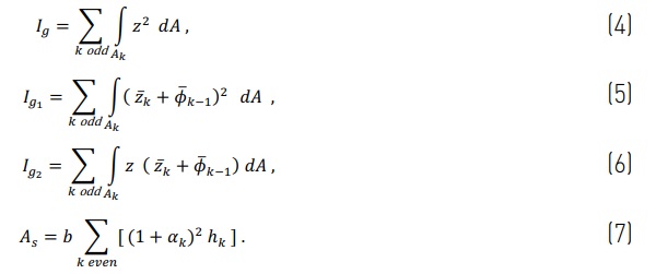
Here Z¯k is the coordinate where the kth layer starts, Ig is the cross-sectional moment of inertia at the monolithic limit, Ig1 and Ig2 are effective moments of inertia that result from the definition of the displacement field, and account for the effect of average shear angle of the laminated section, whereas As is the equivalent shear area of the interlayers.
3. Deflection- and stress-effective thickness
The two load conditions represented in Figure 2 by a uniformly distributed load q and a concentrated tip force F have been considered. Relying on the analytical solution of [7], we calculate the exact expressions for deflection under both actions. The maximum deflection is set equal to that of a monolithic beam with the same static scheme, whose moment of inertia shall be Imq under the distributed load q, and ImF under the concentrated force F.
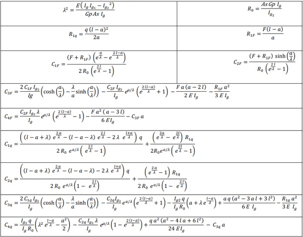
All the constants necessary to calculate the following effective thicknesses are reported in Table 1.
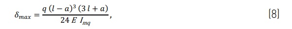
The maximum deflection of a monolithic beam under the distributed load q reads
whereas, in the case of the concentrated force F, it becomes

From the analytical solution one obtains
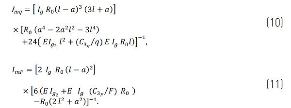
Obviously, the expression for deflection effective thickness is
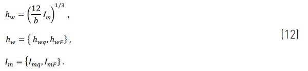
It will be shown later in Figure 12 that both expressions provide very close results. This means that the effective thickness has a mild dependence on the loading configuration. Similarly, one can match the maximum stress, obtained via the analytic solution, with the stress in an equivalent monolithic beam, i.e.
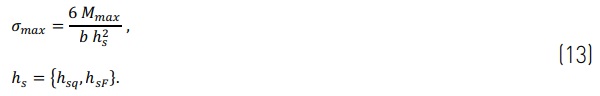
Where Mmax is the maximum bending moment for the considered loading configurations, while hs is the stress effective thickness. Therefore, one obtains, for the distributed load
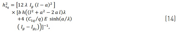
and
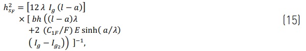
under the concentrated force.
Again, (compare Figure 12), the stress-effective thickness is only mildly affected by the load configuration.
4. Results and comparisons
For the beam in the static scheme of Figure 2, with α = 0.1 m, l =1.1 m" , consider a three-layered cross-section of width b =1 m, formed by two glass plies of thickness hg =12mm", sandwiching an interlayer of thickness hp = 1.52 mm", for which we shall consider multiple values of the shear modulus (Gp =0.1,1,10,100 MPa).
4.1. Uniformly distributed load
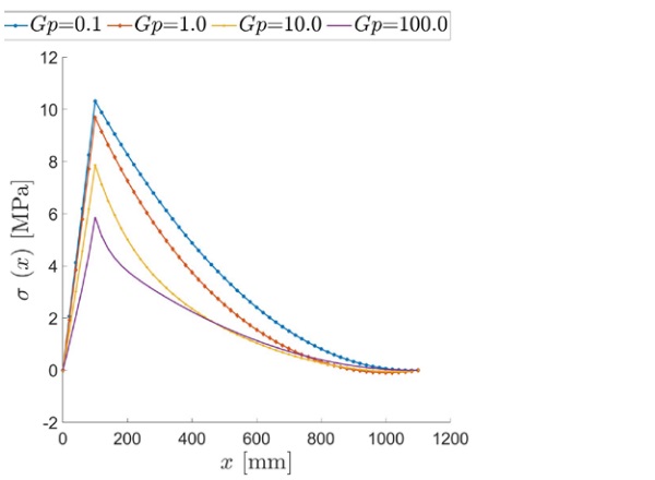
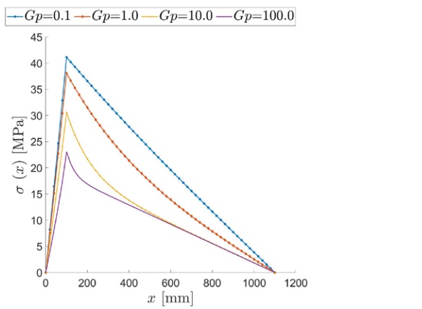
Firstly, we show the results for the beam under uniformly distributed load q =1 kN/m. The maximum tensile stress, occurring at the extrados of the upper glass ply, is shown in Figure 4 as a function of the axial coordinate x, for various values of the interlayer shear modulus.
Observe that the shape of the graphs slightly deviates from that of the bending moment, determined by equilibrium. This deviation is justified by the fact that the warping of the cross-section is variable along the beam axis; hence, also the degree of shear coupling between glass plies through the interlayer is variable. Therefore, the laminated beam behaves like a monolithic beam with a variable cross section. In the case of intermediate values of the shear modulus, namely Gp = 1-10 MPa, the stress at the extrados becomes slightly negative near the free end x=l, due to the straining of the interlayer, which compresses both glass plies where the curvature is vanishing, as in a neighborhood of the free ends. This effect is noticeable when the interlayer is neither too soft (layered limit) nor too stiff (monolithic limit).
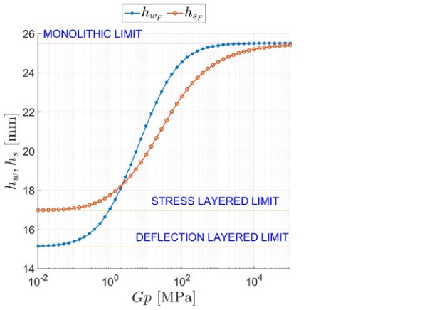
The deflection- and stress-ET under distributed load are reported in Figure 5 as a function of the interlayer’s shear modulus Gp є (102, 105) MPa. The static scheme of the balustrade implies high shear stress in the interlayer, especially for x є (0, α). This is why the monolithic limit is not reached even when the interlayer is very stiff (Gp ≅ 10² MPa). On the other hand, even a very soft interlayer (Gp = 10⁻¹ MPa) can still produce some shear coupling between the glass plies.
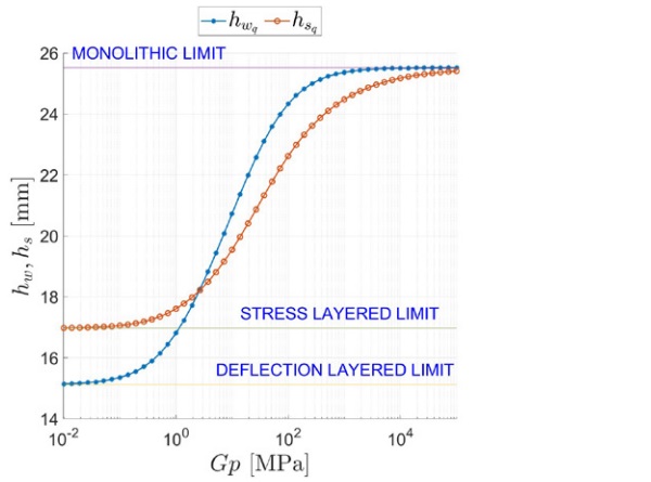
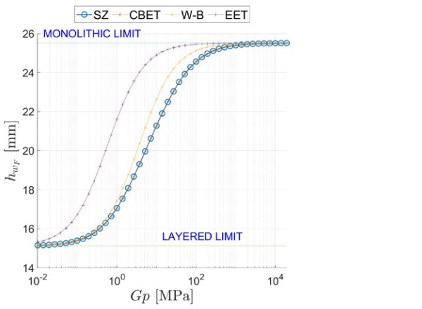
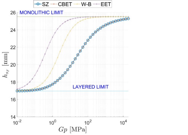
Figure 6, and Figure 7 report a comparison between the ETs calculated using the proposed model, labelled SZ (special zig-zag), and other approaches, namely the W-B [1], the EET [2], and the CBET [4], [5] approaches. There is an excellent agreement between the SZ and CBET approaches, which both correspond to an exact analytic solution. However, the SZ framework is much more general since it applies to multilaminate of arbitrary composition.
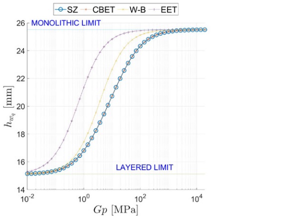
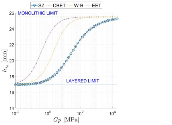
Since the CBET method has been corroborated by numerical simulations with Strand7(2015), the excellent fitting confirms the goodness of the SZ approach. On the other hand, both the EET and the W-B methods overestimate the effective-thicknesses, which results in the underestimation of the deflection and stress. This error stems from the fact that these approaches cannot properly consider the strong effect of the asymmetrical deformation of the beam and the consequent crosssectional warping at the supported end.
4.2. Concentrated tip force
Now the beam is loaded by a concentrated tip force F =2 kN at the free end x = l, as per Figure 2.
Figure 8 shows that the stress at the extrados evidently deviates from the linear trend of the overall bending moment, especially in a neighborhood of x = α, where the shear is dominant. This deviation is the more marked, the stiffer the interlayer is. Contrarily to the distributed load case of Figure 4, now the extrados is everywhere under tensile stress because the effect of the beam curvature is always greater than the axial forces induced by the straining of the interlayer.
The stress- and deflection-ET are plotted in Figure 9 as a function of the interlayer’s shear modulus Gp є (10⁻², 10⁵) MPa. Figure 10 and Figure 11, which are respectively the counterparts of Figure 6, and Figure 7, represent the comparison between the current model SZ and other effective thicknesses approaches. At the qualitative level, one finds the same characteristic features of the distributed load case.
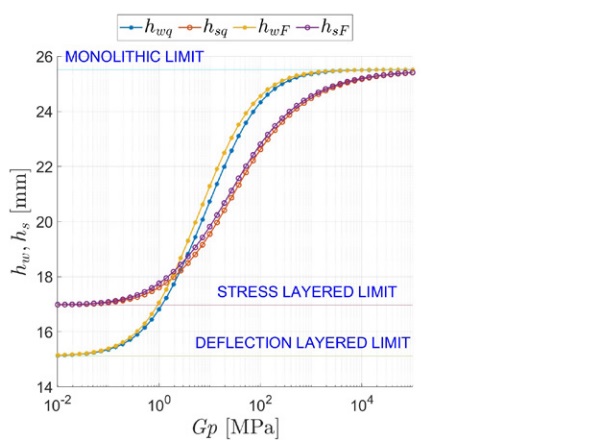
A synoptic comparison between the ETs hwq and hsq in case of distributed load, and the corresponding values hwF and hsF, for the concentrated force, is reported in Figure 12. It is evident that, at least for the worked example, the effect of the type of loading has only a mild effect, although the analytical expressions are formally quite different.
5. Conclusions
The recently-proposed refined zig-zag theory for layered composite beams has been applied to a case study of practical importance, represented by a cantilevered laminated glass balustrade under uniformly distributed and concentrated loads. The type of constraint is that of a U-shaped base shoe, which does not prevent the warping of the end cross section and provides the static scheme of a short simply supported beam with a long cantilevered overhang. This problem is characterized by a highly asymmetrical deformation and the concentration of shear stress, especially in the simply-supported portion, which enhance the warping of the end section, affecting the overall structural response.
We find that the trend of the maximum tensile stress, usually occurring at the beam extrados, deviates from the shape of the diagram of the bending moment, because the shear coupling of the glass plies through the interlayer is highly variable along the beam axis. Because of this, a monolithic beam with equivalent bending properties would present a variable cross section.
Exact analytical expressions for the effective thicknesses have been proposed for the maximum deflection and stress, according to the traditional definition. These can be easily implemented in an excel spreadsheet for practical design. Results are in perfect agreement with another recently proposed analytical method, which however can only handle three-layered composites. The proposed approach is much more general since it applies to laminated packages of arbitrary composition. On the other hand, we have verified that other formulations of the effective thickness, also reported in standards, provide noteworthy errors for this particular case, characterized by high shear stress and strongly asymmetrical deformations. The proposed method of analysis is very general and provides closed form expressions for the effective thicknesses in all those cases in which the beam is statically determined, so that the bending moment diagram can be calculated from sole statics. Similarly to what is presented here for cantilevered balustrades, it can be readily used in many other recurrent cases of the professional practice, for design and verification purposes.
References
[1] I. Calderone, P. S. Davies, S. J. Bennison, H. Xiaokun, and L. Gang, ‘Effective laminate thickness for the design of laminated glass’, in Glass processing days, Tampere Finland, 2009.
[2] L. Galuppi and G. Royer-Carfagni, ‘Enhanced Effective Thickness of multi-layered laminated glass’, Compos B Eng, vol. 64, pp. 202–213, 2014, doi:10.1016/j.compositesb.2014.04.018.
[3] M. Feldmann et al., ‘The new CEN/TS 19100: Design of glass structures’, Glass Structures & Engineering, 2023, doi:10.1007/s40940-023-00219-y.
[4] L. Galuppi and A. J. Nizich, ‘Cantilevered laminated glass balustrades: the Conjugate Beam Effective Thickness method—part I: the analytical model’, Glass Structures & Engineering, vol. 6, no. 4, pp. 377–395, 2021, doi: 10.1007/s40940-021-00156-8.
[5] A. J. Nizich and L. Galuppi, ‘Cantilevered laminated glass balustrades: the Conjugate Beam Effective Thickness method—part II: comparison and application’, Glass Structures & Engineering, vol. 7, no. 1, pp. 23–43, 2022, doi: 10.1007/s40940-021-00165-7.
[6] A. Haydar and G. Royer-Carfagni, ‘A Simple Model for Inflexed Multilayered Laminated Glass Beams Based on Refined Zig-Zag Theory’, J Appl Mech, vol. 90, no. 1, Oct. 2022, doi: 10.1115/1.4055810.
[7] A. Haydar and G. Royer-Carfagni, ‘Analytical Solution and Exact Effective Thickness of Multilayered Laminated Glass Cantilevered Balustrades’, J Appl Mech, vol. 90, no. 6, Feb. 2023, doi: 10.1115/1.4056819.
[8] A. Tessler, M. Di Sciuva, and M. Gherlone, ‘A Refined Zigzag Beam Theory for Composite and Sandwich Beams’, J Compos Mater, vol. 43, no. 9, pp. 1051–1081, Jan. 2009, doi: 10.1177/0021998308097730.
.")